

Greif8
-
Posts
2,819 -
Joined
-
Last visited
-
Days Won
17
Reputation Activity
-

 Greif8 got a reaction from MikeMaben in USS Constitution Tribute Build
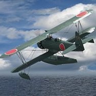
The Main Course is brailed up. The painting below shows several ships at Fighting Sail. You can see that the Courses have all been brailed up vs either clewed up or furled; which was a very very common configuration. Brailing up the Courses was done for three primary reasons. First, it reduced both damage to the Courses and the chance of fire - always a deadly threat to wooden ships. Second it reduced strain on the Fore and Main masts and the rigging generally. Courses were not really needed for close in maneuvering and not having them deployed also meant that not as many crew were required to work the sails during battle. Finally the command section and quartermasters steering did not have their forward view impeded while at their battlestation on the Quarterdeck. I tried to get my Main Course to look close to those in the painting.
The first step to brailing up a Course is to pull the clew lines until the corners are pulled up past the mid-line of the course. I chose to work one side of the main
course one line at a time as I am a crew of one <grin>. The shot below show how the course looks with the clew lines under light tension.
Close up of the clew blocks. These would have been touching, or nearly so, when the corners of the course were pulled up. As an aside, I am still researching
whether the sheet and tack lines would have been run through their respective blocks at the corners when a course was brailed up; and if they were not run
where were the lines placed.
Next the leech line was drawn until the edge of the course was pulled into a triangular like fold located at the top front outer part of the sail. The two photos
below show the end result. In the first shot you can make out the triangular section in the upper right part of the sail/yard.
The bunt lines were then worked to raise the center part of the course. Again, two photos, one fore the other aft, show the bunt lines under light tension as
the course is worked into shape.
The final aft and fore shots show the near final result. I only have to do some minor shaping of the folds and then brush on a final coat of whits glue thinned
50/50 with water to fix the shape of the course. As the course is fairly loosely bunched it could be quickly deployed if required.
I just need to place the Top Yard and sail back into position and the main mast will be ready to step.
Ernest
-
Greif8 got a reaction from MikeMaben in USS Constitution Tribute Build
Poor weather this weekend meant I could spend a lot of time at the bench and I managed to make a fair amount of progress. Bending the sails to the yards is some pretty exacting work as there is a fair amount of prep and while the technique of attaching the sails to the yards is not complex, you have to pay very close attention to where you are running a line as it is very easy to cross an area that should not be crossed! I had to re-thread several lines to get them right, but I got there in the end. My wife got a good laugh when she looked in on me yesterday while I was sewing loops into the corners of a sail. She said I looked like I was learning to be a seamstress!
Below is where things stand right now.
A shot of the front of the Main and Mizzen masts with the Royal, Topgallant and Top sails in place. The Main Top sail is a big beast.
And here is a look at the backside of those masts and sails. You can see I have stacked the clew and sheet lines for the Royal and Topgallant sails out of the way
so I could work without them being in the way.
Closeup of the Mizzen Top Sail bent to it's yard.
More prep work was required for the Main Course then the other sails as it, and the Fore Course, will be "Brailed Up" and needed to be prepared for that process.
Here is a close up of one of the loops at the lower corner. I have given it, and the other loop, extra seizing as that is how these were actually rigged.
Each corner has three blocks fastened to it. The smaller block will have a clew line run through it and the two larger blocks will have a sheet and tack line
run through them, one line for each block.
The Main Course bent to it's yard. This took some time as the yard has a lot of stuff attached to it and I really had to work slowly to make sure I ran all the
attachment lines right.
Photo showing the Mainmast with all four sails attached, though the Royal is not in the photo. The Top Sail and yard will be temporarily removed while I work
on prepping the Main Course to be "Brailed Up" and then actually doing that. Looks rather majestic in this shot I think.
The lines that will be used to "Brail Up" the Main Course have been attached and run. Here are the clew lines ready to be worked. The other six tan lines
belong to the leech and bunt lines.
Those lines run in front of the sail. The line attached near the outer mid-point of the sail is a leech line, and the two inner lines are bunt lines. These lines run
through blocks attached to the yard and then up to and through further blocks positioned under the fighting top before teminating at the respective spots on
the belays. They work together with each other and the clew lines to position the Course in a few different configurations.
Closer shot of the starboard lines.
This should give a good appreciation for just how complex - and crowded - the rigging on a square rigged ship of the time was. Getting all this run correctly
requires a lot of thinking ahead both to run the lines correctly, but just as importantly, thinking through the best sequence to do this so that you can maximize
the effectiveness of the process while minimizing either the chance of breaking something, or to have an unpleasent surprise later as you find out you can't reach
a spot to run a line. All that said, I am having a (mostly) good time doing this; it is pretty cool to see the rigging "grow" with each step, and I have enjoyed learning
how standing and running worked, and figuring out to replicate that - at least in part on this build.
The next update will show the Main Course "Brailed Up".
Ernest
-
 Greif8 got a reaction from LSP_Ray in USS Constitution Tribute Build
The Main Course is brailed up. The painting below shows several ships at Fighting Sail. You can see that the Courses have all been brailed up vs either clewed up or furled; which was a very very common configuration. Brailing up the Courses was done for three primary reasons. First, it reduced both damage to the Courses and the chance of fire - always a deadly threat to wooden ships. Second it reduced strain on the Fore and Main masts and the rigging generally. Courses were not really needed for close in maneuvering and not having them deployed also meant that not as many crew were required to work the sails during battle. Finally the command section and quartermasters steering did not have their forward view impeded while at their battlestation on the Quarterdeck. I tried to get my Main Course to look close to those in the painting.
The first step to brailing up a Course is to pull the clew lines until the corners are pulled up past the mid-line of the course. I chose to work one side of the main
course one line at a time as I am a crew of one <grin>. The shot below show how the course looks with the clew lines under light tension.
Close up of the clew blocks. These would have been touching, or nearly so, when the corners of the course were pulled up. As an aside, I am still researching
whether the sheet and tack lines would have been run through their respective blocks at the corners when a course was brailed up; and if they were not run
where were the lines placed.
Next the leech line was drawn until the edge of the course was pulled into a triangular like fold located at the top front outer part of the sail. The two photos
below show the end result. In the first shot you can make out the triangular section in the upper right part of the sail/yard.
The bunt lines were then worked to raise the center part of the course. Again, two photos, one fore the other aft, show the bunt lines under light tension as
the course is worked into shape.
The final aft and fore shots show the near final result. I only have to do some minor shaping of the folds and then brush on a final coat of whits glue thinned
50/50 with water to fix the shape of the course. As the course is fairly loosely bunched it could be quickly deployed if required.
I just need to place the Top Yard and sail back into position and the main mast will be ready to step.
Ernest
-
 Greif8 got a reaction from TankBuster in USS Constitution Tribute Build
The Main Course is brailed up. The painting below shows several ships at Fighting Sail. You can see that the Courses have all been brailed up vs either clewed up or furled; which was a very very common configuration. Brailing up the Courses was done for three primary reasons. First, it reduced both damage to the Courses and the chance of fire - always a deadly threat to wooden ships. Second it reduced strain on the Fore and Main masts and the rigging generally. Courses were not really needed for close in maneuvering and not having them deployed also meant that not as many crew were required to work the sails during battle. Finally the command section and quartermasters steering did not have their forward view impeded while at their battlestation on the Quarterdeck. I tried to get my Main Course to look close to those in the painting.
The first step to brailing up a Course is to pull the clew lines until the corners are pulled up past the mid-line of the course. I chose to work one side of the main
course one line at a time as I am a crew of one <grin>. The shot below show how the course looks with the clew lines under light tension.
Close up of the clew blocks. These would have been touching, or nearly so, when the corners of the course were pulled up. As an aside, I am still researching
whether the sheet and tack lines would have been run through their respective blocks at the corners when a course was brailed up; and if they were not run
where were the lines placed.
Next the leech line was drawn until the edge of the course was pulled into a triangular like fold located at the top front outer part of the sail. The two photos
below show the end result. In the first shot you can make out the triangular section in the upper right part of the sail/yard.
The bunt lines were then worked to raise the center part of the course. Again, two photos, one fore the other aft, show the bunt lines under light tension as
the course is worked into shape.
The final aft and fore shots show the near final result. I only have to do some minor shaping of the folds and then brush on a final coat of whits glue thinned
50/50 with water to fix the shape of the course. As the course is fairly loosely bunched it could be quickly deployed if required.
I just need to place the Top Yard and sail back into position and the main mast will be ready to step.
Ernest
-
 Greif8 got a reaction from LSP_Kevin in USS Constitution Tribute Build
The Main Course is brailed up. The painting below shows several ships at Fighting Sail. You can see that the Courses have all been brailed up vs either clewed up or furled; which was a very very common configuration. Brailing up the Courses was done for three primary reasons. First, it reduced both damage to the Courses and the chance of fire - always a deadly threat to wooden ships. Second it reduced strain on the Fore and Main masts and the rigging generally. Courses were not really needed for close in maneuvering and not having them deployed also meant that not as many crew were required to work the sails during battle. Finally the command section and quartermasters steering did not have their forward view impeded while at their battlestation on the Quarterdeck. I tried to get my Main Course to look close to those in the painting.
The first step to brailing up a Course is to pull the clew lines until the corners are pulled up past the mid-line of the course. I chose to work one side of the main
course one line at a time as I am a crew of one <grin>. The shot below show how the course looks with the clew lines under light tension.
Close up of the clew blocks. These would have been touching, or nearly so, when the corners of the course were pulled up. As an aside, I am still researching
whether the sheet and tack lines would have been run through their respective blocks at the corners when a course was brailed up; and if they were not run
where were the lines placed.
Next the leech line was drawn until the edge of the course was pulled into a triangular like fold located at the top front outer part of the sail. The two photos
below show the end result. In the first shot you can make out the triangular section in the upper right part of the sail/yard.
The bunt lines were then worked to raise the center part of the course. Again, two photos, one fore the other aft, show the bunt lines under light tension as
the course is worked into shape.
The final aft and fore shots show the near final result. I only have to do some minor shaping of the folds and then brush on a final coat of whits glue thinned
50/50 with water to fix the shape of the course. As the course is fairly loosely bunched it could be quickly deployed if required.
I just need to place the Top Yard and sail back into position and the main mast will be ready to step.
Ernest
-
Greif8 reacted to red Dog in Going to the deep side : U-552 DKM 1/48
And resupply U-boats, providing fuel, munitions and food supply to the other attack boats. The story is quite interesting.
I stalled a bit on the forward torpedo room because of the empty foreground.
Trumpeter wants you to simply place two air tanks there but that leaves a lot of empty spaces and play against the cramped area I want to try to depict with this build.
These tanks are not correctly located and are partly under the bunks. But if I build bunks on top of them they will be too high so I decided to cut the floor,
create a 3D piece to mirror the opposite side and display the lower bunks.
The tanks are relocated and attached from above. If I add a floor for them I'll hide too much of the torpedo storage room under the floor of the room.
That's not perfect but the best compromise I could come up with.
I intend to show a lot of supplies throughout the boat and try to render the mess it must have been in there with 40-50 stinking males confined in there.
I went to cult-3D and downloaded as much stuff as possible and scaled them to 48th scale. Plates, coffeepots, cooking pots, rice bags, potatoes bags, tin cans, fruit cases, salads, carrots, 88mm shells & cardboard casings, etc . All these will compliment nicely what I could gather from black dog supplies.
I just haven't found ham and sausages yet but I want them to hang from the floor and I am thinking about hanging hammocks full of supplies from the roof of the torpedo room.
Here's very early impression of what I am leaning to:
I am also debating to put 2 more torpedoes on the floor as it was often done, must made the crew life really difficult
-
Greif8 reacted to red Dog in Going to the deep side : U-552 DKM 1/48
No idea short of guessing someone made a terrible mistake confusing left and right
That said, that acrylic side is not great for a look through. It's quite thick and you get a lot of diffraction.
I plan on solving the issue by cutting it. So I'll cut the acrylic side on the hull and cut the plain side on the conning tower.
and paint the rest.
Initially I wanted to have this beast surfaced but in a transparent resin box to simulate the ocean.
This seems to be overkill and present too many challenges (experience with large volume of deep ocean water resin, costs and a high risk of not seeing anything inside after all.
I would love to have a resin box that I could add or remove the sub from. But that's something I can hopefully give some thoughts at the last stage of this project.
-
Greif8 reacted to red Dog in Going to the deep side : U-552 DKM 1/48
Wood grain is something new for me.
So new that I actually forgot how I painted the first pieces and I had to search again when I wanted to paint the next run of walls
Yet it is quite simple...
So I'm documenting this in case my old brain has a blank again
First a base coat of XF-57
then brush paint oil Burnt sienna and leave for 10-15 minutes
then remove paint with a flat brush following the wood vein direction. remove paint from the brush, do it again
Play with the effect until desired result but always dry clean the brush before the next pass.
Then leave to cure for a week. When impatient, wait a day or two, then airbrush a thin coat of varnish so at least you can take them with your fingers. But it will remain delicate until fully cured and that may take a week.
-
Greif8 reacted to red Dog in Going to the deep side : U-552 DKM 1/48
Thanks guys.
Definitely watched das boot, but nowadays I am a big fan of Greyhound
Work started a few weeks ago on the forward torpedo compartment.
Here are blueprints in side and top view:
It is made of different section:
- the bulkhead
- the floor
- the 4 fishes stored under the floor (I should remove the det)
- the 4 launcher tubes
- the side wall with the 6 bunks.
Interesting things might happen in this compartment.
- It can be packed with sleeping crew, in the bunks and on the floor.
- The crew can be set loading one of the torpedo tube (which is the option I probably will chose as it goes better with the rest of the scenario I'll show)
- Torpedoes can be loaded from above deck, and slide into the compartment through the pressure hull. One might think that the boat needs to be docked for that but there is one fish stowed in its own pressure tube, just under the deck floor that the crew could get while at sea.
It's a complicated manoeuvre they did on the surface being very vulnerable in calm seas, using the cradle and a winch on top of a pole, placed between the loading hatch and the tower. The same winch was used to pull the fish out of it's rotated stowage tube and to let it slide into the forward (or aft -as the same mechanism was available aft) torpedo room.
I'm not ruling out the option, but at this time I am considering 88mm gun in action so that rules out torpedo loading above deck.
Current compartment painting is made with acrylics:
XF-66 for dark grey, H338 for light grey.
The fishes are aluminium XF-16 and their head bronze X-33; props and fuses are painted gold X-31. The floor is X-32
Wood is made with oils which I'll detail in the next post.
Weathering the floor has started but it's far from being finished
The launching tubes parts are not quite detailed. RC Subs provide the tube doors and I will detail these later on. The forward pressure hull part is provided in resin by RC Subs as well. If you don't have it the pressure hull is flat and that's highly visible. So this part is quite necessary IMHO. I will probably detail the visible side of the tubes a bit more later on.
Then comes the back wall with the frames for the bunks.
Trumpeter obviously couldn't detail the right side of the room since doing so would prevent us to look inside, but they could have done a bit better nevertheless.
I intent to add at least a few lower bunks which should not impact the view inside and leave enough space to look at the rest of the room.
Then I stalled on how to implement the bunks.
Trumpeter only offer a plastic part for the mattresses which really aren't up to par. I initially cut some thin slice of foam which I intended to paint white but I wasn't satisfied with the result. It took me a while to figure it out.
I designed mattresses and pillows and 3D printed them (a bunch of them)
then designed a decal for the linen (white was too immaculate and I wanted something more military issued) and laser printed them on a blank white decal sheet
And finally I created the blankets with toilet paper soaked with a mixture of PVA glue and water.
Result after the basic layer of paint::
Much better although the linen need another coat of decal solution.
Normally the bunks are folded up when loading torpedoes, a process I intend to show. But I'll load one of the right side tube to keep clear from the beds and populate the open side of the room. Lots of details will also required on the back walls
The roof has been painted in light grey with the wood framing. The loaded torpedo will hang from there and I intend to add a lot of supplies in the room as well.
4-5 leds will be wired on the roof for compartment lighting as this turns pretty dark once the roof is closed.
i'll try to manage the electrical side of things at later stage of the built. But I need to plan a bit ahead to make sure I still can add lights where I need them without destroying too much of the prior work.
-
 Greif8 got a reaction from Shoggz in USS Constitution Tribute Build
The Main Course is brailed up. The painting below shows several ships at Fighting Sail. You can see that the Courses have all been brailed up vs either clewed up or furled; which was a very very common configuration. Brailing up the Courses was done for three primary reasons. First, it reduced both damage to the Courses and the chance of fire - always a deadly threat to wooden ships. Second it reduced strain on the Fore and Main masts and the rigging generally. Courses were not really needed for close in maneuvering and not having them deployed also meant that not as many crew were required to work the sails during battle. Finally the command section and quartermasters steering did not have their forward view impeded while at their battlestation on the Quarterdeck. I tried to get my Main Course to look close to those in the painting.
The first step to brailing up a Course is to pull the clew lines until the corners are pulled up past the mid-line of the course. I chose to work one side of the main
course one line at a time as I am a crew of one <grin>. The shot below show how the course looks with the clew lines under light tension.
Close up of the clew blocks. These would have been touching, or nearly so, when the corners of the course were pulled up. As an aside, I am still researching
whether the sheet and tack lines would have been run through their respective blocks at the corners when a course was brailed up; and if they were not run
where were the lines placed.
Next the leech line was drawn until the edge of the course was pulled into a triangular like fold located at the top front outer part of the sail. The two photos
below show the end result. In the first shot you can make out the triangular section in the upper right part of the sail/yard.
The bunt lines were then worked to raise the center part of the course. Again, two photos, one fore the other aft, show the bunt lines under light tension as
the course is worked into shape.
The final aft and fore shots show the near final result. I only have to do some minor shaping of the folds and then brush on a final coat of whits glue thinned
50/50 with water to fix the shape of the course. As the course is fairly loosely bunched it could be quickly deployed if required.
I just need to place the Top Yard and sail back into position and the main mast will be ready to step.
Ernest
-
 Greif8 got a reaction from LSP_K2 in Most completions in a single year?
2020 for me; I completed 5 LSP builds and 3 builds of other topics.
Ernest
-
 Greif8 got a reaction from denders in USS Constitution Tribute Build
The Main Course is brailed up. The painting below shows several ships at Fighting Sail. You can see that the Courses have all been brailed up vs either clewed up or furled; which was a very very common configuration. Brailing up the Courses was done for three primary reasons. First, it reduced both damage to the Courses and the chance of fire - always a deadly threat to wooden ships. Second it reduced strain on the Fore and Main masts and the rigging generally. Courses were not really needed for close in maneuvering and not having them deployed also meant that not as many crew were required to work the sails during battle. Finally the command section and quartermasters steering did not have their forward view impeded while at their battlestation on the Quarterdeck. I tried to get my Main Course to look close to those in the painting.
The first step to brailing up a Course is to pull the clew lines until the corners are pulled up past the mid-line of the course. I chose to work one side of the main
course one line at a time as I am a crew of one <grin>. The shot below show how the course looks with the clew lines under light tension.
Close up of the clew blocks. These would have been touching, or nearly so, when the corners of the course were pulled up. As an aside, I am still researching
whether the sheet and tack lines would have been run through their respective blocks at the corners when a course was brailed up; and if they were not run
where were the lines placed.
Next the leech line was drawn until the edge of the course was pulled into a triangular like fold located at the top front outer part of the sail. The two photos
below show the end result. In the first shot you can make out the triangular section in the upper right part of the sail/yard.
The bunt lines were then worked to raise the center part of the course. Again, two photos, one fore the other aft, show the bunt lines under light tension as
the course is worked into shape.
The final aft and fore shots show the near final result. I only have to do some minor shaping of the folds and then brush on a final coat of whits glue thinned
50/50 with water to fix the shape of the course. As the course is fairly loosely bunched it could be quickly deployed if required.
I just need to place the Top Yard and sail back into position and the main mast will be ready to step.
Ernest
-

-
-
 Greif8 got a reaction from Archimedes in Most completions in a single year?
2020 for me; I completed 5 LSP builds and 3 builds of other topics.
Ernest
-
Greif8 reacted to Thunnus in Tamiya 1/32 Spitfire XIVe Conversion (Laminar Flow Design)
Hello LSP community! It's been a while since I've spent meaningful time at my modeling bench but I'm getting that urge again. Not sure what project I want to continue on at the moment but as I'm contemplating, I thought I'd crack open the Spitfire build again and try to re-orient myself. I left off exploring the 3D-printed cockpit upgrades from Laminar Flow Designs. I'm trying to mix the Tamiya XVIe cockpit parts with the LFD XIVe-specific upgrades and adding Barracuda resin on top of that, where applicable. As usual, I am not going to claim great accuracy with what I'm doing but will use the resources that I have available to make a reasonable facsimile of an XIVe cockpit. One of these resources has been previous Spitfire builds, most notably NGBZ's VIII build from 2020. From what I know, the XIVe cockpit is based on the VIII and Gary's build does a great job of capturing some of those differences with some help of Vincent K's past scratchbuilding work. Of course, there are differences between the XIVe and VIII so I have to pay attention to that too.
I started modifying the Tamiya kit parts to accommodate the LFD upgrades. The biggest change is the big electrical box that needs to be added to the port sidewall. Some surgery is needed on the kit part to make room for the electrical box.
After making most of the necessary modifications like moving the voltage regulator, making a jackplate for the gun camera film footage indicator out of sheet styrene and filling in ejector pin marks, I've tacked the rest of the port sidewall components into place just to get a feel for the wiring that I'll be adding later.
There is a big fuel tank directly behind the seat, which will block the view off from the seat bulkhead to the rear. This will limit visibility into the rear bottom area of the cockpit so I'm not going to bother with trying to replicate the flying control linkage wires that run under the pilot, which I was previously considering.
I've done similar modifications to the starboard side, which features a resin sidewall replacement from Barracuda.
My plan is to separate the cockpit into subassemblies... the port and starboard sides as presented above, the instrument panel/cockpit floor and the seat/rear bulkhead. Once these subassemblies are assembled and painted separately, I'll put them together as the fuselage halves come together.
-
Greif8 reacted to Thunnus in Tamiya 1/32 Spitfire XIVe Conversion (Laminar Flow Design)
It's been a while but I think I can get back onto this build. After starting this build, I've learned that the XIVe cockpit differs in some ways from the XVIe and I wanted to attempt to address some of those differences. The most significant is a big control panel that resides on the port sidewall.
A rectangular box can be a relatively simple thing to scratchbuild but I personally have trouble getting square corners on boxes. When I saw that Mathieu at Laminar Flow Design was developing a set of XIV-specific cockpit details including the control panel, I decided to wait for it to save me some work. It took a while but I finally got it...
Like his other 3D-printed products, Mathieu incorporates a protective crate around the printed parts. He graciously include an entire spare set and I found that the spare set was definitely needed.
Here are the parts still attached to the base but with the protective walls removed. Many of these parts are super tiny and lots of patience and care needs to be taken when removing the parts for use.
I tried to be careful but I still managed to lose and/or break a few parts. Mathieu includes two copies of the especially small or fragile parts in each set so sometimes I had four copies to work with. I needed all four removal attempts to get a complete throttle lever detached without breaking!
After the parts were freed completely from their printed supports, I glued together the sub-assemblies. These included the pilot door and crowbar, throttle quadrant, landing gear control quadrant, cylinder priming pump. The control panel, waffle-style foot guards, canopy crank and a small trim wheel are stand alone items.
The parts were given a light coat of primer (Mr Primer Surfacer 1000).
I've got a lot of Spitfire cockpit stuff from Barracuda as well so I'll to sort out which bits I'll be using. One of these is a resin seat with the backrest cushion, which looks to be a nice upgrade from the kit parts.
-
Greif8 reacted to Thunnus in Tamiya 1/32 Spitfire XIVe Conversion (Laminar Flow Design)
In a bit of a holding pattern as I await some XIVe specific cockpit parts from Laminar Flow Designs. Decided to kill some time and assemble and paint the kit instrument panel to see how it would compare with the Quinta Panel. I started off trying to use the decals for the gauges but I had Airscale's instrument decals as well as the PE instrument bezel fret so it was dressed up with those. And I topped each gauge with a clear acetate disc.
Obviously a lot less detail than the Quinta panel but I do like the less cluttered look of the kit panel and the superior contrast between the individual elements.
-
Greif8 reacted to Thunnus in Tamiya 1/32 Spitfire XIVe Conversion (Laminar Flow Design)
Thank you Matt! Spraying the resin parts with some primer helps to see the detail.
Thank you! I got my conversion set from the first production run offered by LFD back in August. Mathieu states that the next offering date for the XIVe conversion will be sometime in December. To ensure you get a copy, I recommend following his page on Facebook as he is posts regular updates there and will give a heads up when the website will reflect new stock.
With the daughters visiting, I haven't had much time on the modeling bench. I took a few hours looking at some of the cockpit parts. These bulkheads have lightening holes molded as circular depressions.
The holes were drilled out.
Three versions of the control stick. On the left is the kit part. In the middle is the resin version from Barracuda's Spitfire Cockpit Upgrade set. The wires were added after assembly. On the right is the more recent digitally printed control stick from Barracuda.
-
Greif8 reacted to Thunnus in Tamiya 1/32 Spitfire XIVe Conversion (Laminar Flow Design)
I decided to mount the Quinta instrument panel so the raised details on the kit part needs to be shaved down.
The backing on the Quinta panels is a little sticky after removing it from the decal sheet but not tacky enough to serve as a permanent attachment. So I used PVA glue.
I have a few choices for the Mark IID Gyro gun sight. The Tamiya part is on the right. The Barracuda resin sight in the middle. On the left is a spare resin gun sight from the Special Hobby Tempest kit. The Tamiya version is decent but the additional detail on the resin parts is very evident.
Checking to see how the Barracuda resin gun sight attaches to the instrument panel. The reflector glass and shroud still need to be added to the gunsight.
-
Greif8 reacted to Thunnus in Tamiya 1/32 Spitfire XIVe Conversion (Laminar Flow Design)
Fuselage modifications are not quite finished. I noticed that the paneling on the tail underneath the horizontal stabilizers were different between the XVIe and XIVe.
XVIe per Tamiya instructions...
XIVe per Junpei Temma's drawings...
So the errant panel lines and rivets were filled in with black CA glue.
New panel lines and hatches were scribed.
Checking our work with a primer coat.
-
Greif8 reacted to Thunnus in Tamiya 1/32 Spitfire XIVe Conversion (Laminar Flow Design)
The port side hatch removal is complete after a primer coat.
Here is a look at the Quinta instrument panel. I masked each dial with tape and shot the panel with some clear flat. All of the pre-painted stuff, whether it is Eduard photoetch or 3D decals, looks better with a flat coat.
-
Greif8 reacted to Thunnus in Tamiya 1/32 Spitfire XIVe Conversion (Laminar Flow Design)
After a brief hiatus, I am trying to ease my way back into the modeling workshop. Mathieu at Laminar Flow Design graciously sent me a set of fishtail exhausts based on my subject aircraft. His XIVe low-back conversion set includes only the round exhausts and was surprised to see the photo of EB-V with the fishtails clearly visible.
More modifications to the XVIe fuselage... the port hatch behind behind the cockpit needs to be removed. Interestingly, Claes Sundin's profile of EB-V shows this hatch in place but I think it is in error.
No hatch that I can see in the the photo.
There is a bit of raised detail around the hatch that needs to be removed before filling including the hinge on the top and fasteners on the bottom.
The hatch and rivets are filled in with black CA glue. I'll clean this up and shoot with a coat of primer when it is finished.
Next, I'm going to open the retractable tail wheel bay. LFD conveniently provides scribing/cutting templates. I am choosing to trace the cut lines in pencil and remove the template prior to cutting.
Dry-fitting the tail components. The horizontal stabilizers need to be adjusted for the extra width of the XIVe tail so surgery here is not quite finished.
EB-V was fighter version so the camera ports will not be used in this build. But I need to add a hatch on the starboard side. LFD provides the hatch as a separate part but I thought it'd be neater/easier to just scribe the hatch instead of cutting an opening and gluing the resin hatch into place. Again, LFD provides the hatch template, which is positively located using the interior fuselage ribs... no guessing. The template is secured into place with tape.
Using a sewing needle chucked into a pin vise, the hatch is scribed.
The rivets are filled in with black CA glue and new rivets and fasteners are applied.
A shot of primer to check our work.
I think most of the fuselage modifications are done so I can start looking at the cockpit next. I've picked up the Quinta 3D decal set for this build.
But the kit instrument panel has some nice 3D relief, which gives me a moment of pause. Although the 3D decals have some raised details, the molded details here are better. I'm going to look at the kit IP a little more closely before committing to the Quinta set.
-
Greif8 reacted to Thunnus in Tamiya 1/32 Spitfire XIVe Conversion (Laminar Flow Design)
Another observation... looking at the photo of the subject aircraft EB-v, notice the exhausts...
They are not the round exhausts that come with the LFD conversion set...
LFD did provide the highback conversion with both round and fishtail type exhausts...
So... a quick email was sent to Mathieu at LFD and was promptly promised a set of fishtail exhausts for my project. Thank you Mathieu for the quick customer service response!
-
Greif8 reacted to Thunnus in Tamiya 1/32 Spitfire XIVe Conversion (Laminar Flow Design)
I'm still not clear on this. MR32-020 are late style barrels for the E-wing. Same shape as the late barrels that I have (MR32-082) except different length.
Are you saying that MR32-082 are ok shape-wise as early barrels but need to be longer? I'll also check the Tamiya kit to see what barrels are included there.
Thank you! I chose to try the Quinta Studios cockpit set for this build...
Good to know!