

chuck540z3
-
Posts
2,540 -
Joined
-
Days Won
73
Content Type
Profiles
Forums
Events
Posts posted by chuck540z3
-
-
-
4 hours ago, chaos07 said:
Great work on the lights Chuck. The drill bit in the strobe is genius. I'll definitely be using some of your techniques in the future.
As a side note, I spent too much time altering the fit of the Kopecky LAU-129s to fit perfectly flush with the two underwing pylons, only to find a gap present on the leading and trailing edges bracketing the step that fits the launch rail. Not sure if you plan to have those on your build, but I'll have some re-work to do for mine.
Thanks Duane. I really appreciate your "heads Up" tips as we build this very cool kit at the same time- in very different directions!
As far as the Kopecky LAU-129 launchers are concerned under the wing, I don't seem to have any real gaps with the pylons, probably because I cut the notch based upon what the pylon required rather than what the Kopecky resin indicated. They fit really well right now and under the wing behind the wingtip launchers, any gap from the side cannot be seen.
No real update, other than I have applied a nice thin coat of Mr. Surfacer 1200 on everything to check for flaws (a few big ones) and mostly to get rid of that snow white plastic! Maybe I can photograph this build properly from now on with some level of color and contrast balance.
Cheers,
Chuck
- chaos07, Paul in Napier, scvrobeson and 1 other
-
 4
4
-
7 and proud of it! All I really knew is that the leader was Guy Gibson.

Cheers,
Chuck
- thierry laurent, Pete Roberts and Christa
-
2
-
 1
1
-
Thanks Niels and Guy!
Niels, The Modern Viper Guide book that I have shows this light on page 21, not 107, which is GBU-24 bombs instead, so maybe there are two editions? The caption on that page says that the position lights have "recently been modified to be compatible with NVG (Night Vision Goggles)", so I'm guessing that some Vipers just have a round light instead?
In any case, the light on page 21 isn't just the light blanked off at the front. The red lens is offset to the back of the housing so that 80% of the red color is still visible, with the rest blanked off like Guy's pic with dark grey. This blanked off area has the tiny InfraRed light at the front. Having said all that, the best solution that I see is to add a small half-moon dark decal to this area after painting, to get the "look" without worrying too much about how much of the lens still shows since it's in the middle. Same thing for the other InfraRed lights like the ones at the rear of the vertical stabilizer. A small cockpit decal that shows 4 tiny dots within the oval housing should do the trick. The 2 small IR lights at the rear of the intake navigation lights are already there in the plastic, so I'll just darken them with a wash.
I'd love to just take a pic of the book and post it here, but that would be crossing a big copyright line with our friend Jake.
Cheers,
Chuck
-
22 hours ago, Zola25 said:
Yes they should be deleted on both sides.
Those position light always gives me problems on the Tamiya kit as they seem to be both too large in diameter and also too thick to fit in the recess. They should be flush with the fuselage. I look forward to hear your experience and solution.
Niels
April 11/24
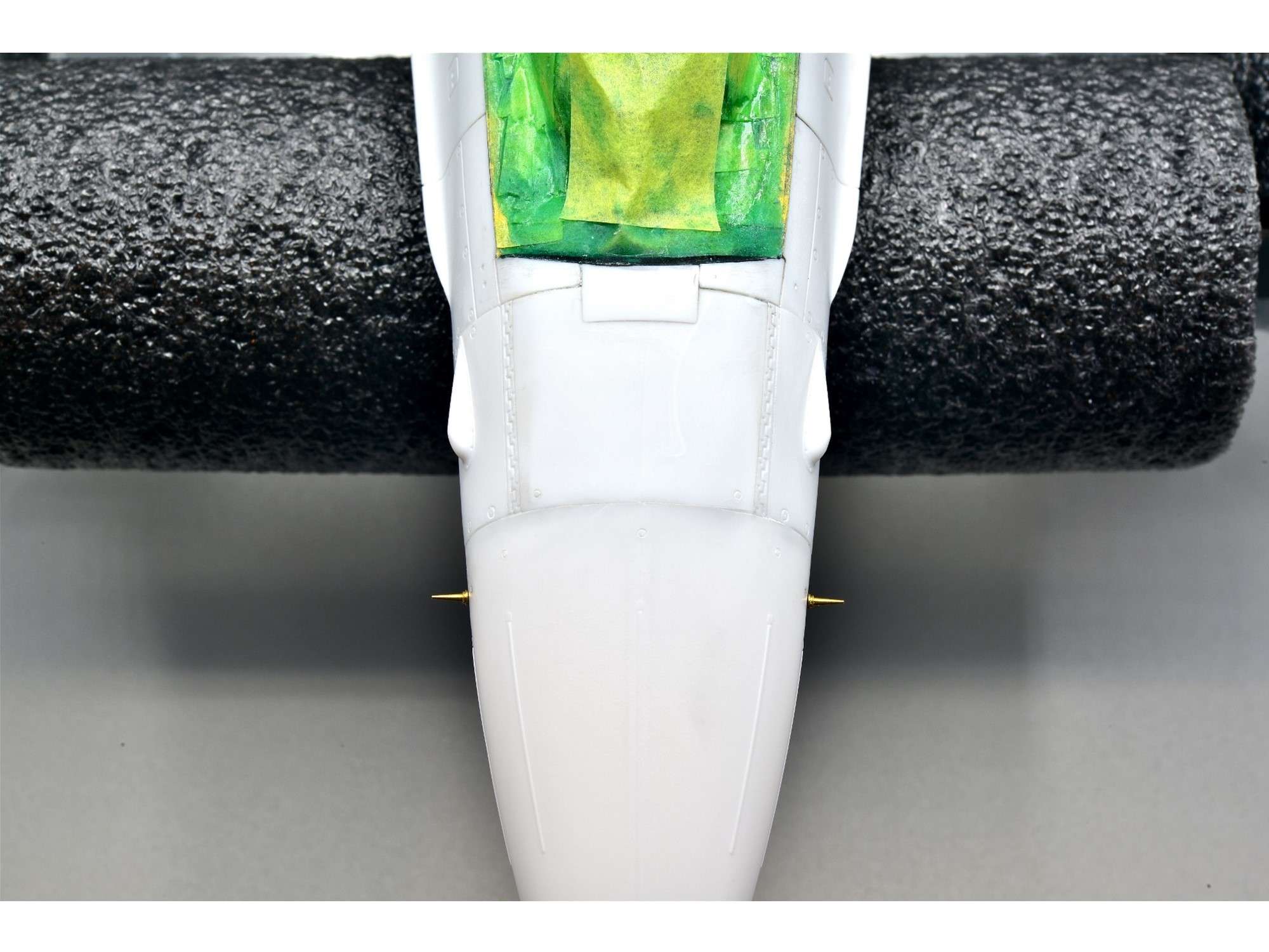
Here is the problem that Niels has pointed out. Also, after looking at many pics I have of F-16’s, I couldn’t find one with these panels on any of them either.
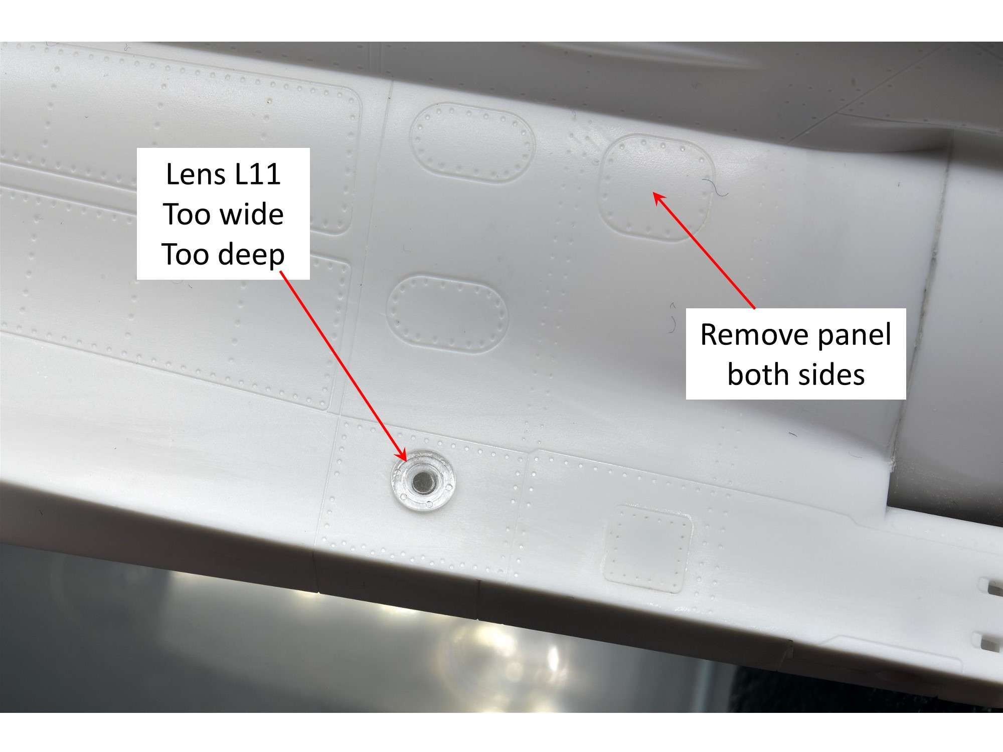
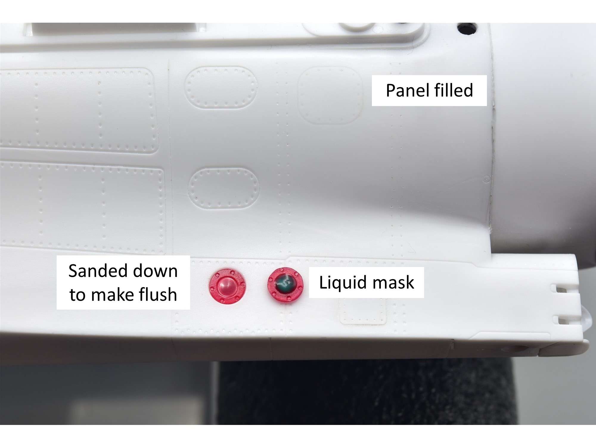
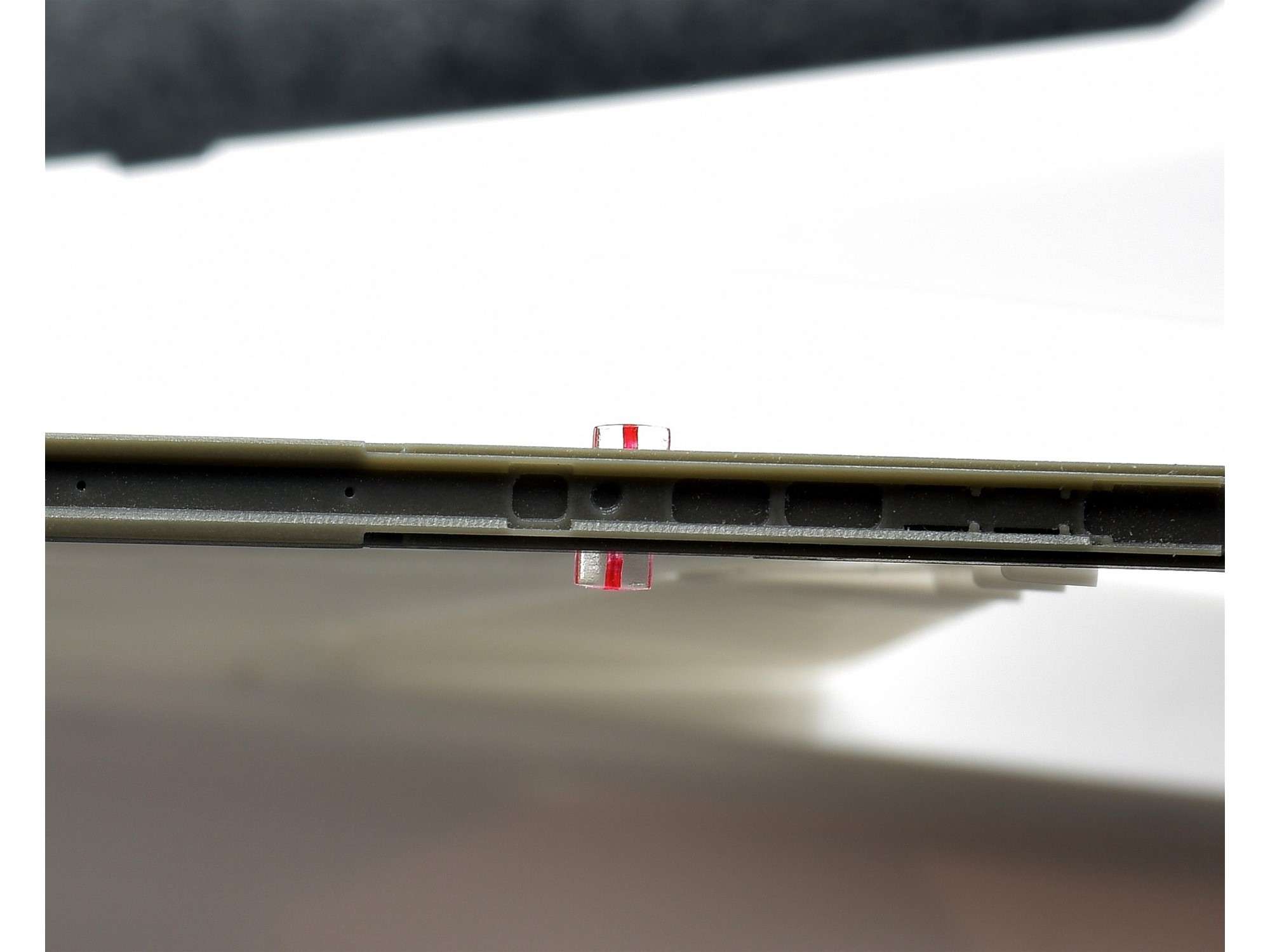
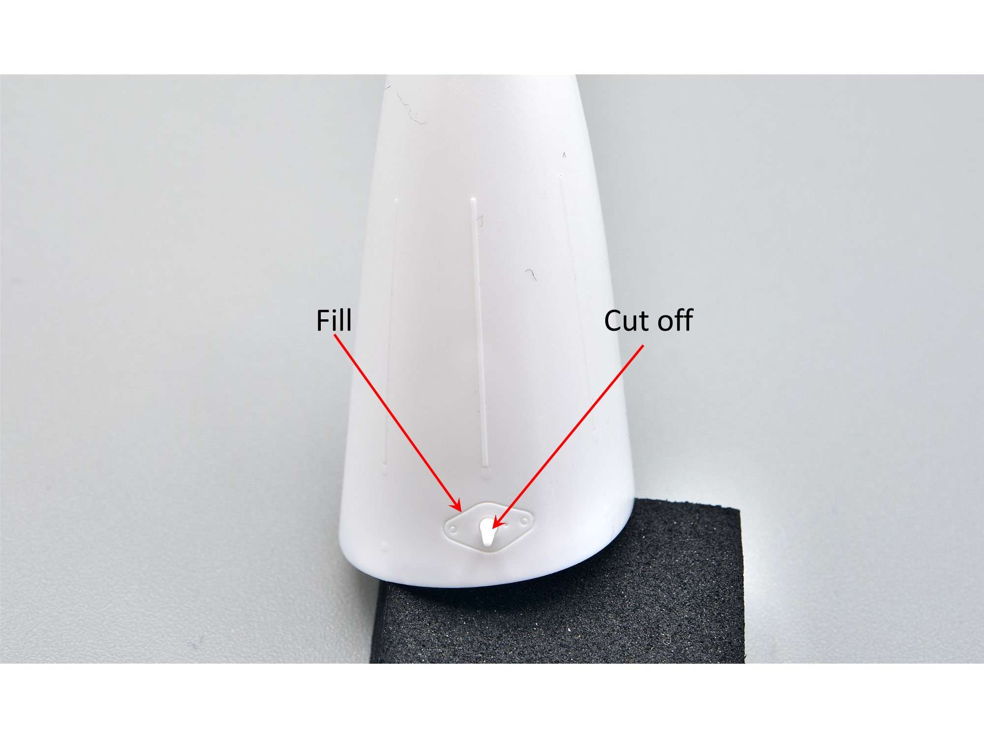
Although the lens is a bit too deep, the real fit culprit is the diameter, so I carefully sanded down the outside edge to get it to fit into the hole without removing the fastener detail, but also the depth quite a bit. These are position lights that are clearly red in Jake’s book (P 21), but the red color is almost at the surface. By making the lens thin and painting it red from behind, the red is shallow like it should be. There is also a tiny InfraRed Emitter light at the front of the light (left), which I will likely add later as a decal. Once the lights are cemented in and painted, you will only see red from the area covered with liquid mask on the right.
Since I was on to lights, I decided to attack the little navigation lights on the wingtips as well, which are part of the launchers with rods holding them in place. As Pete mentioned earlier, the lenses are not tinted red and blue/green like those on the intake, but have a small bulb in each with those colors instead. To accomplish this, I usually just drill a small hole from behind, then place a dab of the corresponding paint color in the hole as a bulb replacement. Unfortunately with these lights that are almost directly on top of each other, a hole from the bottom interferes with the other light, so as a compromise I just drilled holes from above, filled them with paint, then sealed them with clear CA glue. Not very accurate if you want the bulb look, but a lot better than a painted lens.
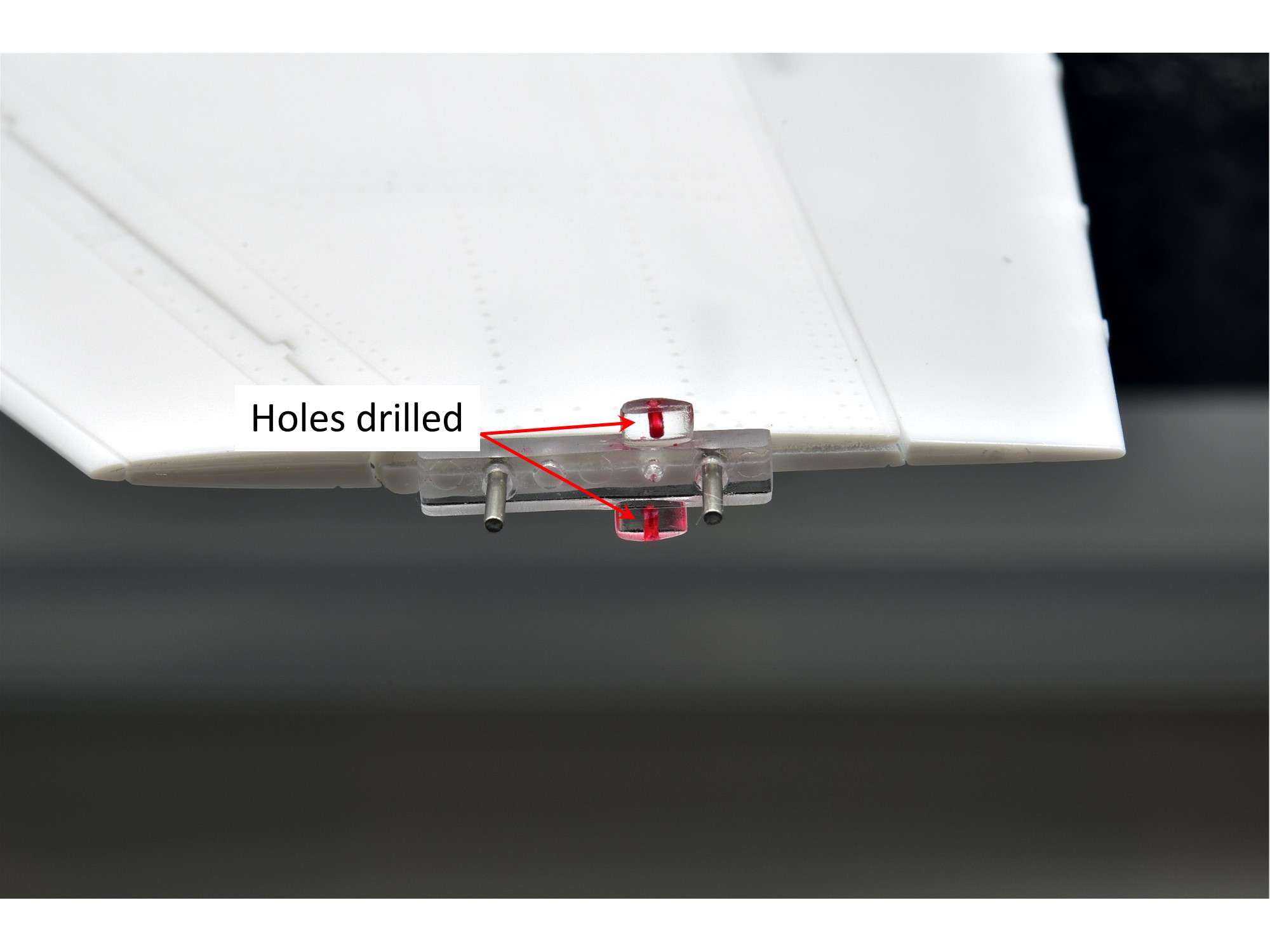
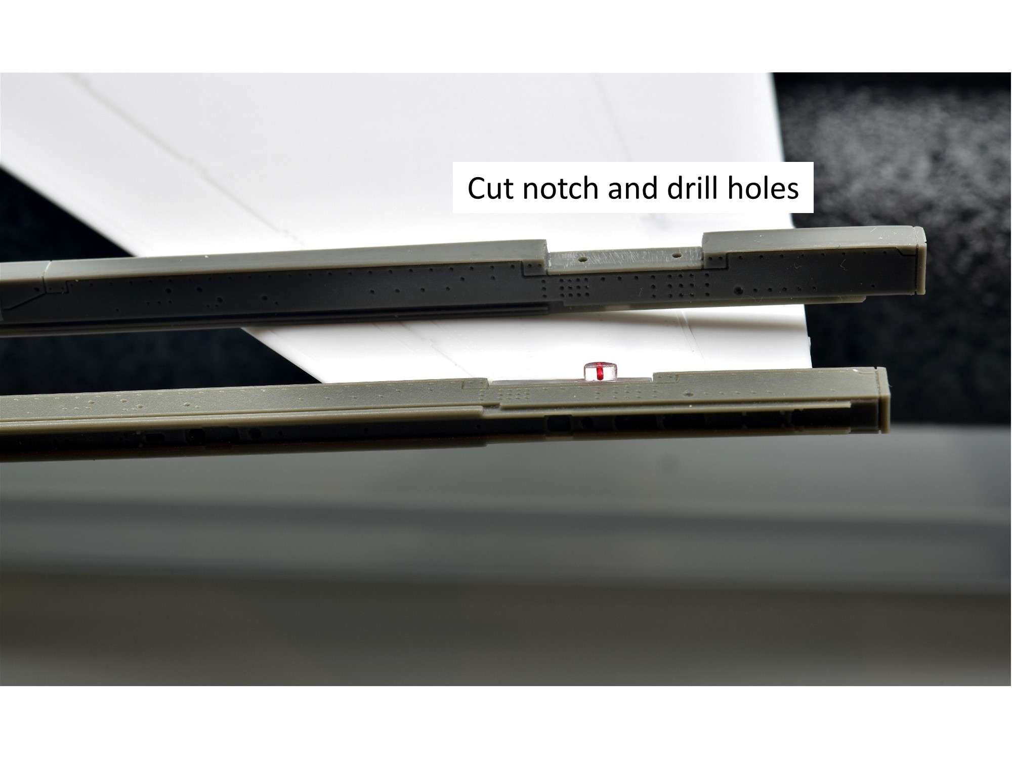
The Kopecky LAU-129 launchers need a notch cut out and holes drilled to fit the wingtip, so I used the kit parts as a guide for exact width and pin location.
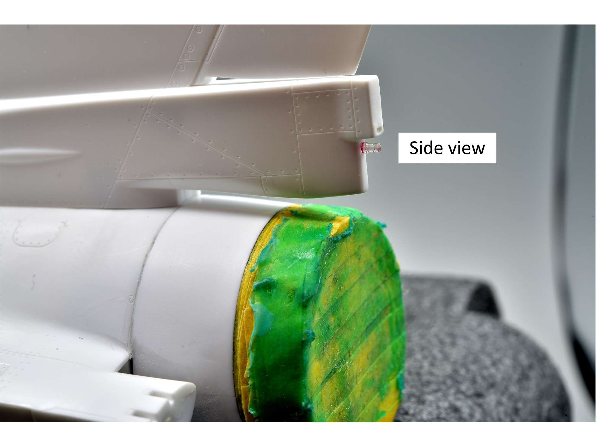
A view from the side, showing that the top light is always a bit offset to the rear. Not exactly the true bulb look, but this still looks better than painted lenses.
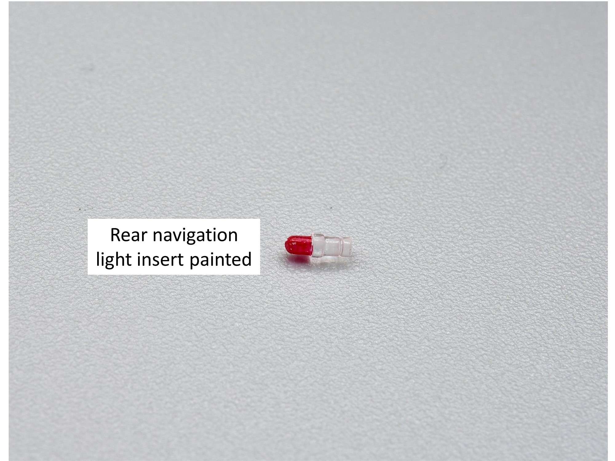
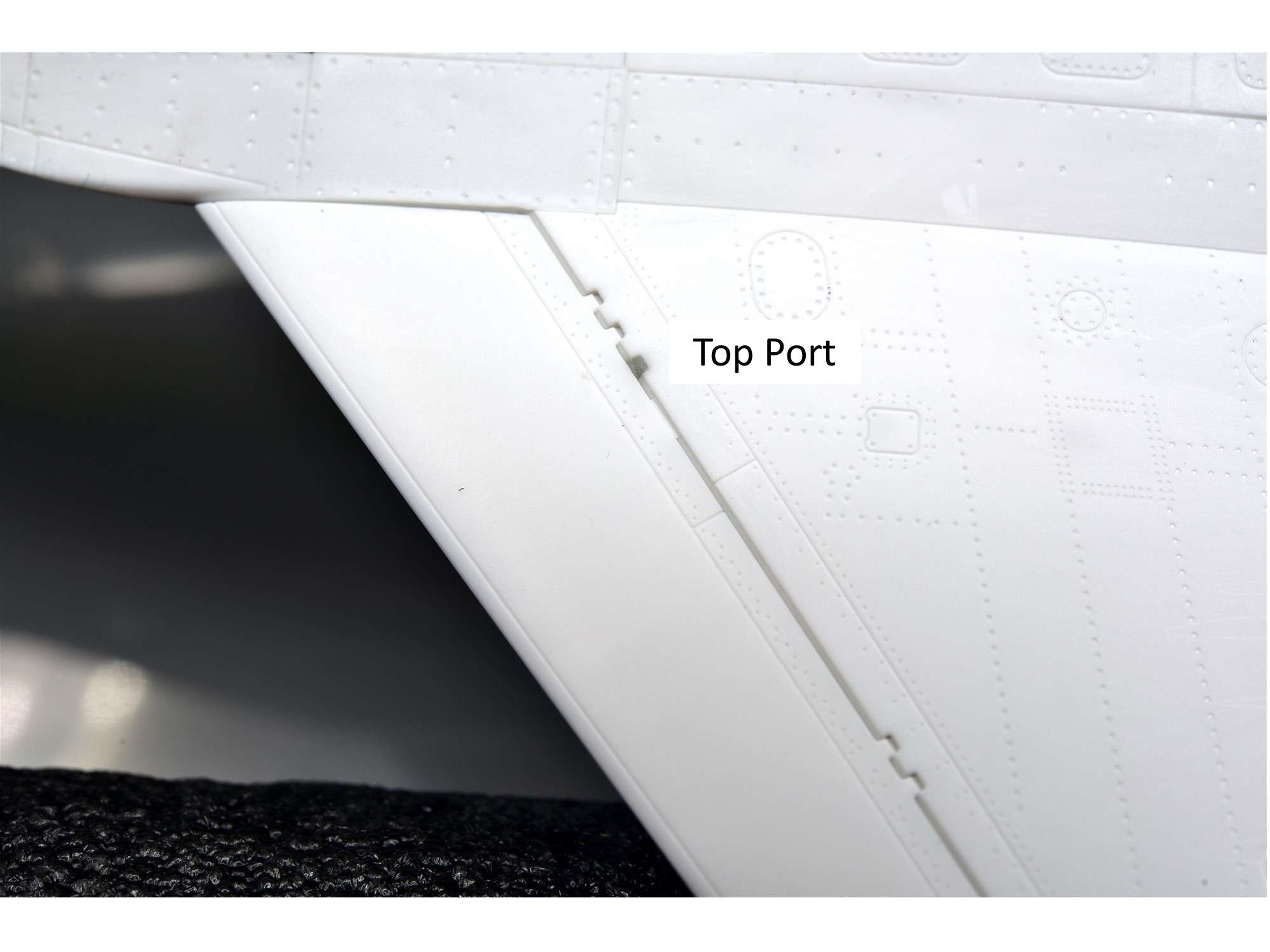
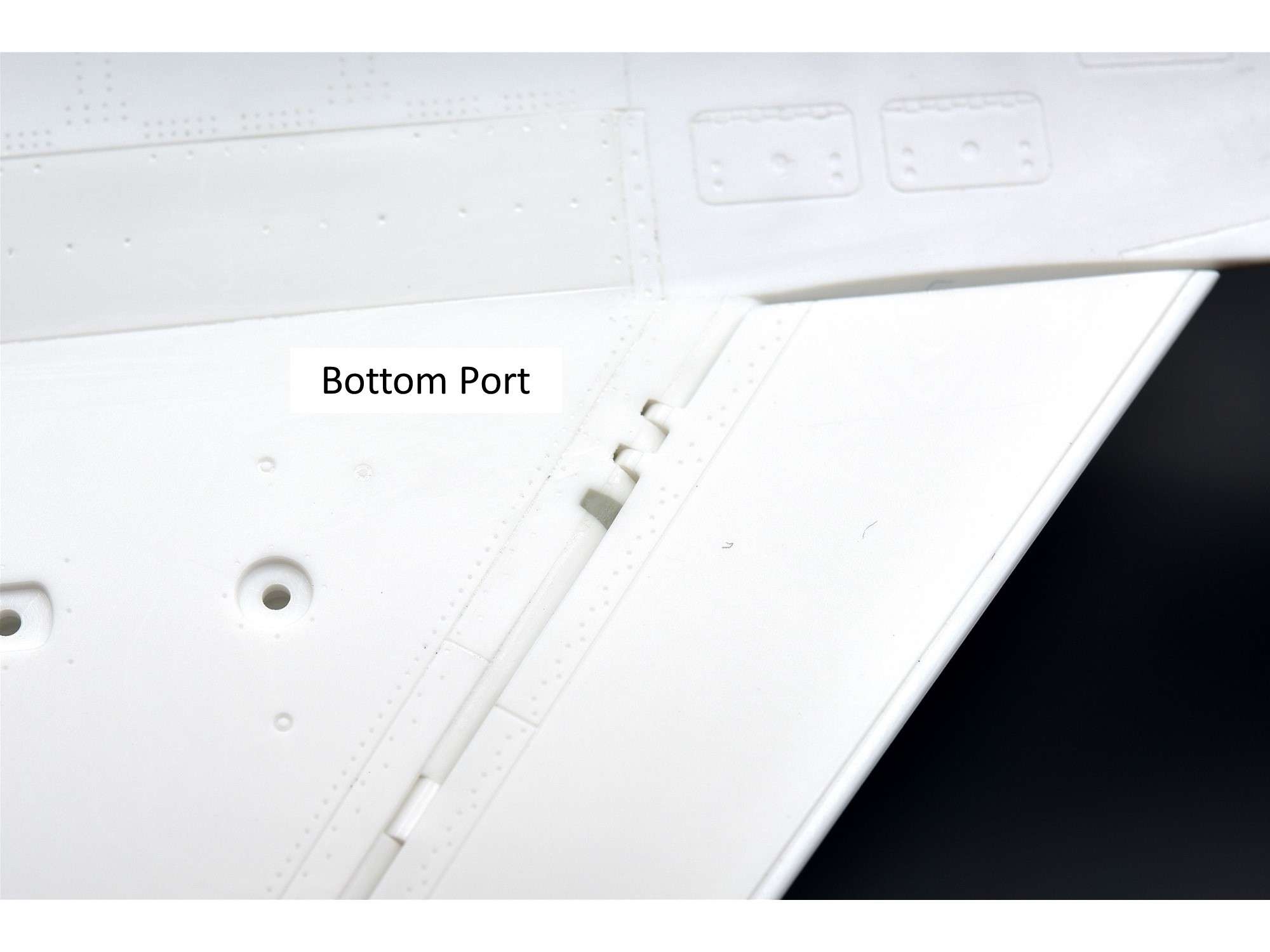
More lights and more detailing options. The rear navigation light is red, but only at the very back with the side’s painted fuselage color. Here I painted just the insert that goes into the tail, which is slightly scratched from repeated insertion. I'll fix that later....
From the side, you won’t see any red when the tail is painted.
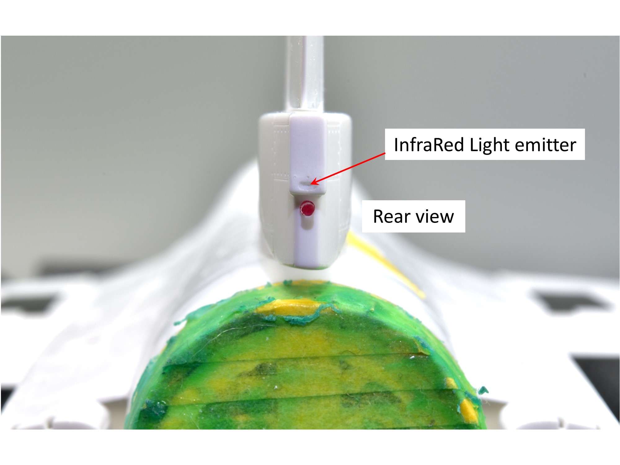
But from the rear, like a fiber optic, you can clearly see red. Above that light is an oval recess for 4 more tiny InfraRed light emitters where Tamiya placed an outward oval instead, that many modelers just cut off. Here I dug a small recess and added outside fastener detail, where I will again add a small decal inside later to replicate the lights.
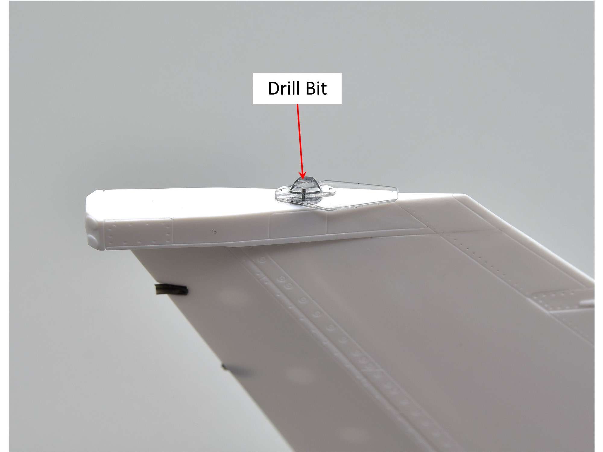
The anti-collision strobe light for the top of the tail has a silver light housing for a white light bulb. After drilling a hole from behind to replicate this a bit, I just left a used drill bit in the hole and glued it in after trimming it for size. I then painted the insert silver so that you can see some of that from above, much like the rear navigation light.
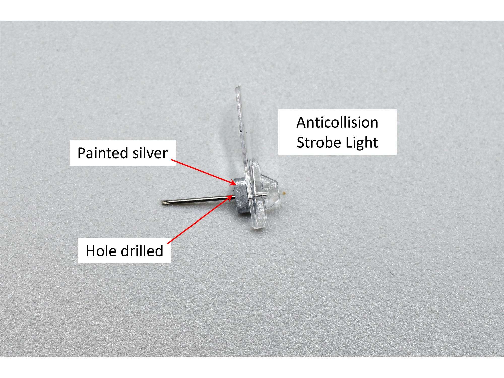
I had to be very careful about how deep I drilled the hole, because the lens at the top is tapered and very thin at the top. This about is about all I could do without risking ruining the part.
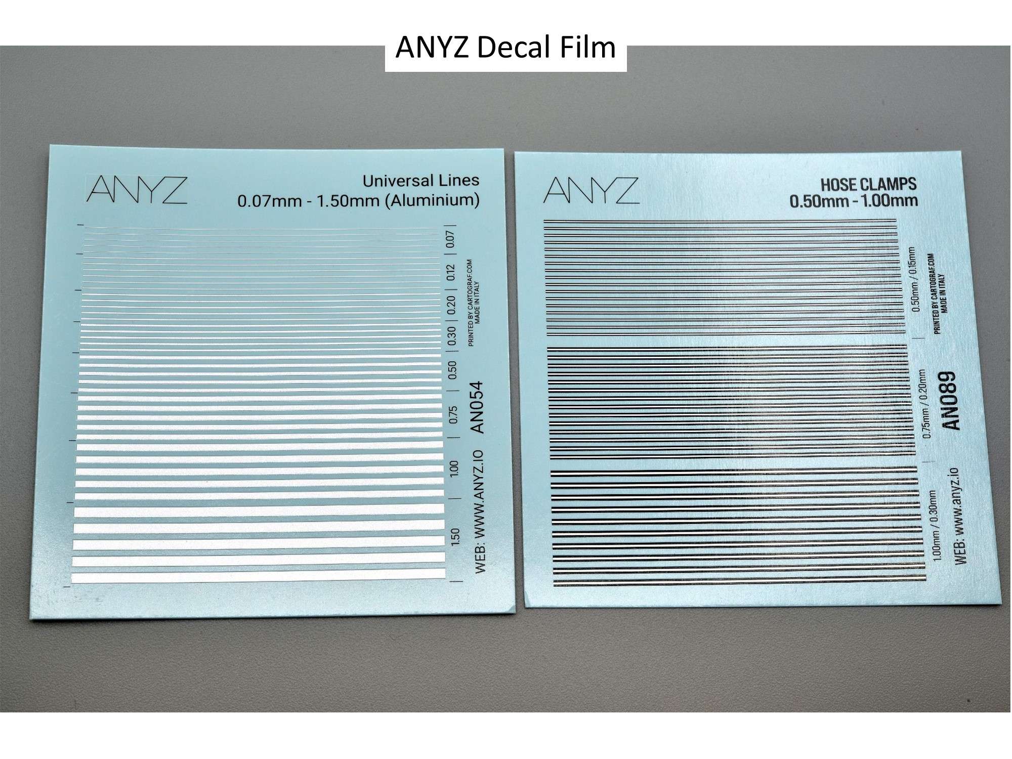
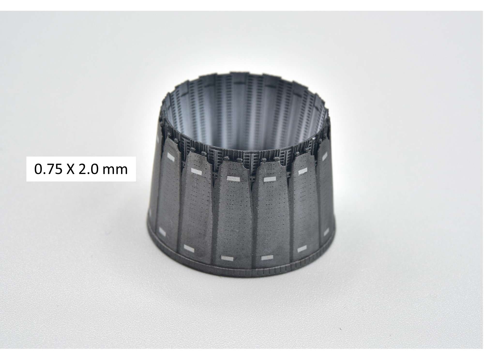
Recall that I was looking for something to sort of replicate all those small “No Push” placards that are on the engine nozzle petals. What I found is a compromise of what I knew would work, but a bit too shiny for accuracy. Since you can’t read what the placard says on 80% of the P&W nozzles, even at 1/1 scale, I wasn’t too worried about 1/32 scale. I ruled out paint masks because you can’t fix flaws and paint bleed without making a mess, so I used some Aluminum ANYZ decal film that I’ve used many times before, but in other colors like black, red and yellow. While I was at it, I bought some new hose clamp film that will come in very handy with my next build, which is likely the 1/24 Airfix Spitfire Mk IX, if my new JetMads 1/32 AJ37 Viggin doesn’t call me to another jet!

After carefully cutting the aluminum decal film, applying the “placards” and spraying a dull coat, this is what you get. Like I said, the placards are a bit too shiny and pronounced, but I think the overall look is still an improvement on overall accuracy. I’ll see if I can dull them up a bit without wrecking them, but at this stage I’m really getting tired of showing this nozzle time and time again, which is entirely self-induced!
On to other things….
Cheers,
Chuck
-
Thanks Niels! I notice that this panel is on the other side of the kit as well, so I assume that I should delete them both? Also, just down from this panel and hidden by the horizontal stab (of course!), is the position light on both sides, which most modelers paint silver from behind. In Jake's book (P. 21), however, they are mostly red. Anybody know or have a good pic from above?
As for the adhesion of the metal stiffeners, I have already added CA glue to the small ones at the front, while the rear ones appear to be quite solid. It is my hope that when I spray Mr. Metal Primer (X-22?) on them, some of it will wick underneath, adding to the adhesion. Further coats of primer and paint should help as well.
Cheers,
Chuck
- scvrobeson, JayW, Derek B and 1 other
-
4
-
April 9/24
Lots of small updates, but mostly an introduction to 7 different after-market items you might not be aware of for this and the Block 50 kit.
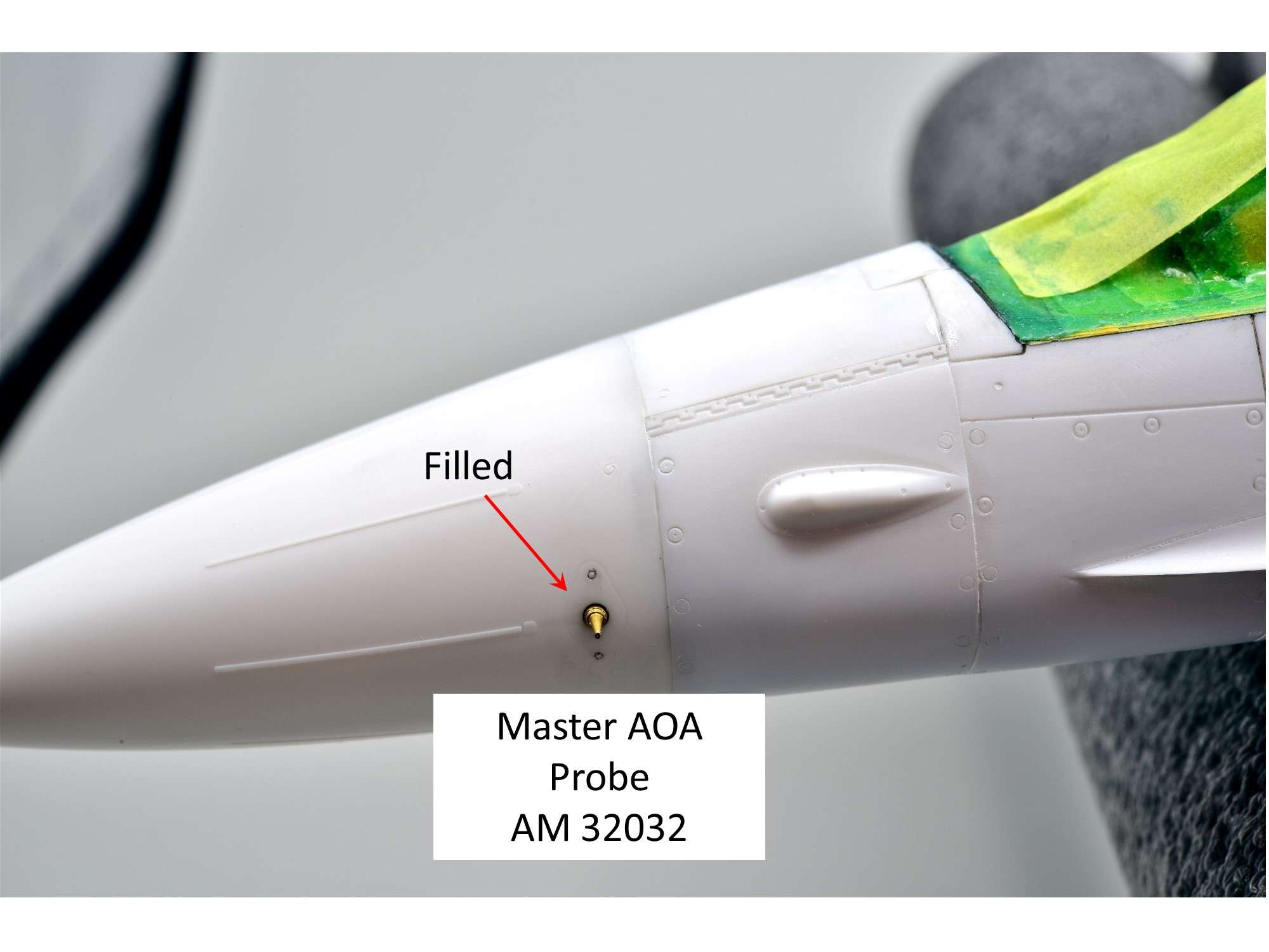
First some housekeeping, to remove that panel line around the AOA probe on both sides of the nose cone. While it’s usually stained this way due to the protective cap that's placed over the probe when parked, it isn’t a real panel line, so I want to remove it. Same thing holds true for the Tamiya F-15 kits.
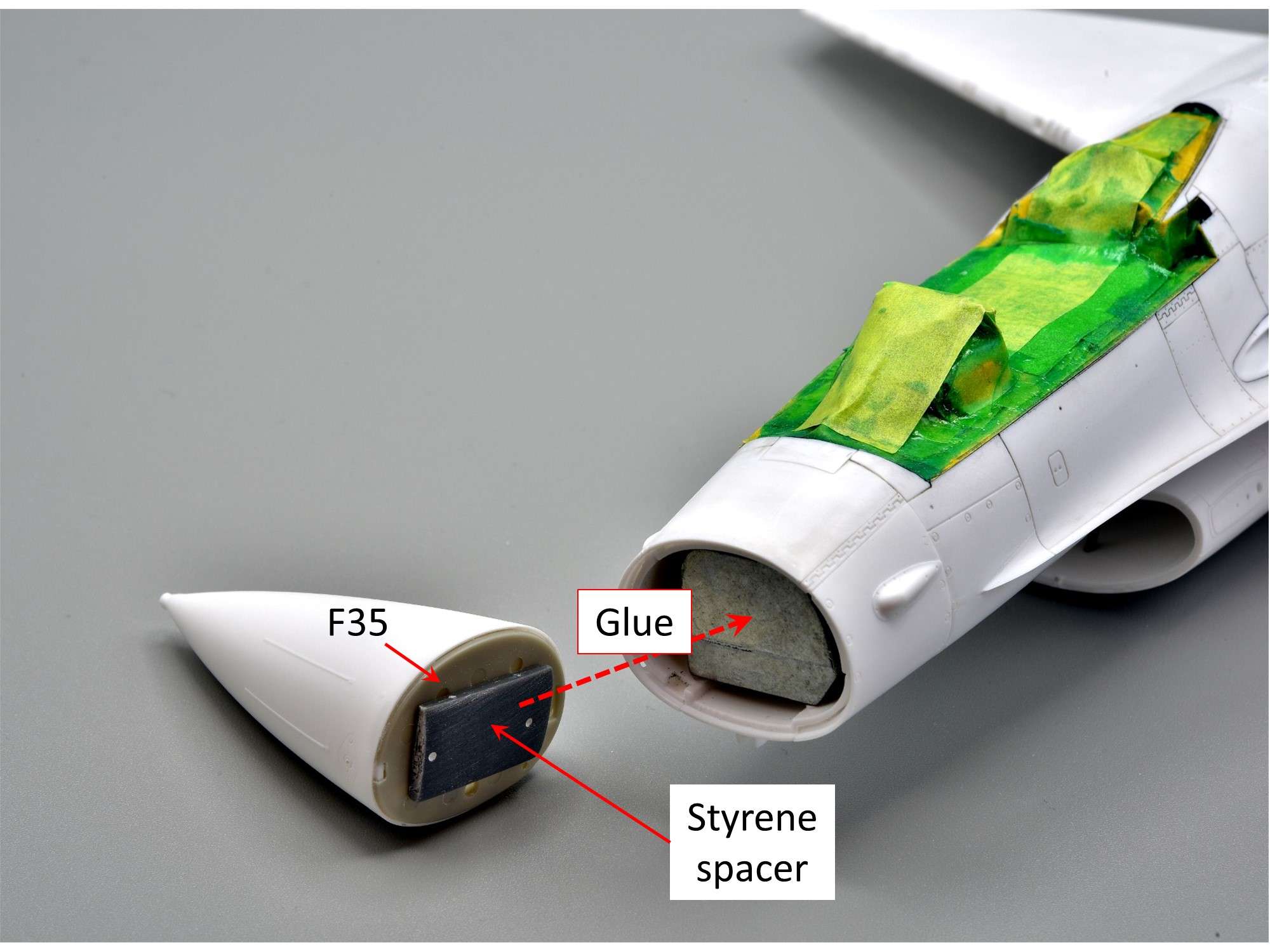
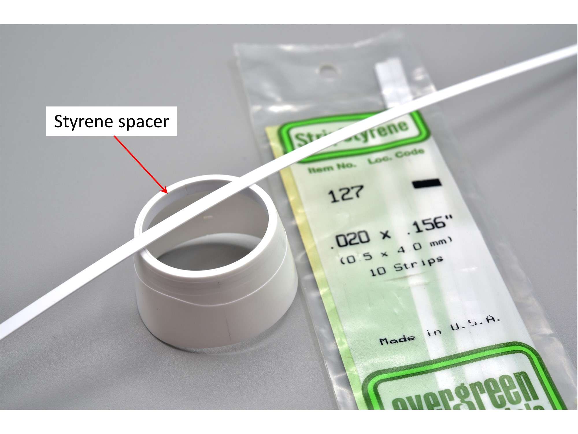
This kit has a removable nose cone to show off the radar stuff like the Block 50 kit, but it doesn’t have the radar screen anyway, so it should be glued into place instead. The nose cone join isn’t very strong as a result, so to reinforce the join I glued Part F-35 to the nose cone first, then a styrene spacer from scrap that was sanded down to size to fill the gap behind it. I used thick CA glue to weld it to the metal weight at the front, which gives you about 5 minutes to wiggle it around to get the best fit from all sides and angles with ordinary Tamiya ETC applied around the margin.
The nose cone join was then sanded down where needed, with eroded fastener detail restored with the usual tools to do so, like a Mega Tool for the big fasteners. For the AOA probes I cut off, I’m using Master brass replacements which I’ve used a few times before on my other jets. I think they really “kick them up a notch”.

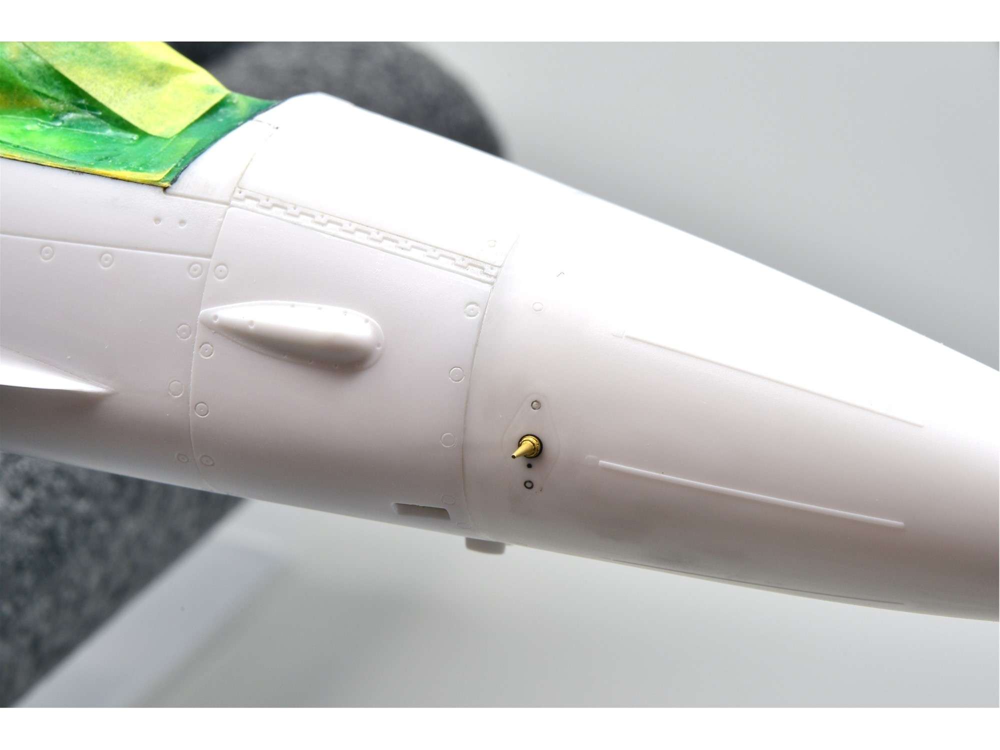
The other side. These probes fit into small holes that I drilled, so I can leave them off until the end of the build.
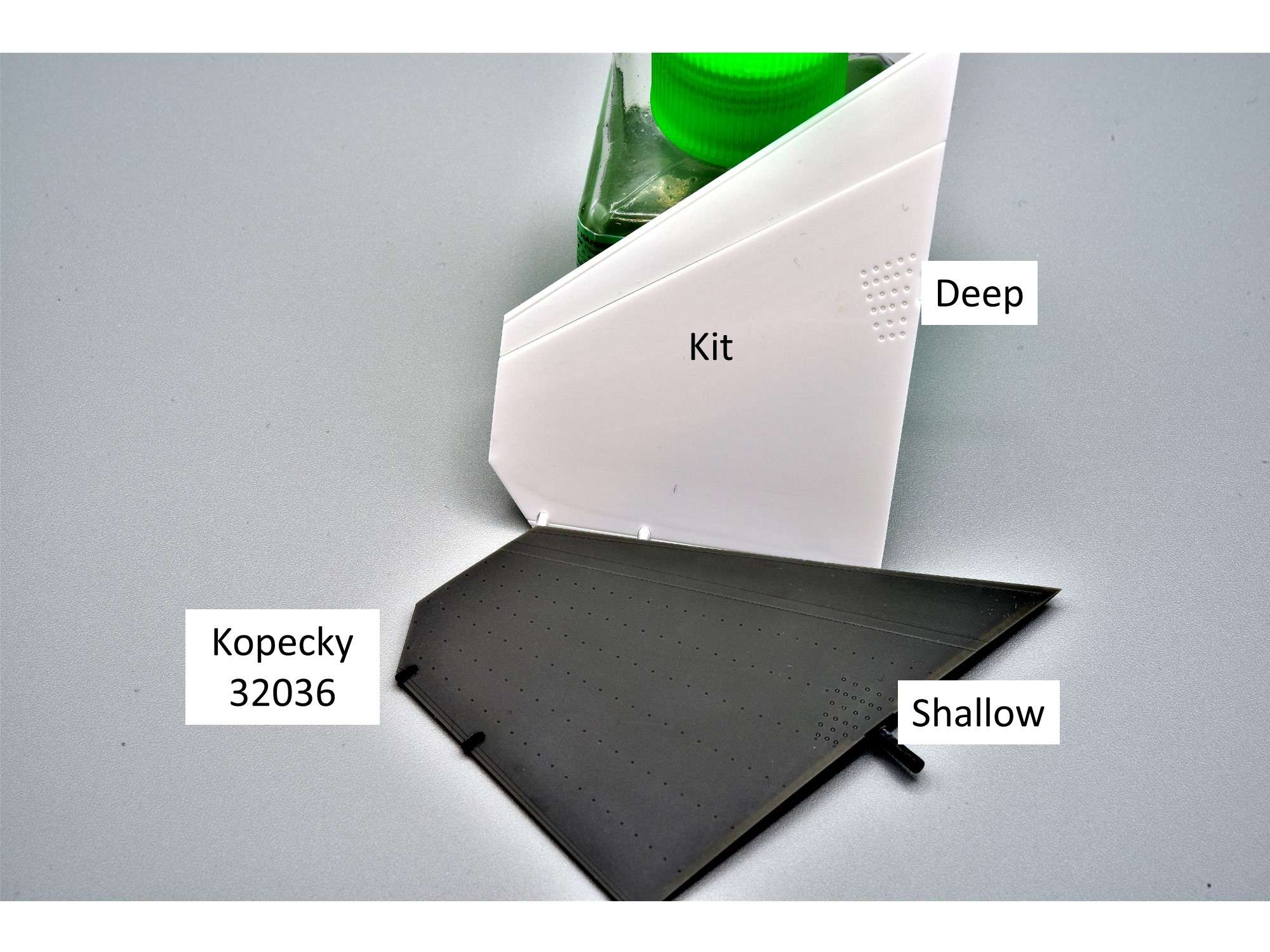
Another addition to this build is Kopecky horizontal stabilizers, which I heard about from our friend Marcel about 18 months ago, so I ordered a set for this future model. The Kopecky resin I’ve used so far is excellent and probably on par with ResKit, which is saying a lot! The service is excellent and their website is here:
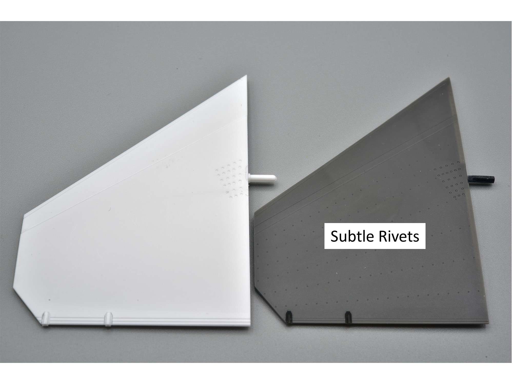
This set comes with nice subtle rivet detail, but if you want almost no rivets, they now make a smoother version (32028). Although most of these stabilizers are quite smooth, there are a few where you can clearly see the rivets like on Page 30 of Jake’s book, so I’m happy to stick with these instead. As usual, trying to photograph this snow-white plastic is a real struggle, but next to this dark resin, it’s even tougher. As you probably know, those moon craters next to the stab axle on the kit parts are way too deep, while the Kopecky rivets are at the surface where they should be.
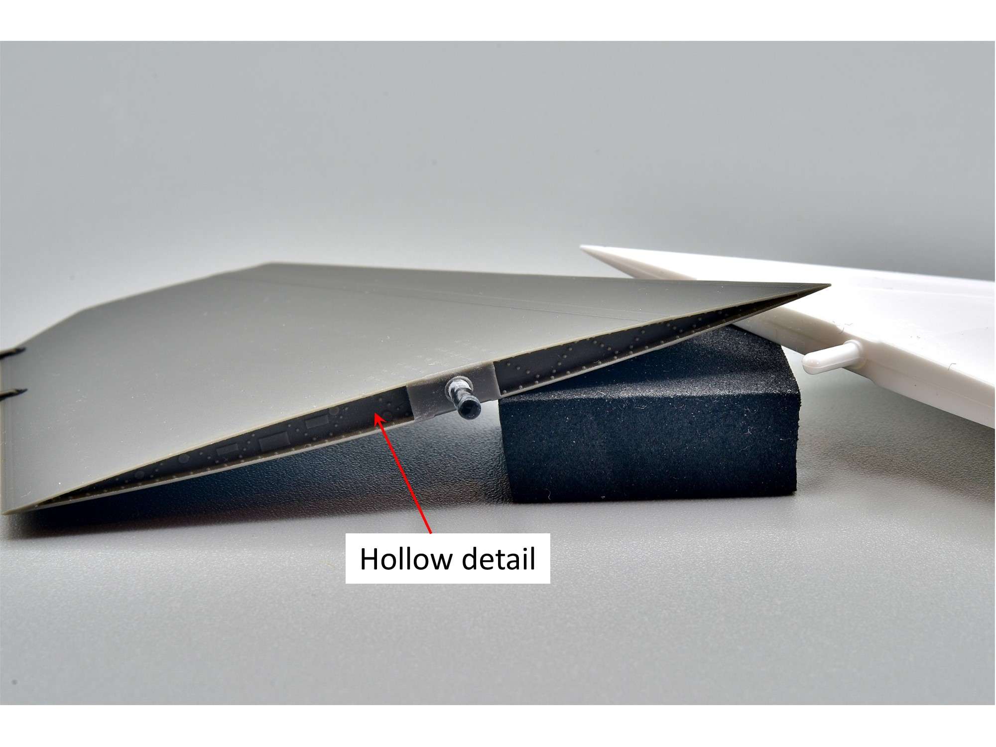
The Kopecky stabs also have really nice recessed hollow internal detail that is missing from the kit.
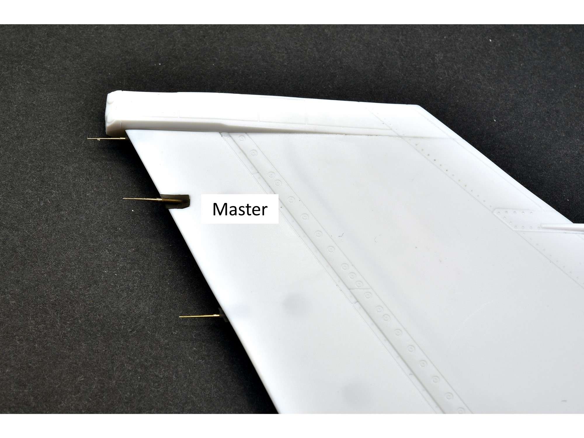
Even if you don’t care for the resin stabs, you should buy this kit for the super fine brass static wicks that come with it, also made by Master. The kit one in the middle sure looks crude and chunky when set next to them.
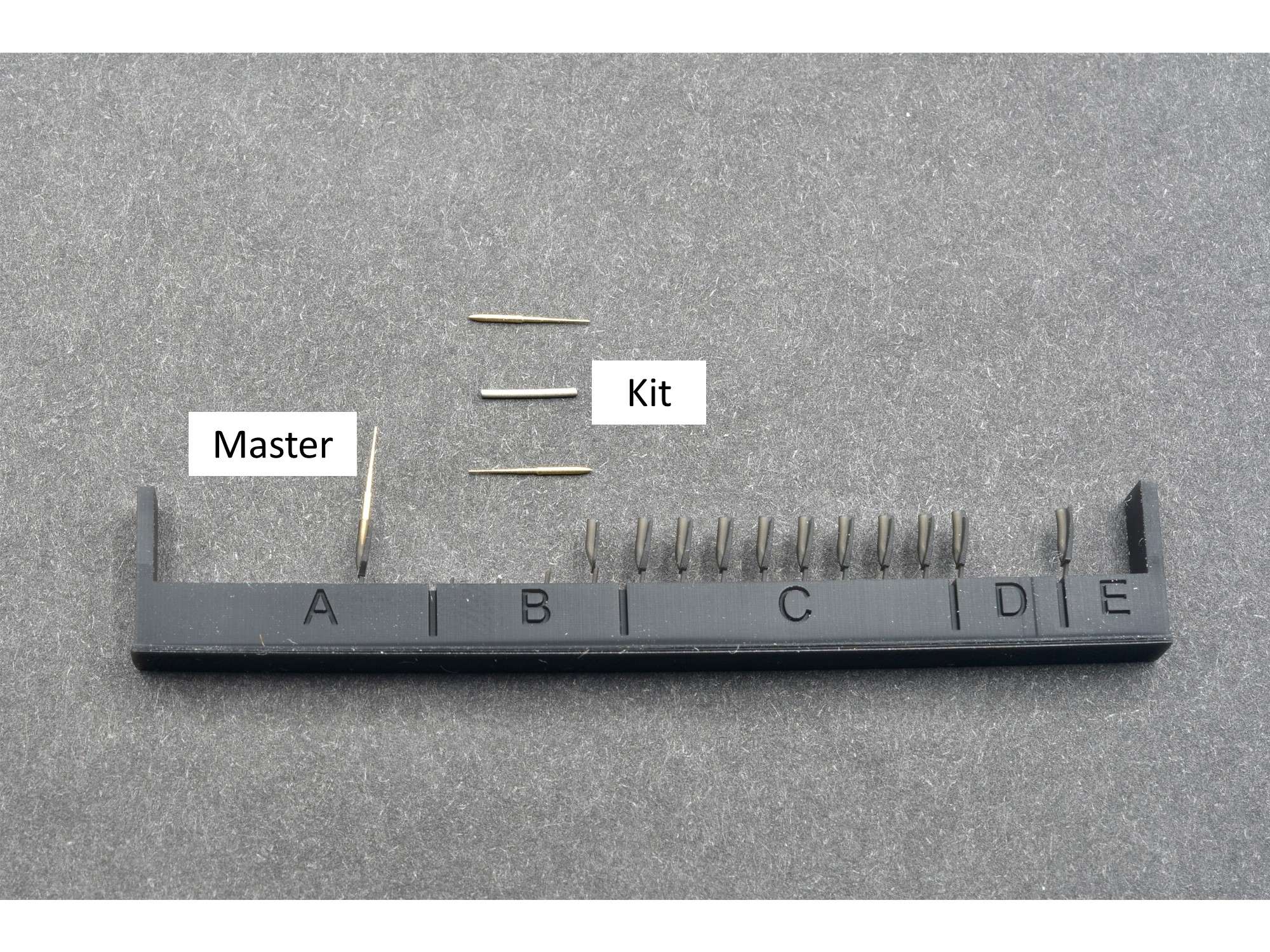
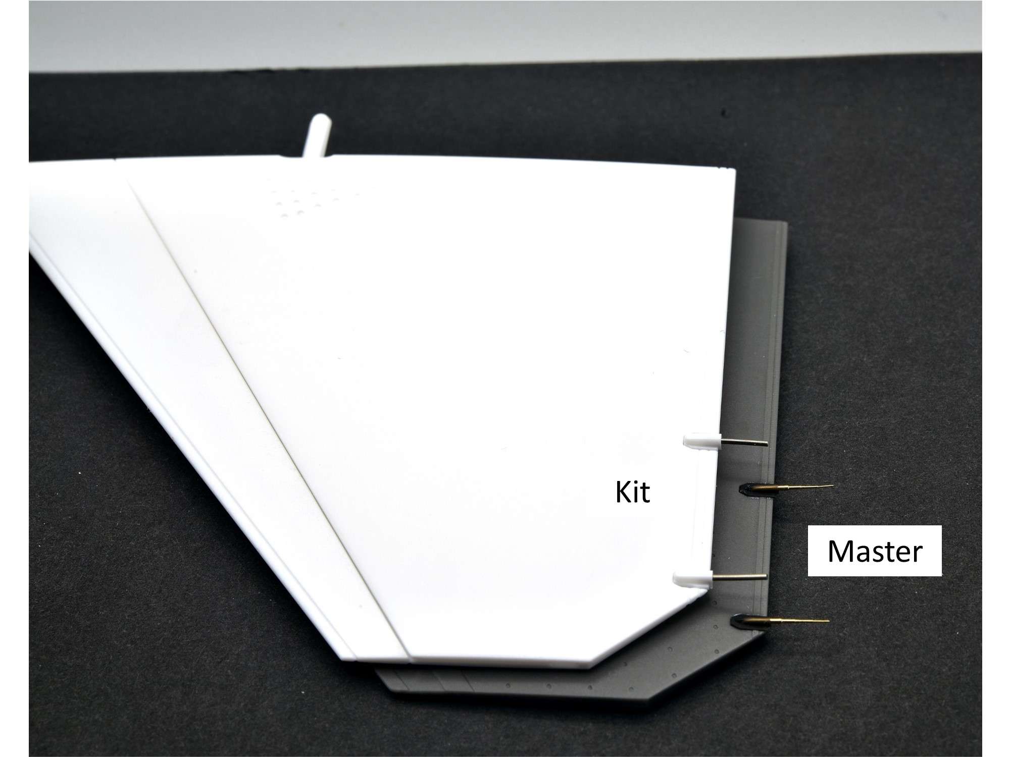
As an added bonus, there’s enough wicks for the vertical stabilizer and the rear tips of the wings. The little resin wick holders fit the kit parts perfectly.
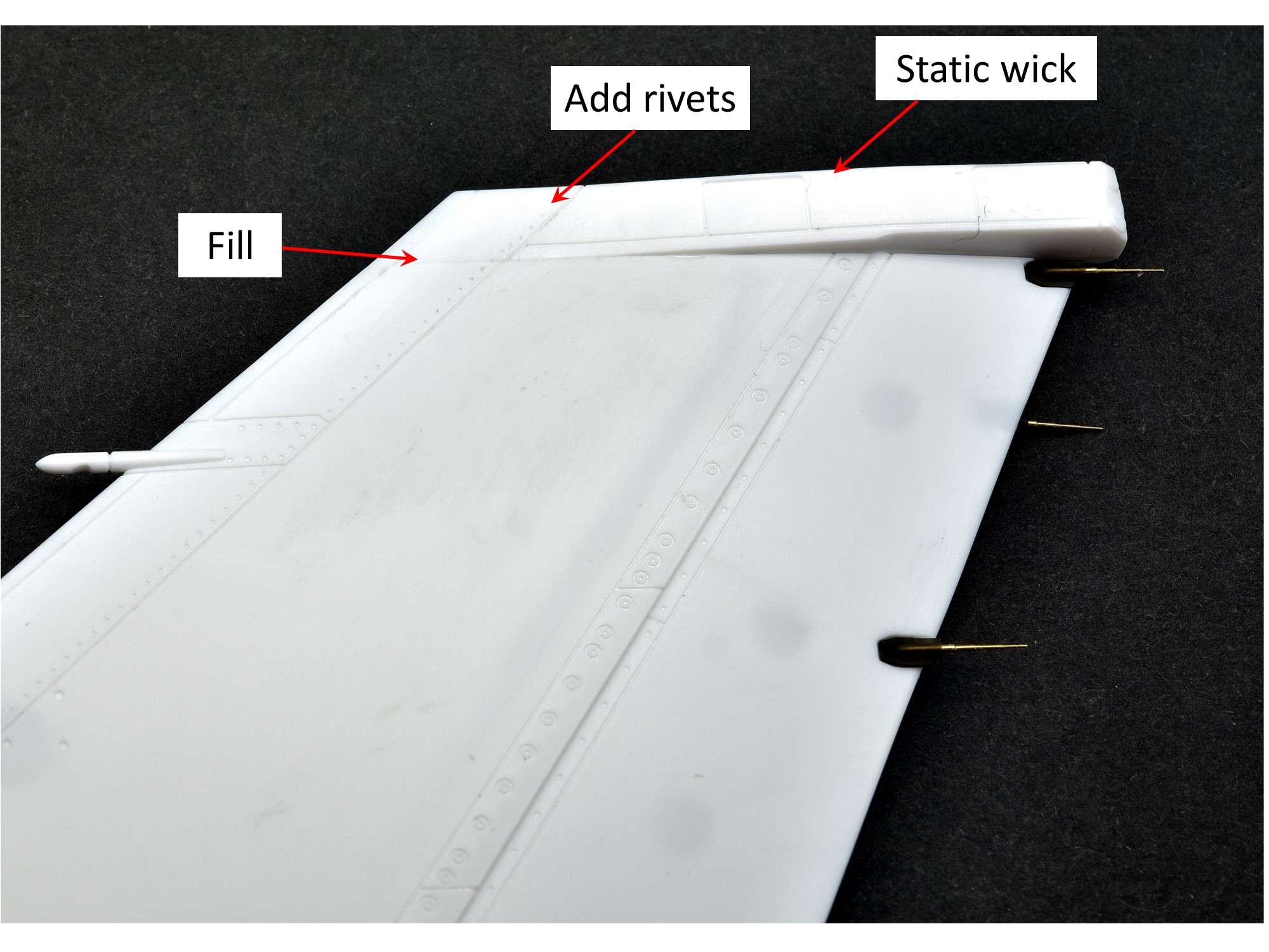
While we’re looking at the vertical stab, that top panel line at the front should be filled and rivet detail added, while a static wick should be added, right behind the top light assembly that will be added later.
Kopecky also makes really nice LAU-129 missiles rails, which thankfully come in a set of 4, because you’ll need all of them.
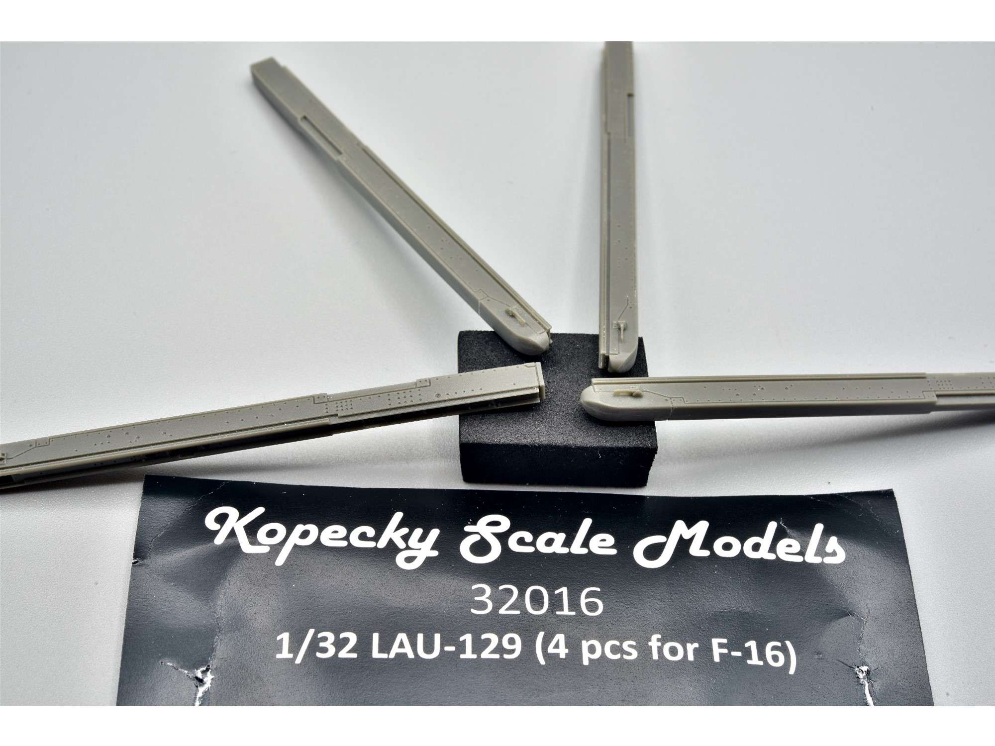
And a really detailed center-line pylon, which comes in two parts, just like the real deal.
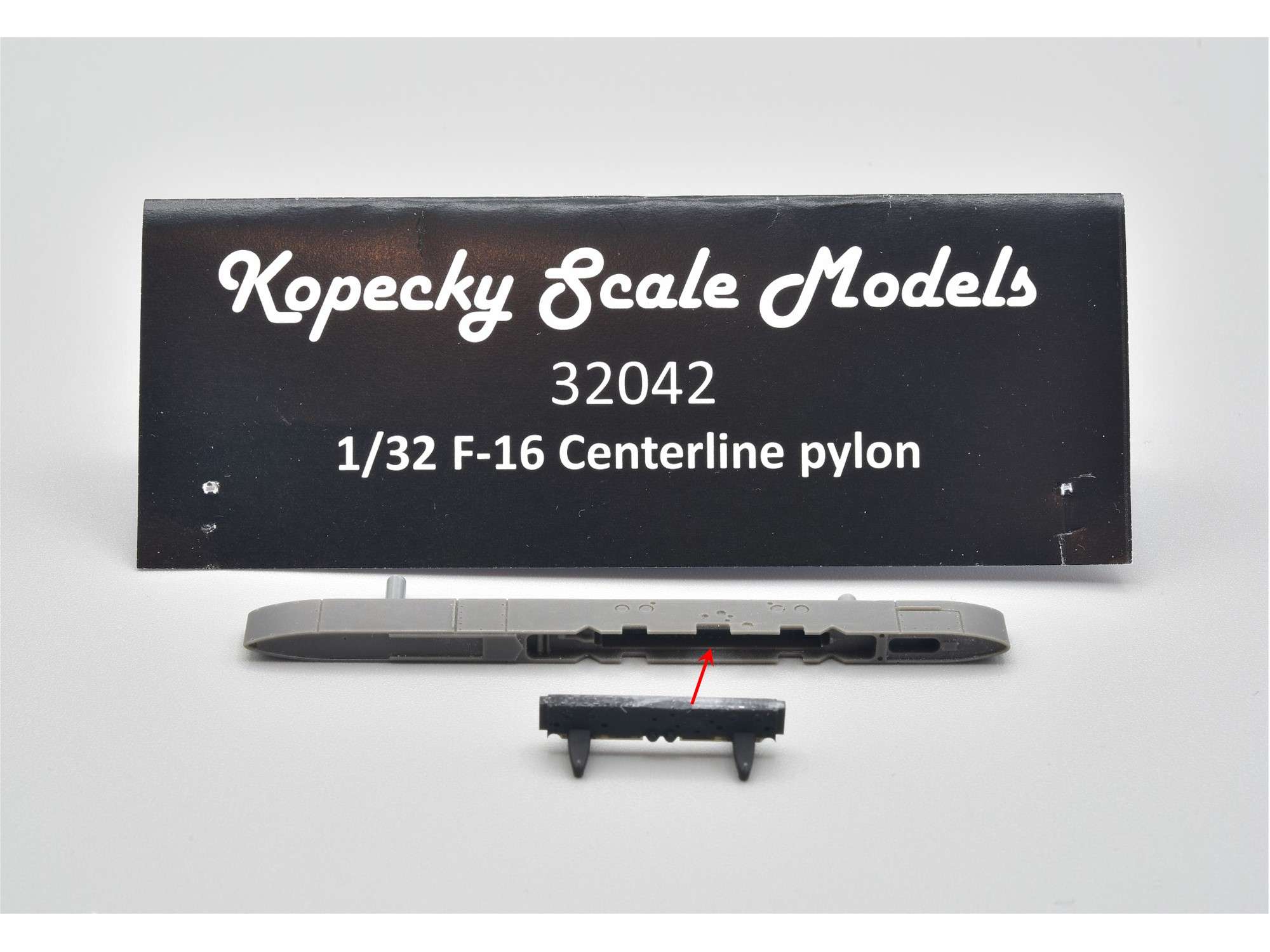
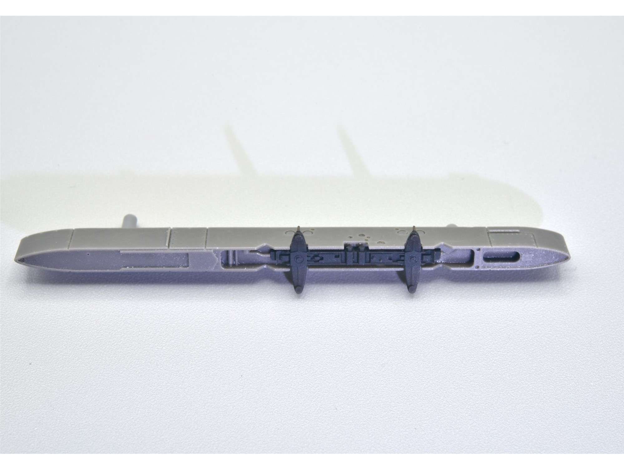
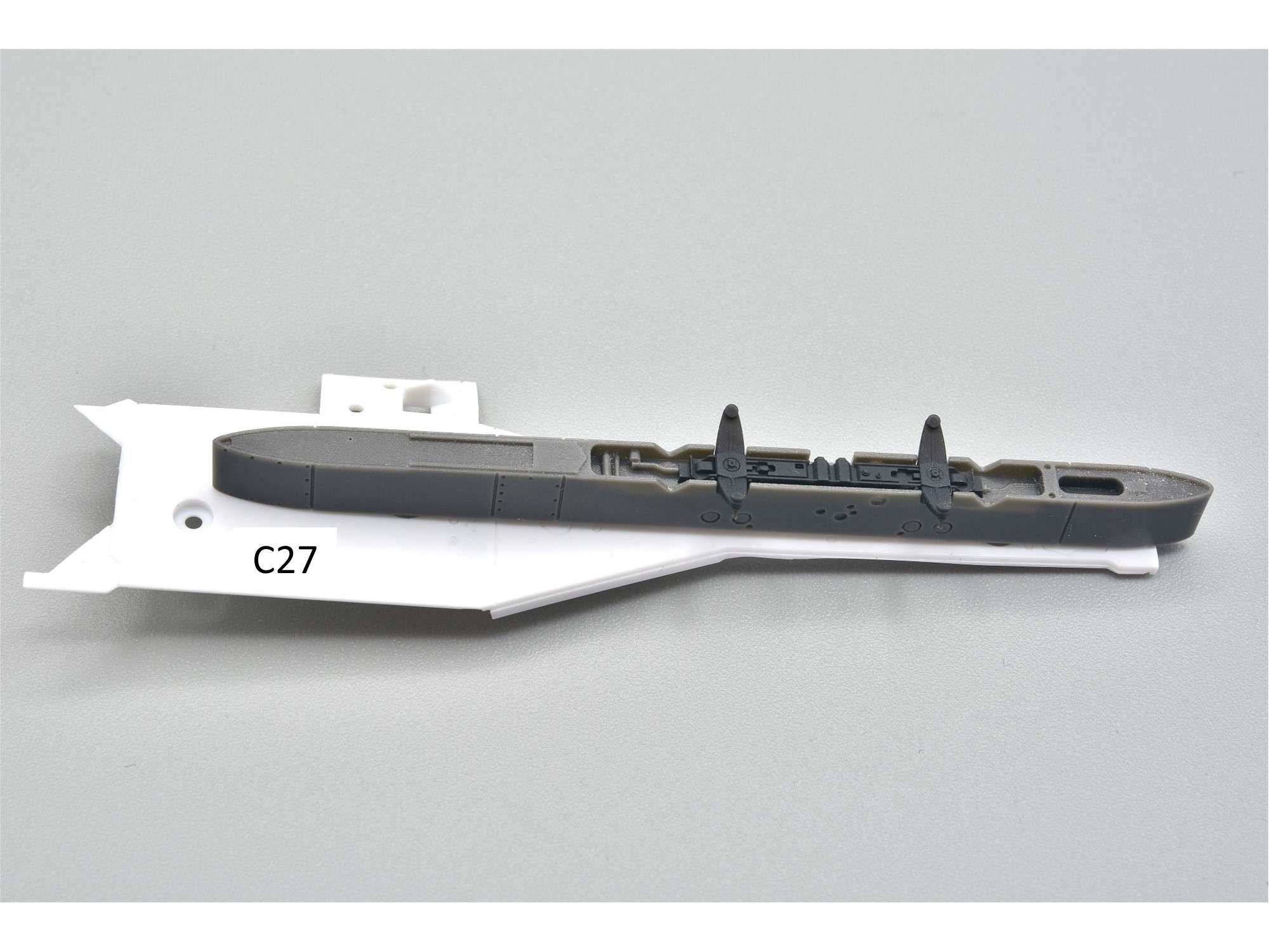
This will be added at the end of the build, along with the landing gear cover piece it attaches to, Part C27. It looks so good from the bottom, I may not add the fuel tank, so that you can see all the work I did in the landing gear bay unobstructed.
I have struggled for years to find a decent ACMI pod, because up until recently, the only resin ones available were poorly made and it’s hard to keep up with all the new versions that seem to come out every second year. Here’s the one on my subject, which I took in 2022.
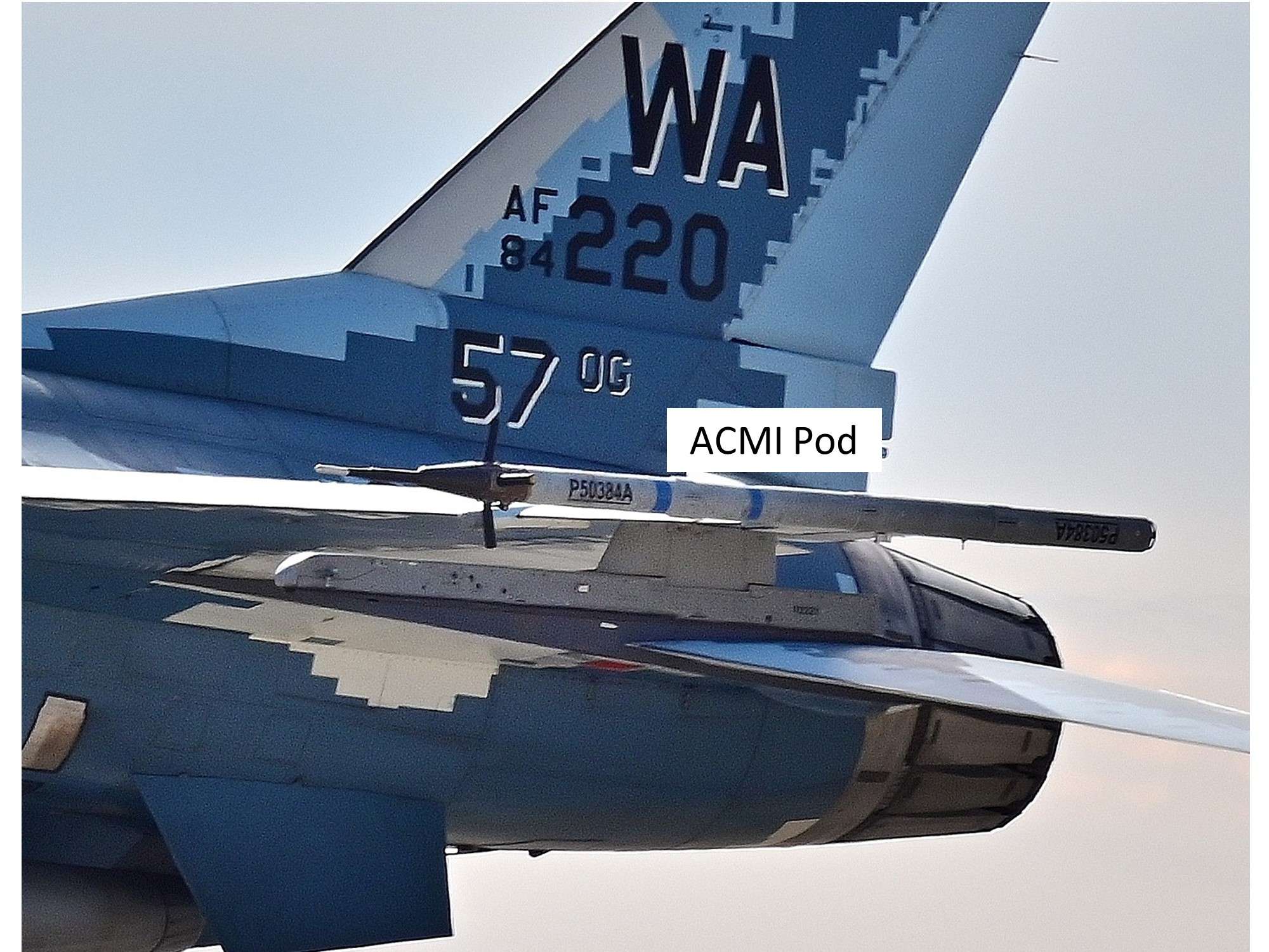
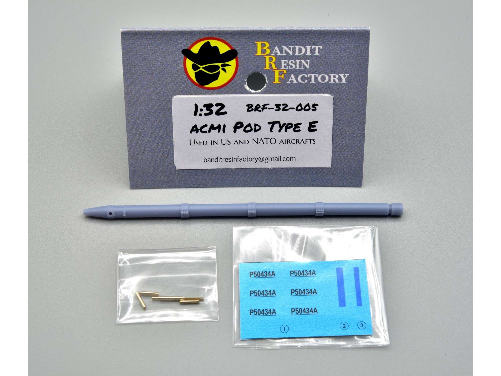
Thanks to 3D printing, we now have a few good options, like Phase Hanger Resin (1 ordered) and a new aftermarket supplier I found in the UK, Bandit Resin Factory. This supplier doesn’t have a full website yet, but they do have a Facebook presence, where you can see some of their products and contact the owner below, who will send you his catalogue.
Bandit Resin Factory (Facebook)
Apparently the ACMI pod above is a “Type E”, so I ordered 2 of them so that I had a spare for the stash. This is the nicest ACMI pod I’ve ever seen and it even comes with decals. Highly recommended!
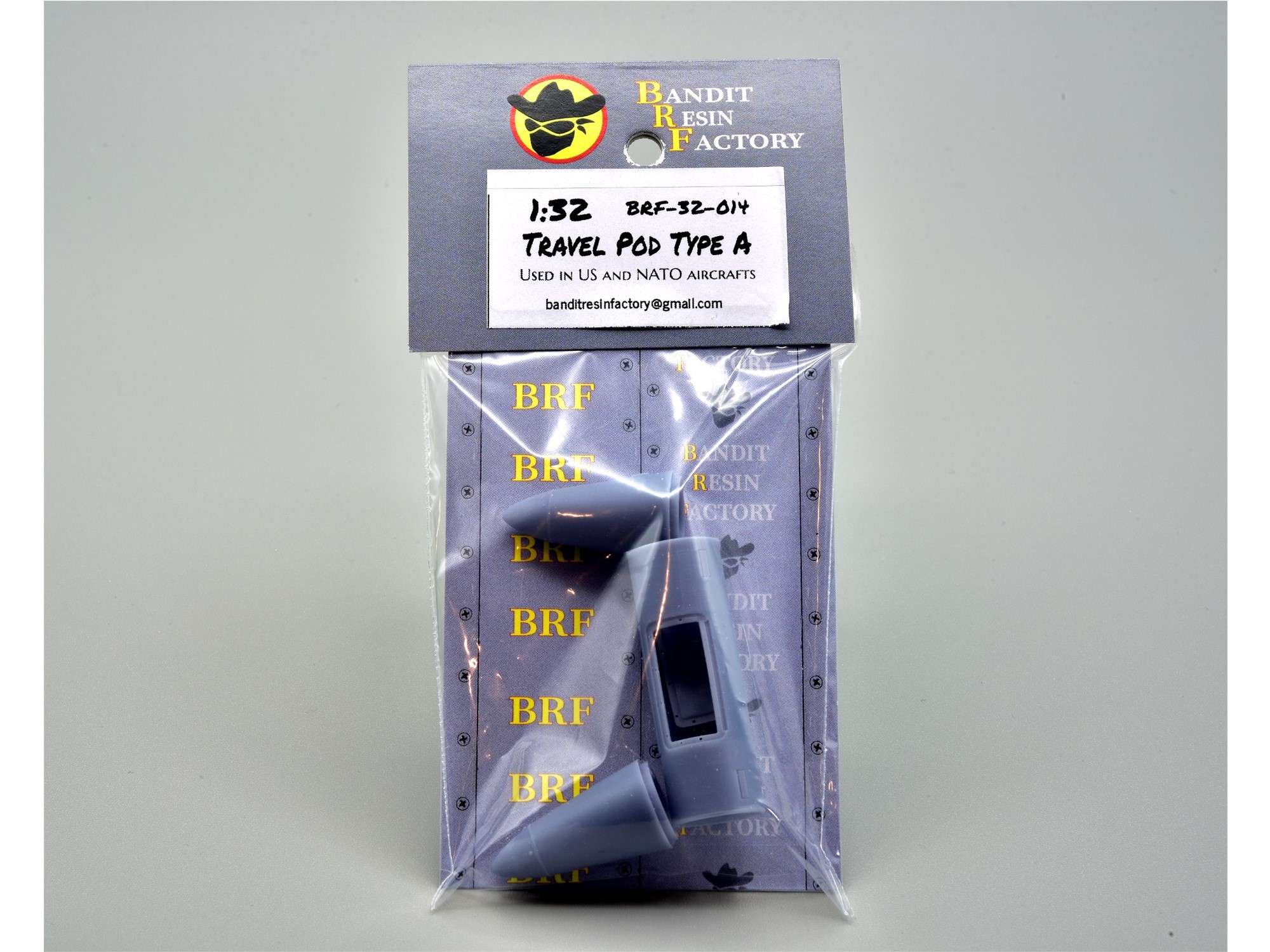
I also bought a travel pod that I’ve never seen before, which is also excellent with a door that opens. I didn’t open it yet, because I’m not likely to use it on this particular jet.
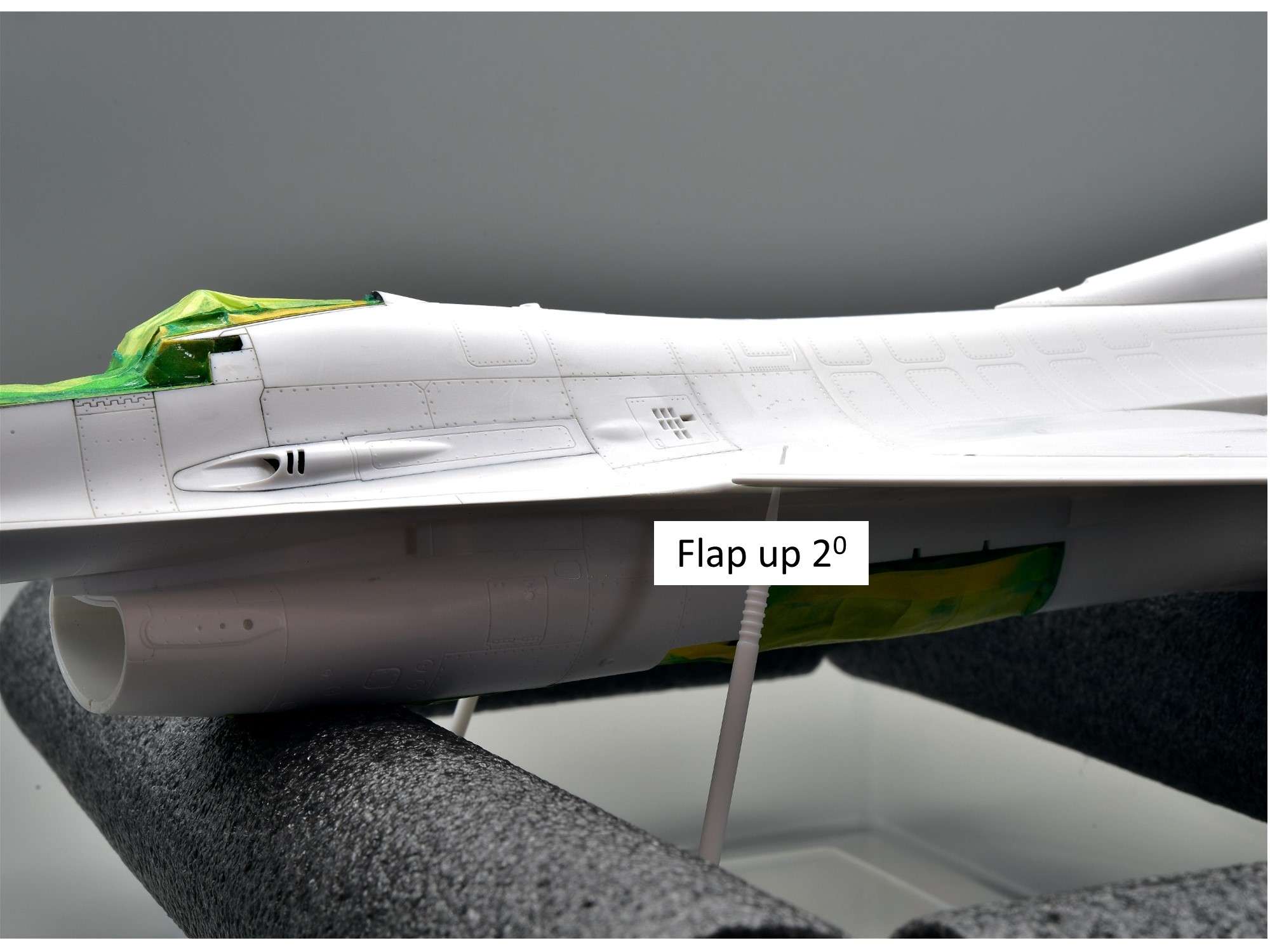
As mentioned before, the front flaps on F-16’s rest a few degrees in the upward position when parked for some reason.
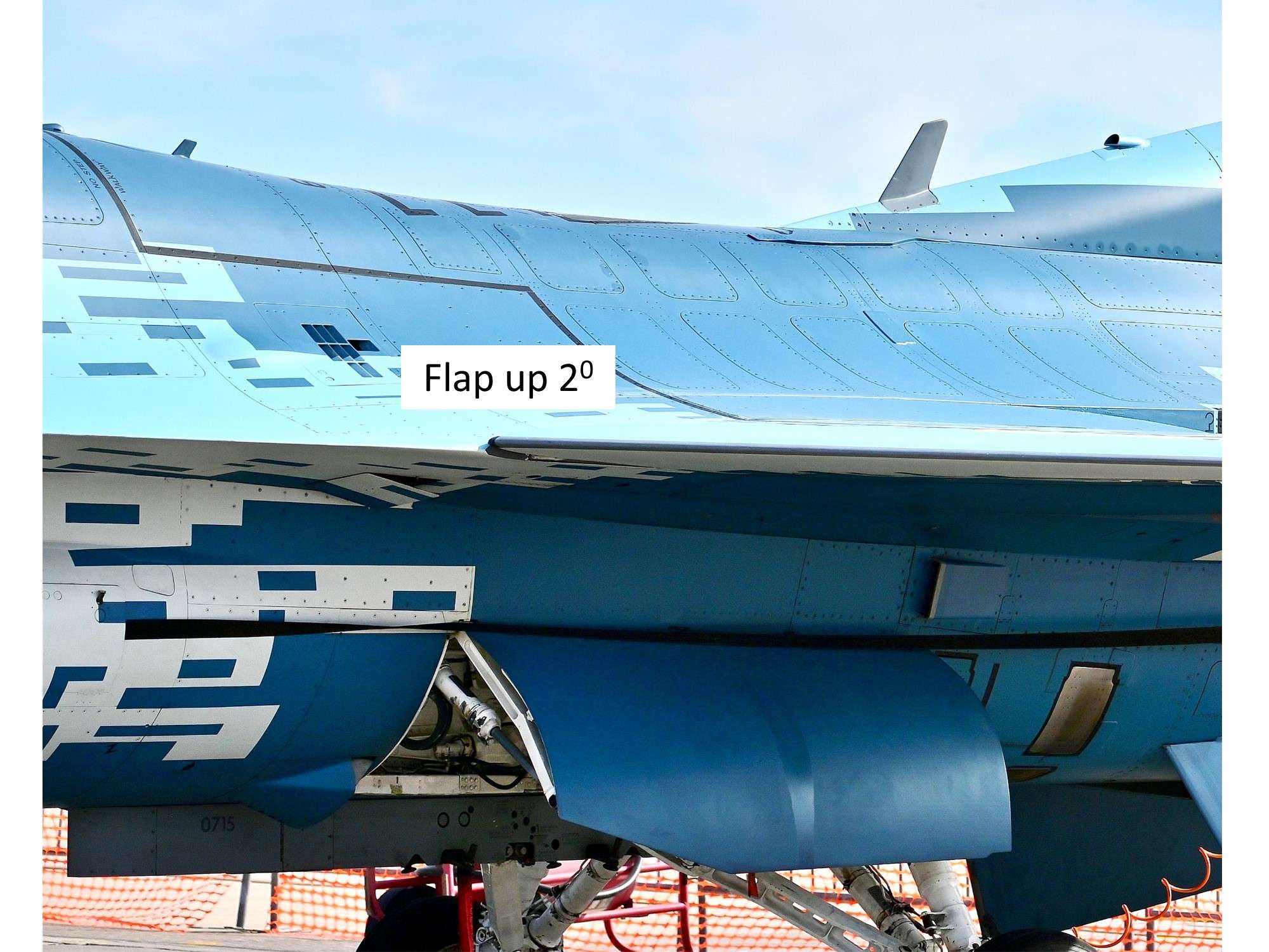
So I decided to cement mine in permanently now, just in case I struggled with the fit and angle later. With a microbrush holding up the flaps while the glue dried, they seem to be roughly correct.
Rear flaps were attached as well, but these ones can still move up and down.
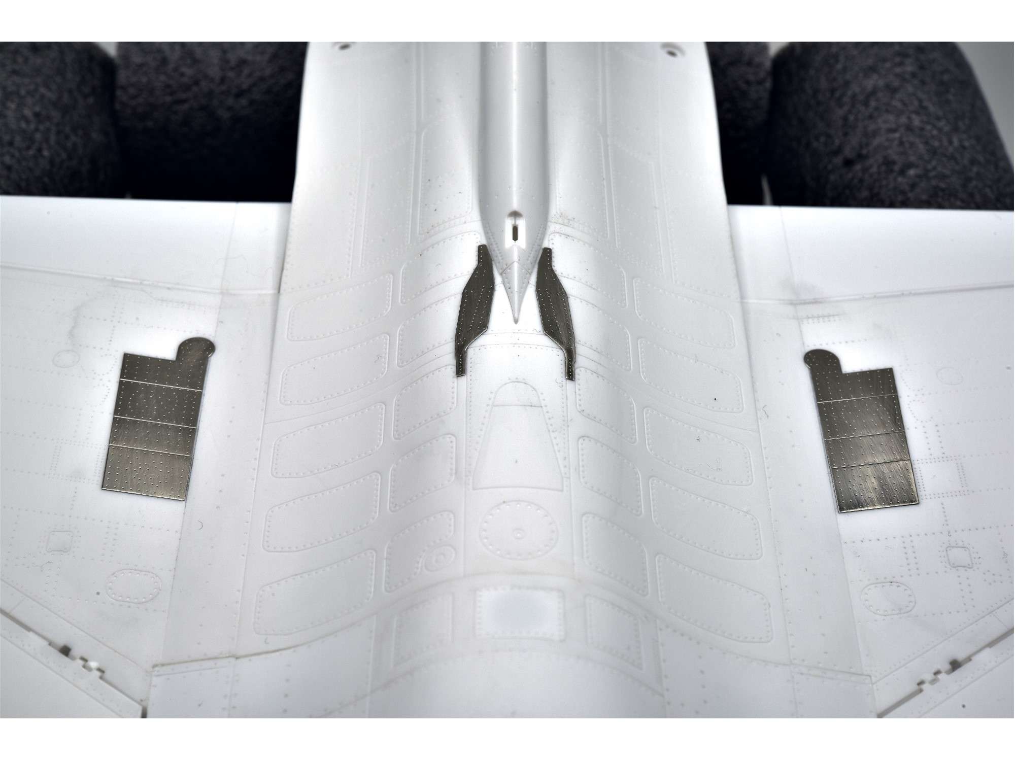
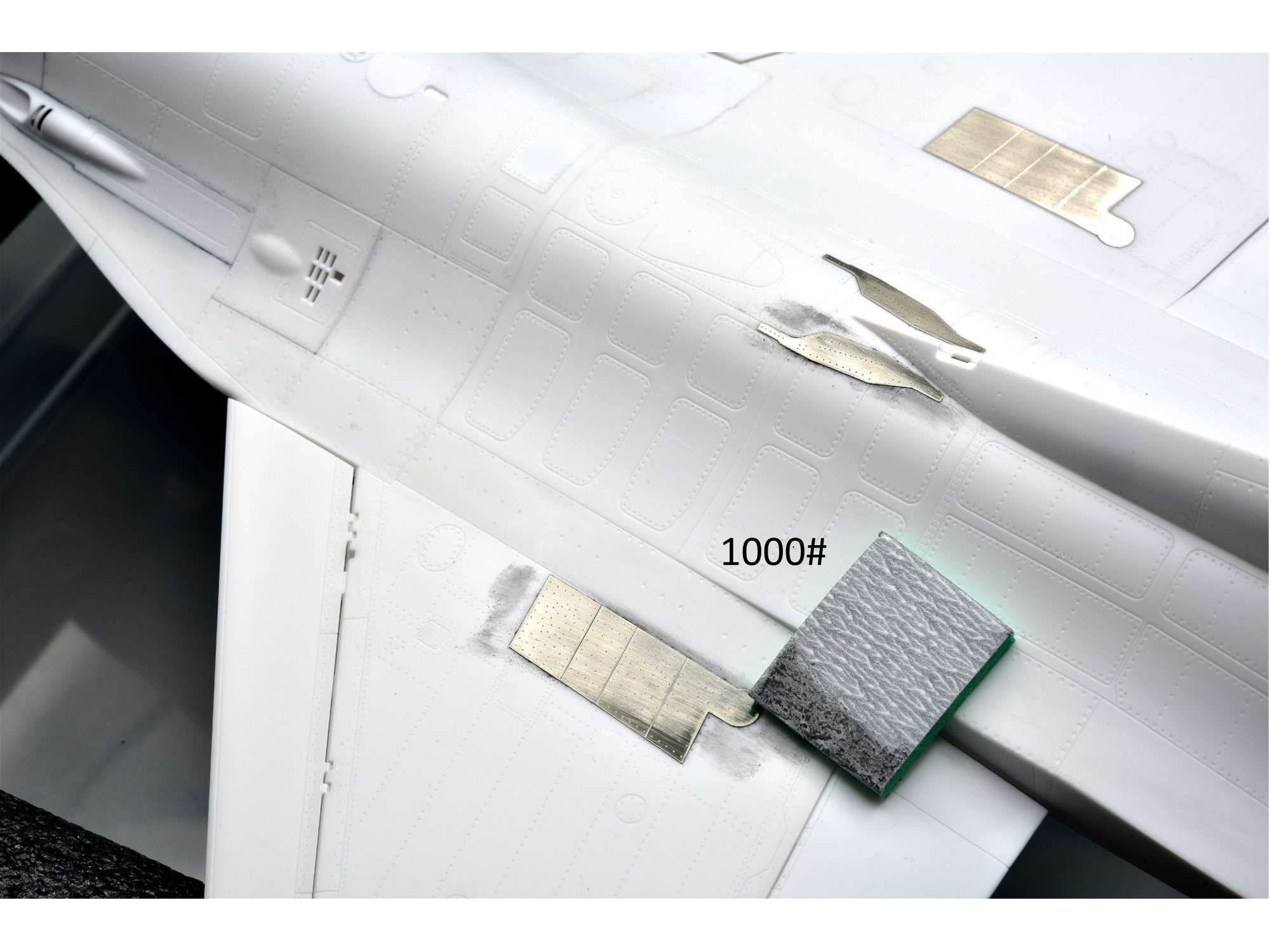
The next aftermarket parts I used were the CrossDelta external reinforcement plates that I showed earlier, which for Block 25 and Block 32 Vipers have the “lawnmower blades” to reinforce the vertical stabilizer base and the big 5-piece plate at the wing root to reinforce the fuel tanks. Tamiya includes a decal set to replicate these plates, but they are too thin and the rivet detail won’t show, unless you leave them unpainted white. I thought these CrossDelta plates would be metalized plastic, but they are actually made from real metal and are self adhesive.
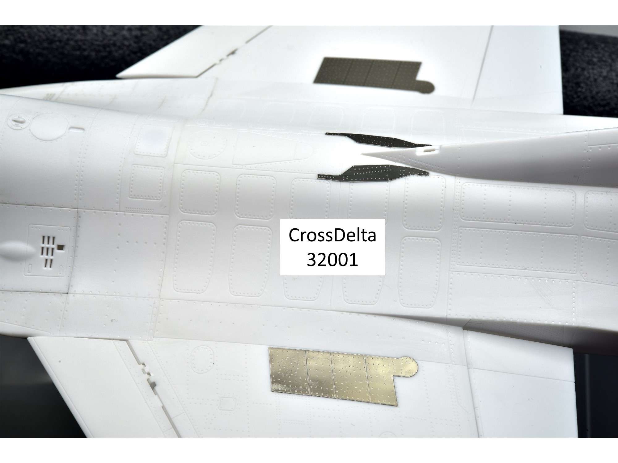
Tough to see on the white plastic, but this is where they belong based upon the instructions and Jake’s book (P. 23).
Since they are super glossy and metal, I scuffed them up a bit with 1000# sandpaper to help with paint adhesion, which isn’t too rough to leave scratch marks. I will need to use a metal primer as well if I want the paint to stick.
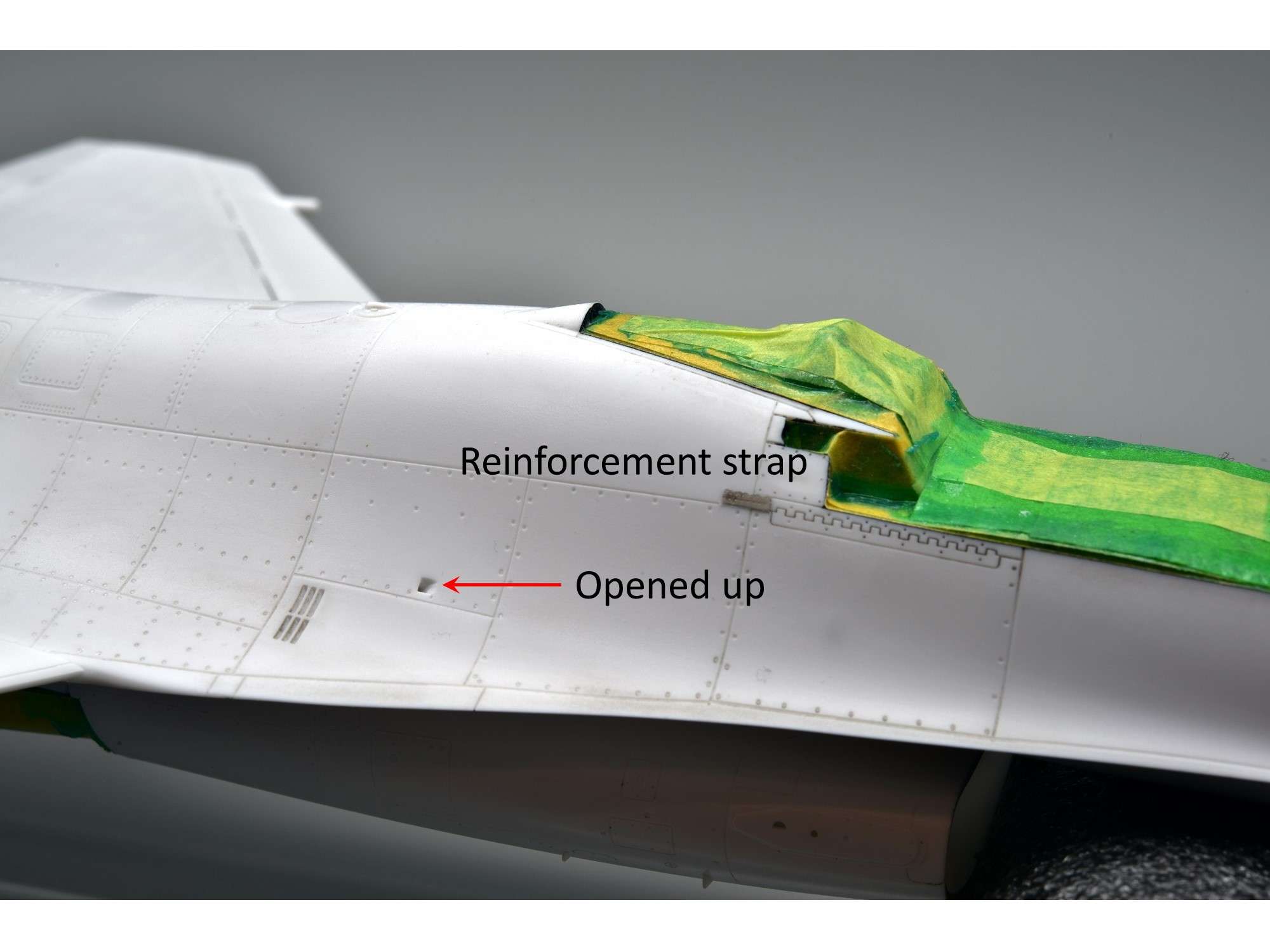
Not in the CrossDelta instructions or in Jake’s book, Block 25’s like my subject have a small reinforcement strap just below the canopy hinge on both sides, so I cut up one of the bigger plates to create 2 of them. Since they are so small, I wicked a little thin CA glue underneath them to hold them securely, then cleaned up the edges with CA glue remover.
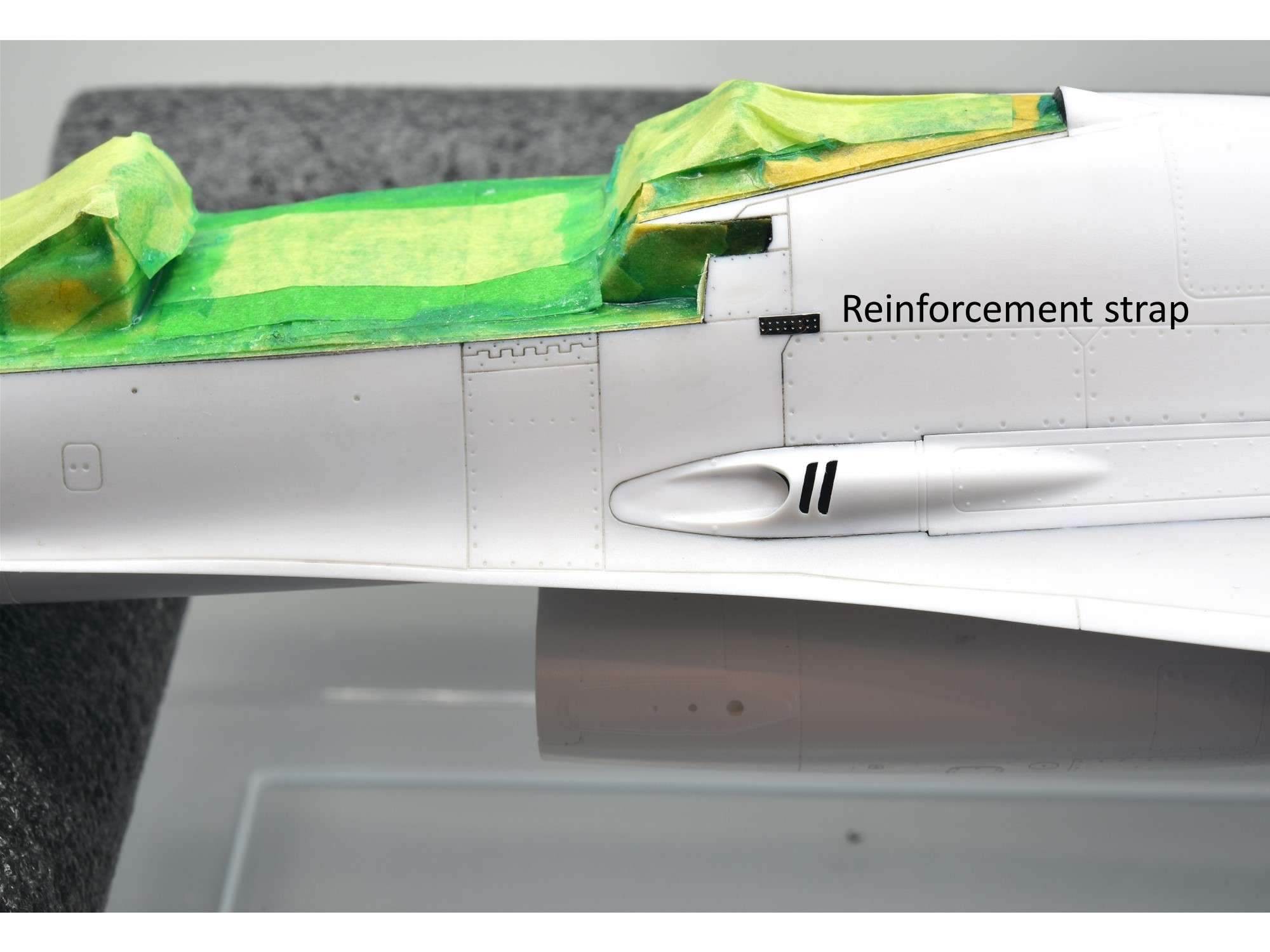
On the starboard side, the strap is just aft of the panel hinge. I also opened up that tiny vent on the side, which I should have done earlier from behind before the top fuselage Part B28 was cemented into place.
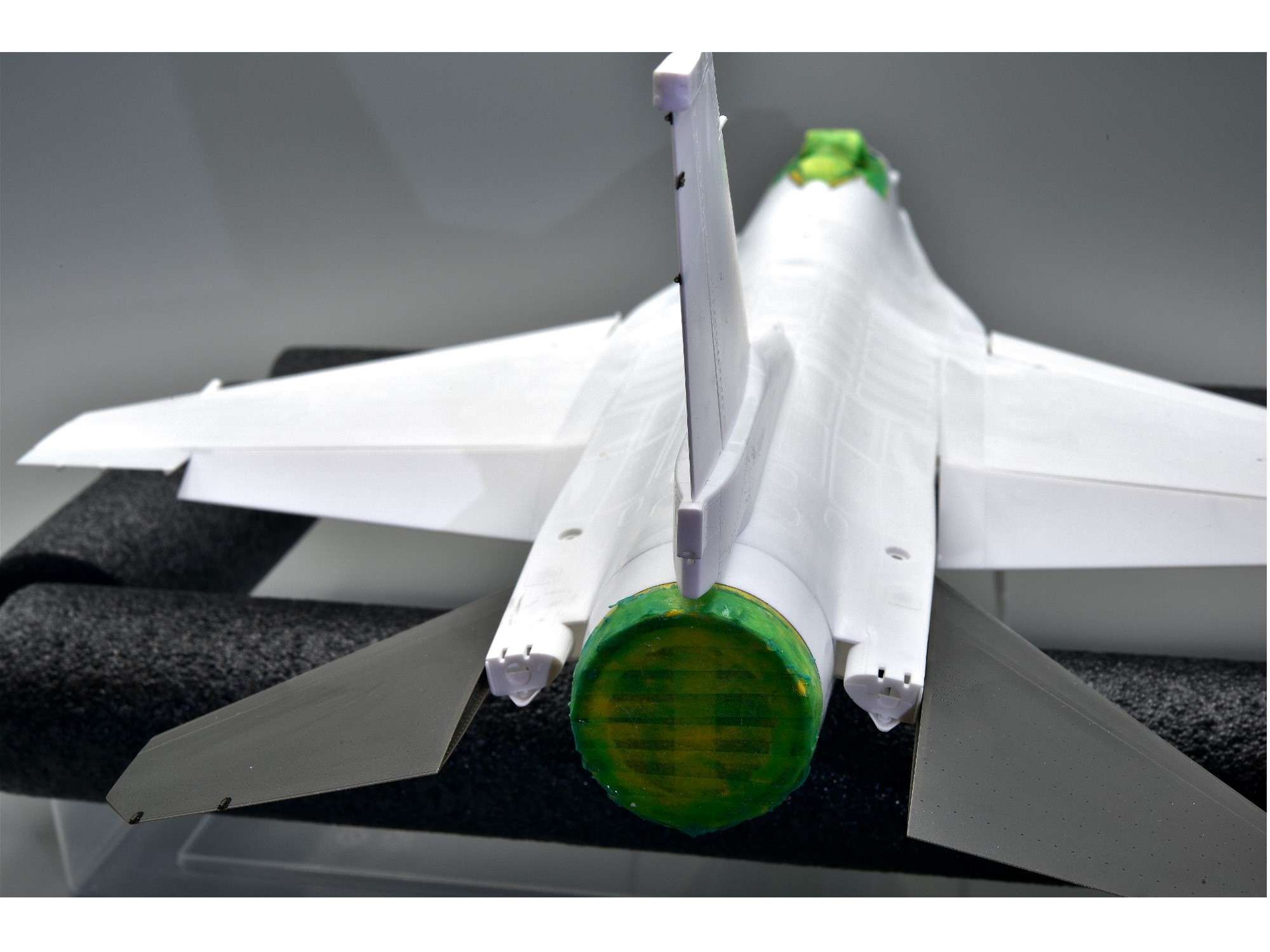
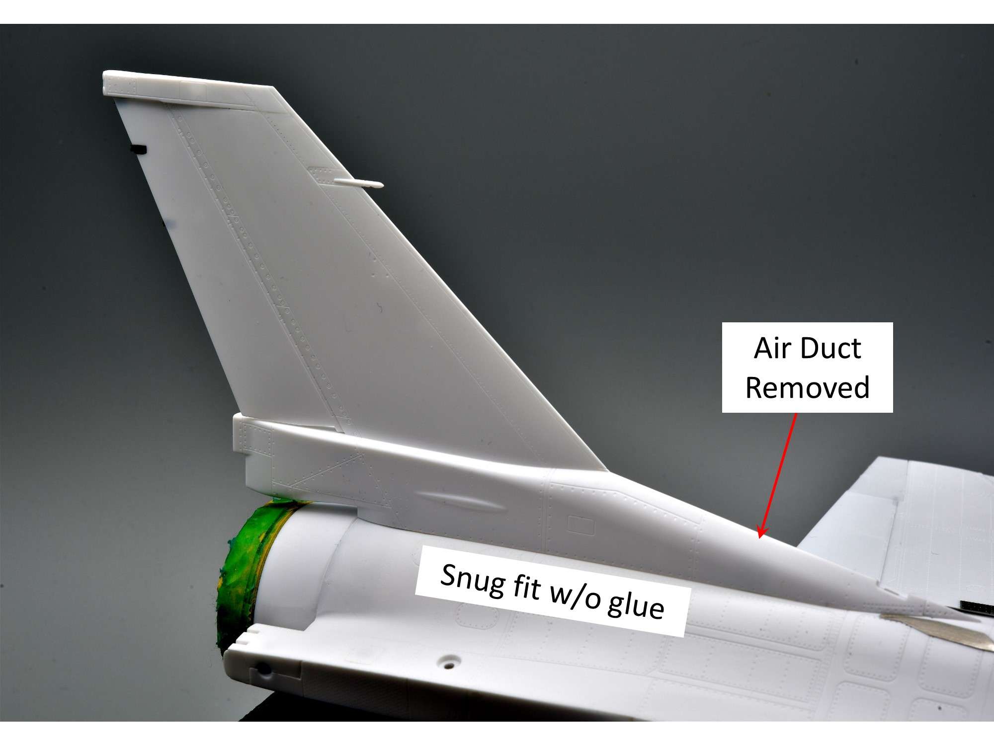
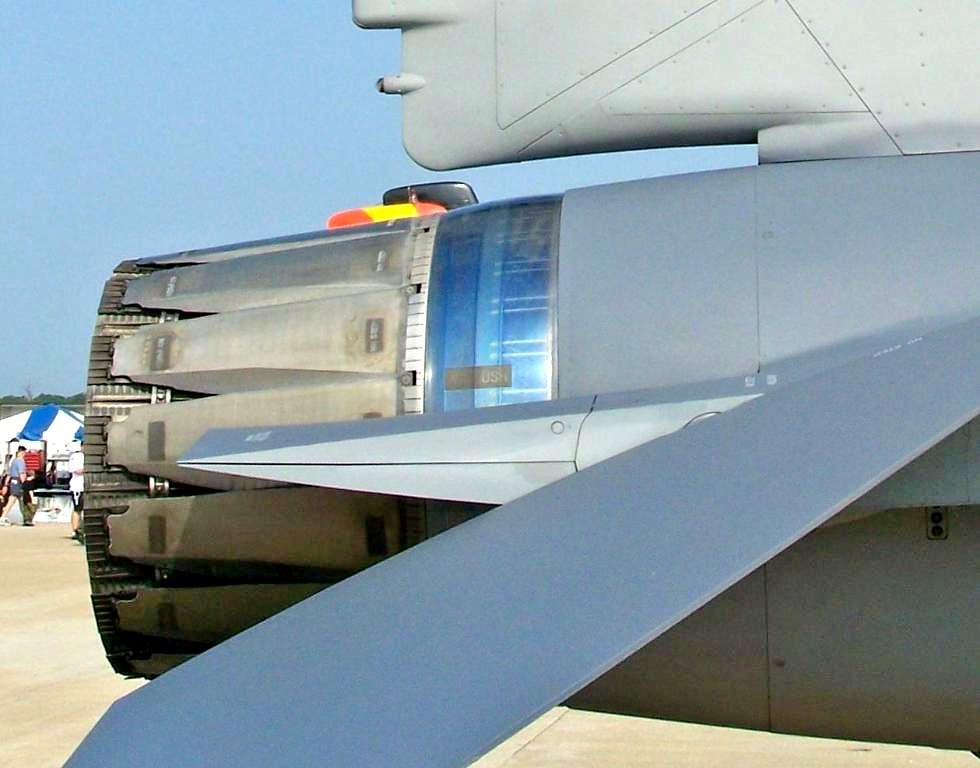
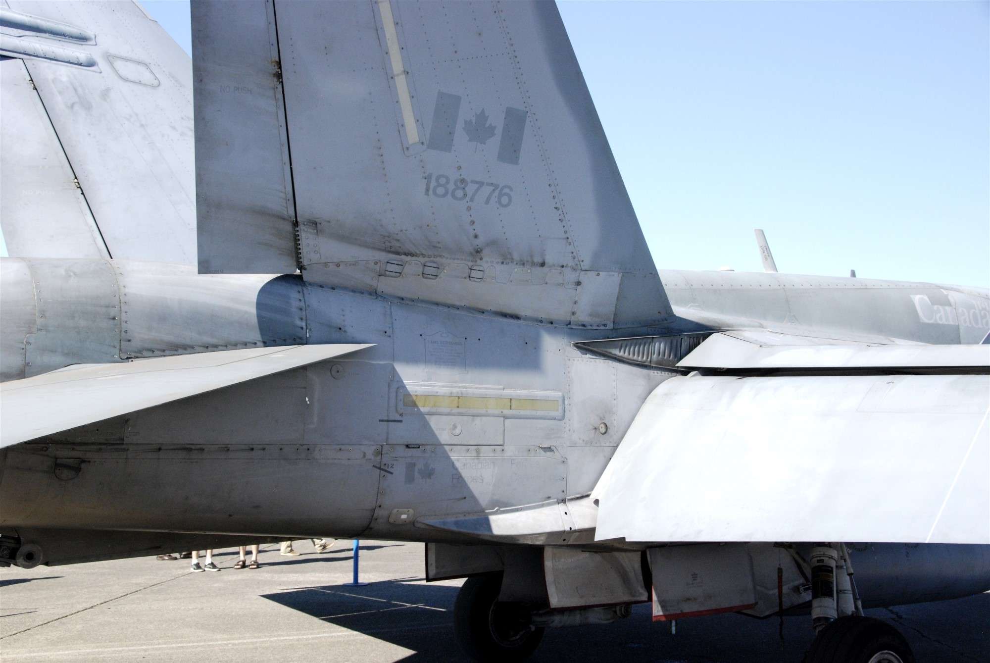
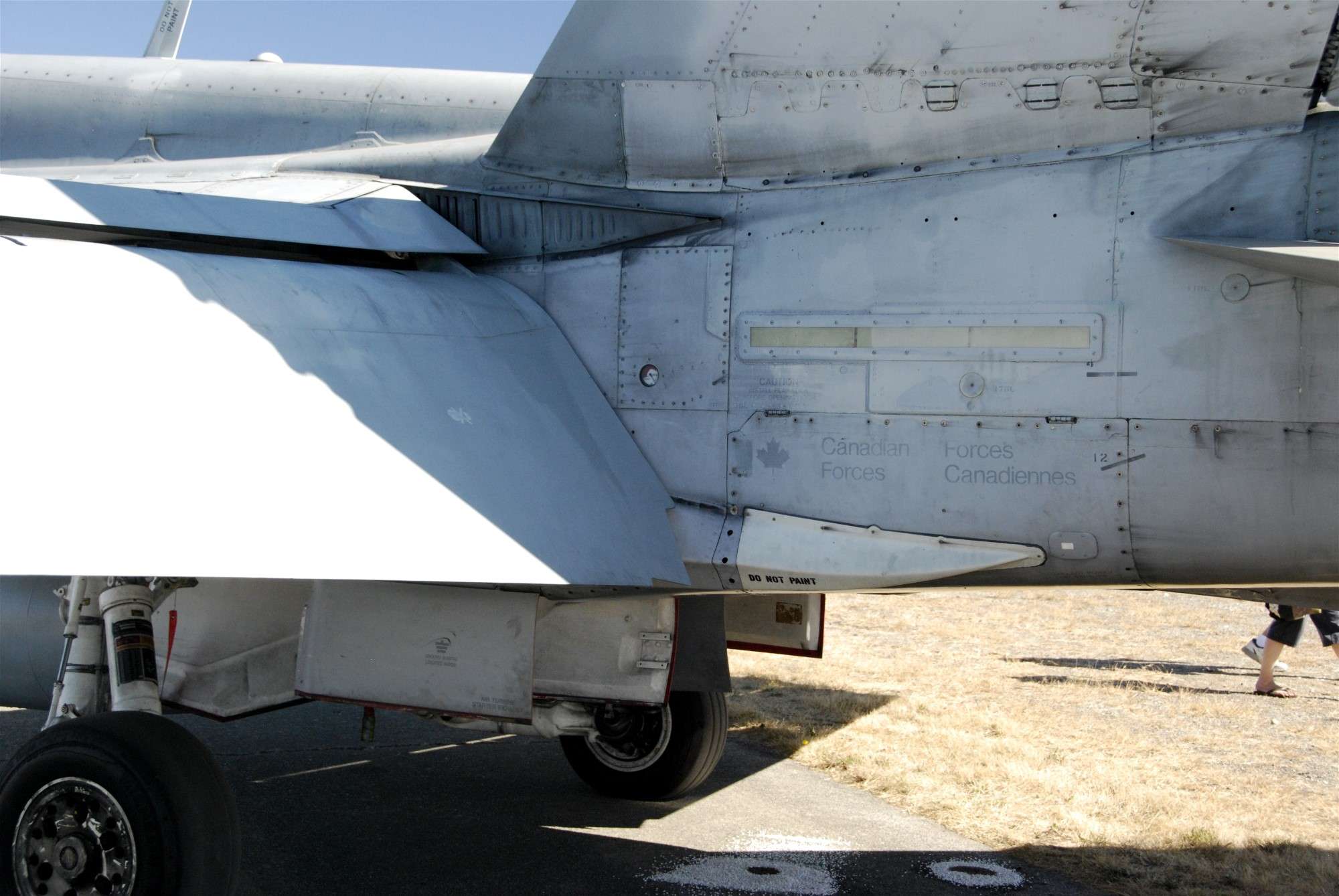
One thing that’s a little surprising to me with F-16’s is that there’s a small gap at the base of the vertical stabilizer, unlike other jets.
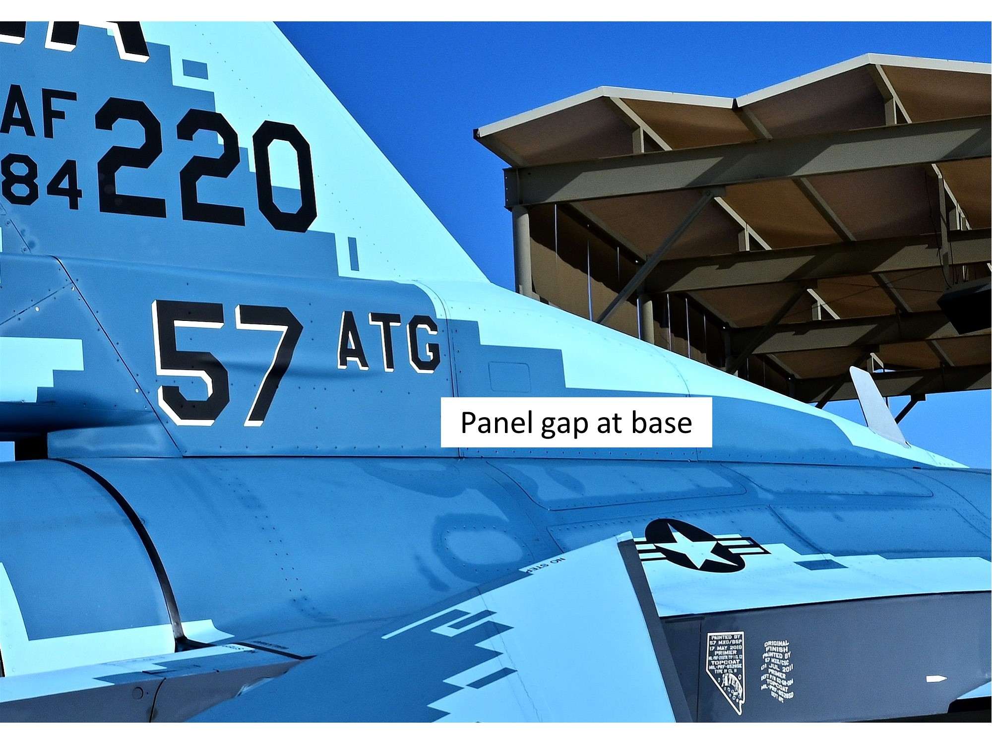
This small gap is perfect for the very tight fitting kit stabilizer, which is friction fit, so you don’t really need to glue it on, so it can be painted and decaled off the fuselage for ease of handling. Note that the small air duct on the base was cut off, which Block 25’s don’t have.
Well that’s it for now, but I thought I would throw out a question that I’ve always wondered about. If F-16’s have 16 static wicks trailing all the control surfaces, why don’t other fighter jets like F-15’s and F-18’s have them as well? Hmmmm…….
Cheers,
Chuck
- SwissFighters, blackbetty, JayW and 22 others
-
24
-
 1
1
-
17 hours ago, Oldbaldguy said:
I’d like to point out that the ‘great teacher’ part comes from Chuck’s unreserved willingness to share with us what he has learned the hard way - by doing something til it works. We all know modelers who would never share some special skill or process because they don’t want anyone else to get glory from it. Chuck is not that guy. Hats off and many thumbs-up. Nice model, too.
Wow, that's a very kind comment sir and I thank you. "By doing something til it works" it pretty accurate for me, because I often try things that don't work at all, like my first attempt at exhaust staining using bits of masking tape, which turned out quite bad. With the pressure from the air brush the tape was pushed against the exhaust, creating a bit of a mess, so it was back to the drawing board with something I knew worked before, which was bits of stiff styrene instead.
I have often seen some of my relatively unique techniques used by others which makes me smile. What's the saying? "Imitation is the sincerest form of flattery" or something like that?
Having said that, I use plenty of techniques in my builds that I learned from others, but I always try to recognize where I got my ideas from if they are special. Marcel's anti-skid walkways using a rough surface Rustoleum in a spray can and Pete's white latex paint dipped F-16 intakes come to mind, but there are many other techniques I can't think of right now. Although I don't use these methods any more, they really helped with some of my past models, so I try to give back to these forums whenever I can.
The Viper Aggressor is coming along very nicely now, with most of the parts now used. I should have an update in a few days once I finalize a few assemblies that needed a tweak here and there.
Cheers,
Chuck
- Zola25, scvrobeson, chaos07 and 5 others
-
8
-
45 minutes ago, Timmy! said:
With enough thrust everything flys. But don’t kid yourself, Pig is running around his basement with the model in his right hand over his shoulder making jet noises.
We ALL do that, so he's in good company.

Great continuing work Pete. You are a Master.
Cheers,
Chuck
-
-
On 4/2/2024 at 9:32 AM, geedubelyer said:
Hi Chuck.
A sister forum to LSP. Plenty of knowledgeable, helpful folks who should be able to help create masks for the "No Push" stencils.
Using stencils would enable you to recreate exactly the look you need.
Fiddly and time consuming but as real as it gets.
Cheers
Thanks Guy! I ordered some decal material that might work for those “No Push” stencils instead. I prefer decals to painting them, because if I don’t like them or screw up, I can just remove them. With paint, I’d have to repaint them all over again and I’m not doing that again!
April 4/24
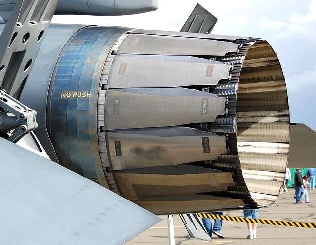
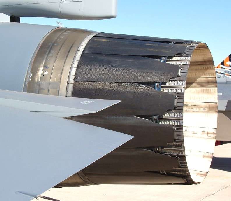
One of the interesting features of these PW100 engines is the color of the shroud around the engine just back of the nozzle, which I’ll just call the engine collar. The Pratt and Whitney collar is quite different than the GE110 collar, which is shallow and always dull titanium grey. The PW100 collar is fairly wide, irregularly shaped, shiny and is often blue, presumably due to heat. I say “often”, because it’s not always blue and the intensity of the blue color is all over the place. After looking at dozens of PW100 collars, here are some examples of what I'm talking about:
Intense Blue and evenly colored, which is fairly rare. I think if I painted my model like this, it would look unrealistic, despite the fact it can be real.
No blue at all. Again, sort of rare, but they exist.
And a few examples of what I think is more common, which is more interesting to my eye. The blue is there, but it’s mottled due to weathering and other factors, like type of engine and maintenance.
Note that some of the bands are not blue.
Blue almost everywhere, but blotchy.
I decided to paint the model engine collar right now for a bunch of reasons:
- Since it’s metallic, I want a super smooth surface with no other paint underneath, like a regular primer or paint from adjacent areas.
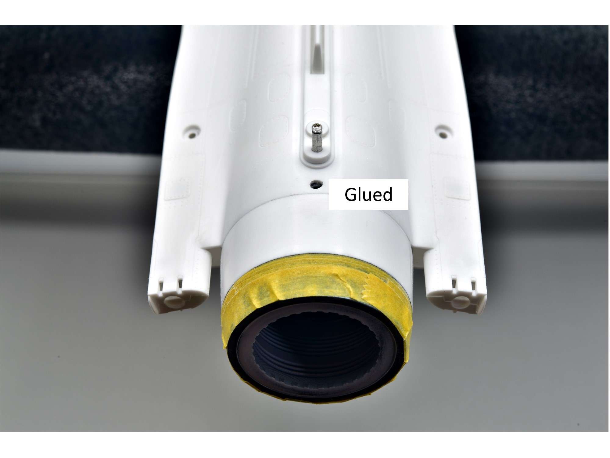
- This collar is situated in an area between the speed brakes that will be difficult to paint later
- I just want to!
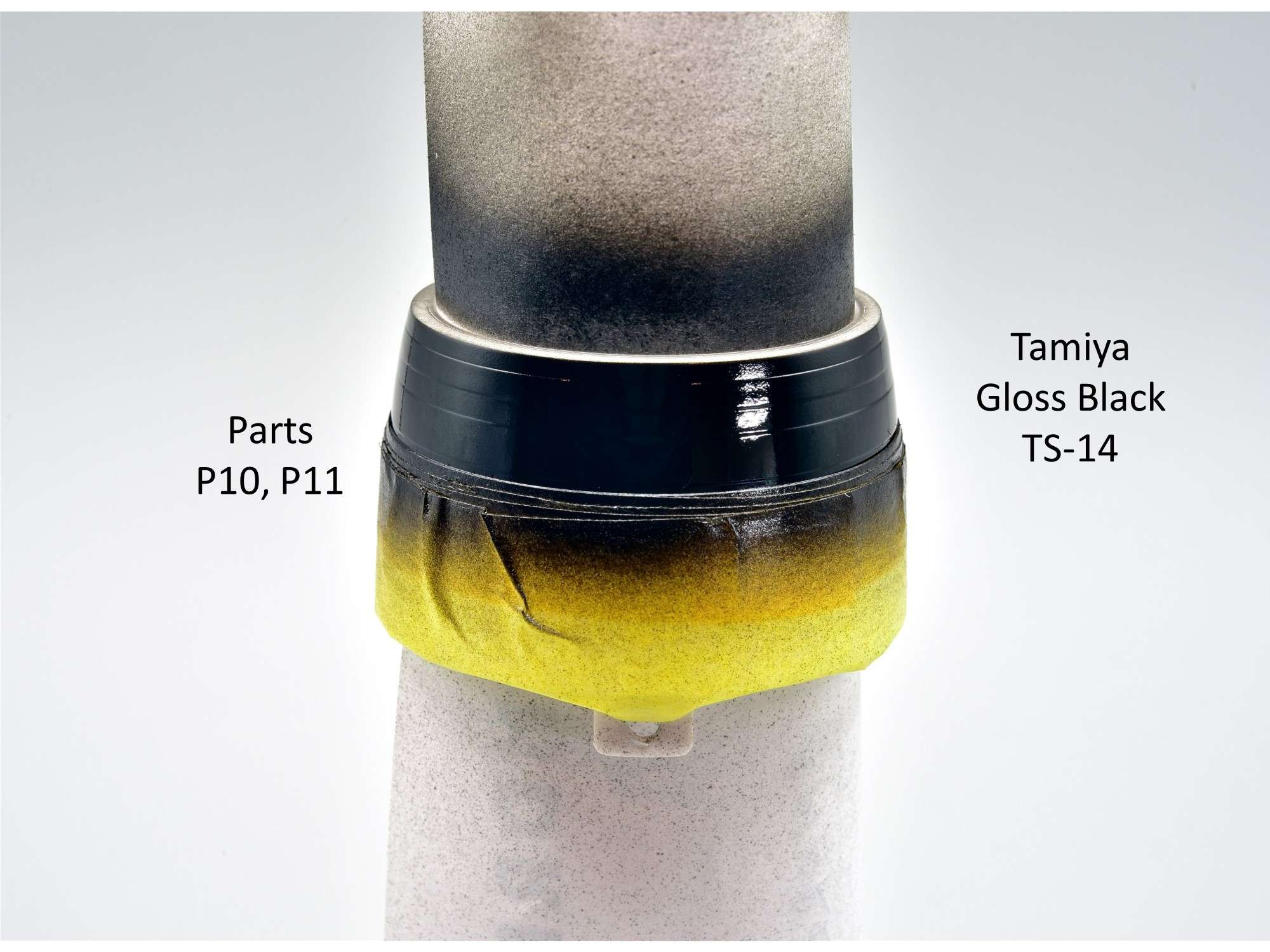
The first step like I always do with Alclad metallic paint, is to start with a primer coat of Tamiya Gloss Black Lacquer from a rattle can decanted into a bottle. I’ve tried the relatively new LP line of Tamiya lacquers in a bottle like LP-1, but I don’t find it as glossy as good 'ol TS-14.
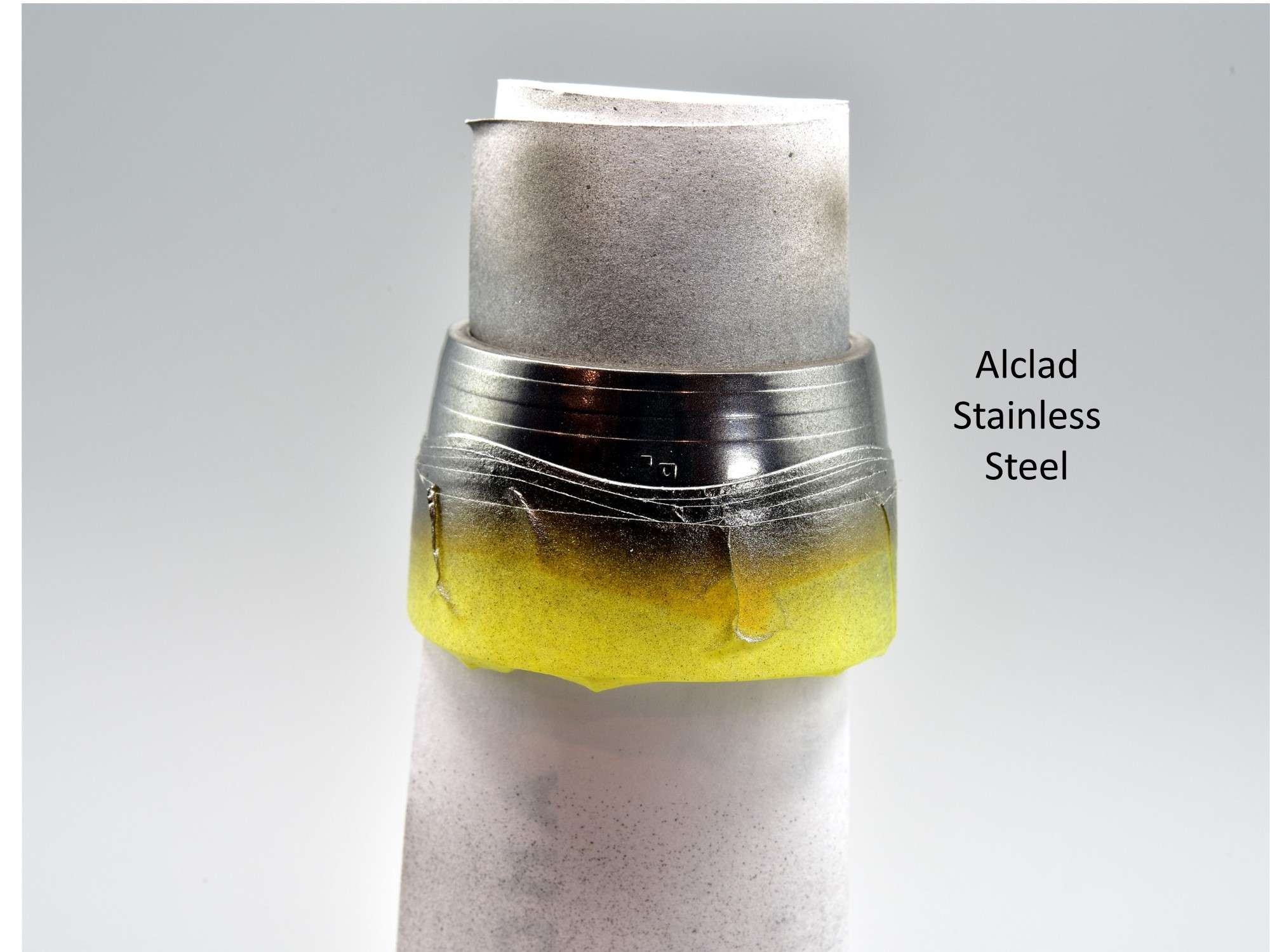
The collar is predominantly a relatively shiny metallic color, so I started with Alclad Stainless Steel. Unlike the “High Shine” Alclad colors like Chrome, this one is tough and can be masked without lifting.
To create a mottled look, I applied liquid mask with a sponge. Salt would work just as well, but it’s messy.
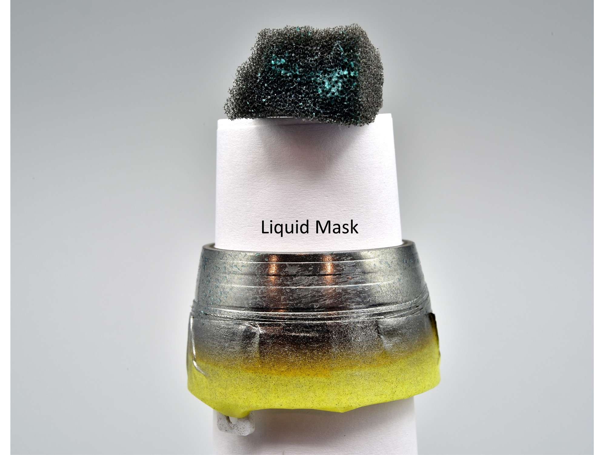
I then sprayed Alclad Hotmetal Blue followed by more liquid mask and Alclad White Aluminum in an iterative sequence of light mist coats. 2 of the rings were masked off so that they would not pick up as much of the blue. Everything was then sealed with clear coat of Tamiya Semi-Gloss lacquer to knock down the shine a bit.
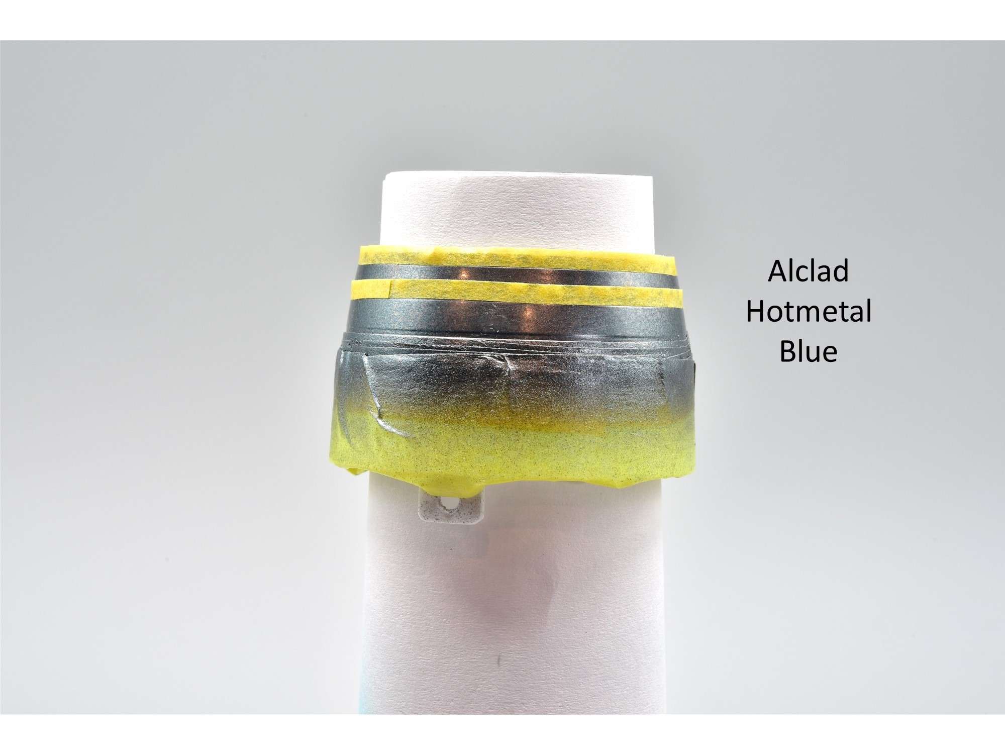
The results. This is tough to photograph to see the real colors and relative shine.
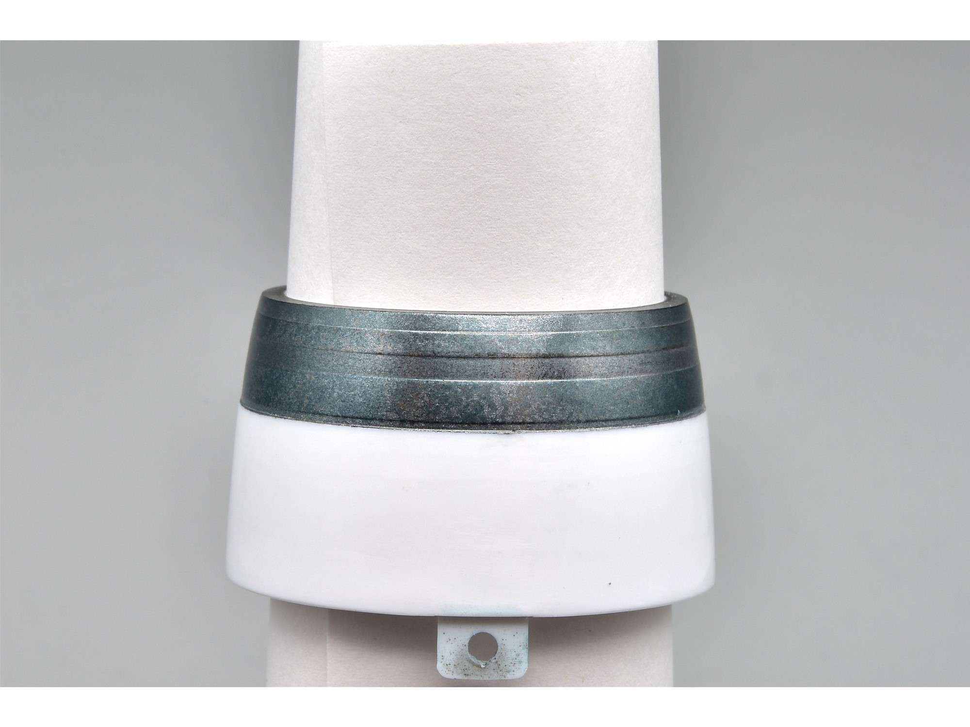
Parked on the model fuselage with the nozzle attached, it starts to look more natural and you can see that it's much shinier than the exhaust, as it should be. I used a screw at the top through the alignment holes to hold things in place, since this assembly isn’t glued in yet.
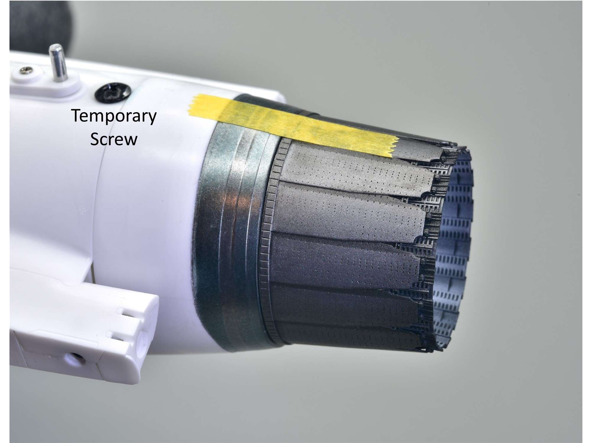
The small gap between nozzle and collar will be much tighter with glue.
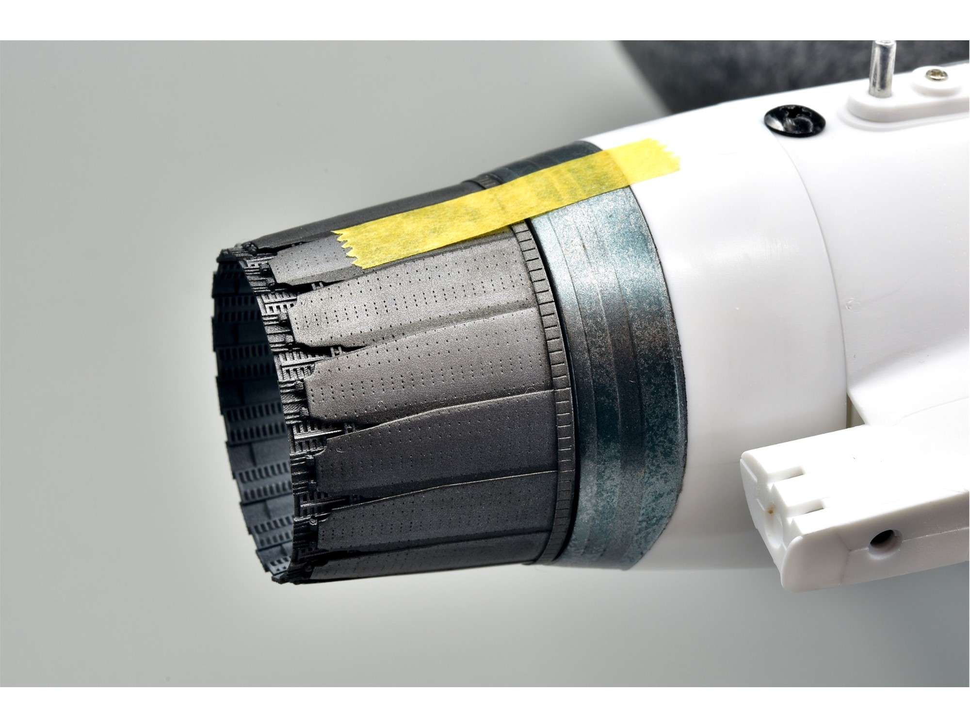
Of course I had to show off the exhaust staining again.
I’m pretty happy with how things turned out, because now I have the “blue look” of the collar, without it looking too pristine and unrealistic.
With the engine collar now painted and sealed, I can then mask it off and assemble the entire engine as described earlier.
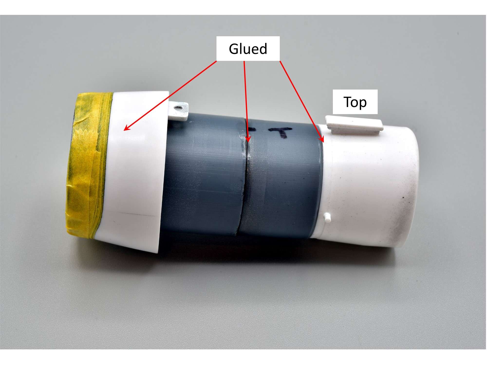
It now just slides into place
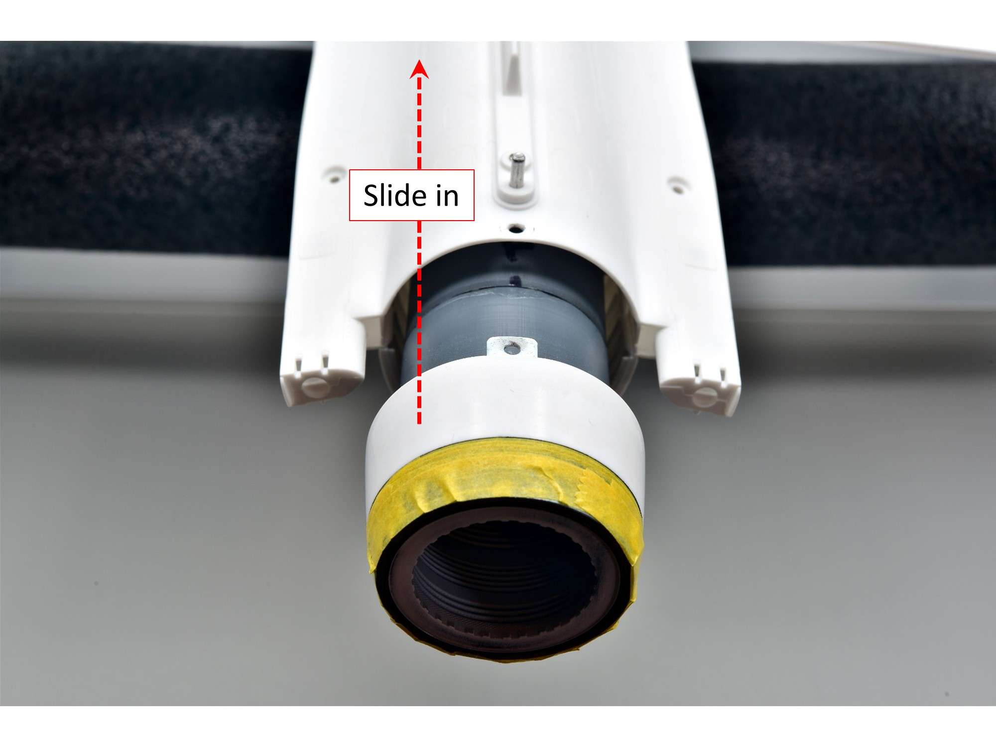
And is now securely glued to the fuselage.
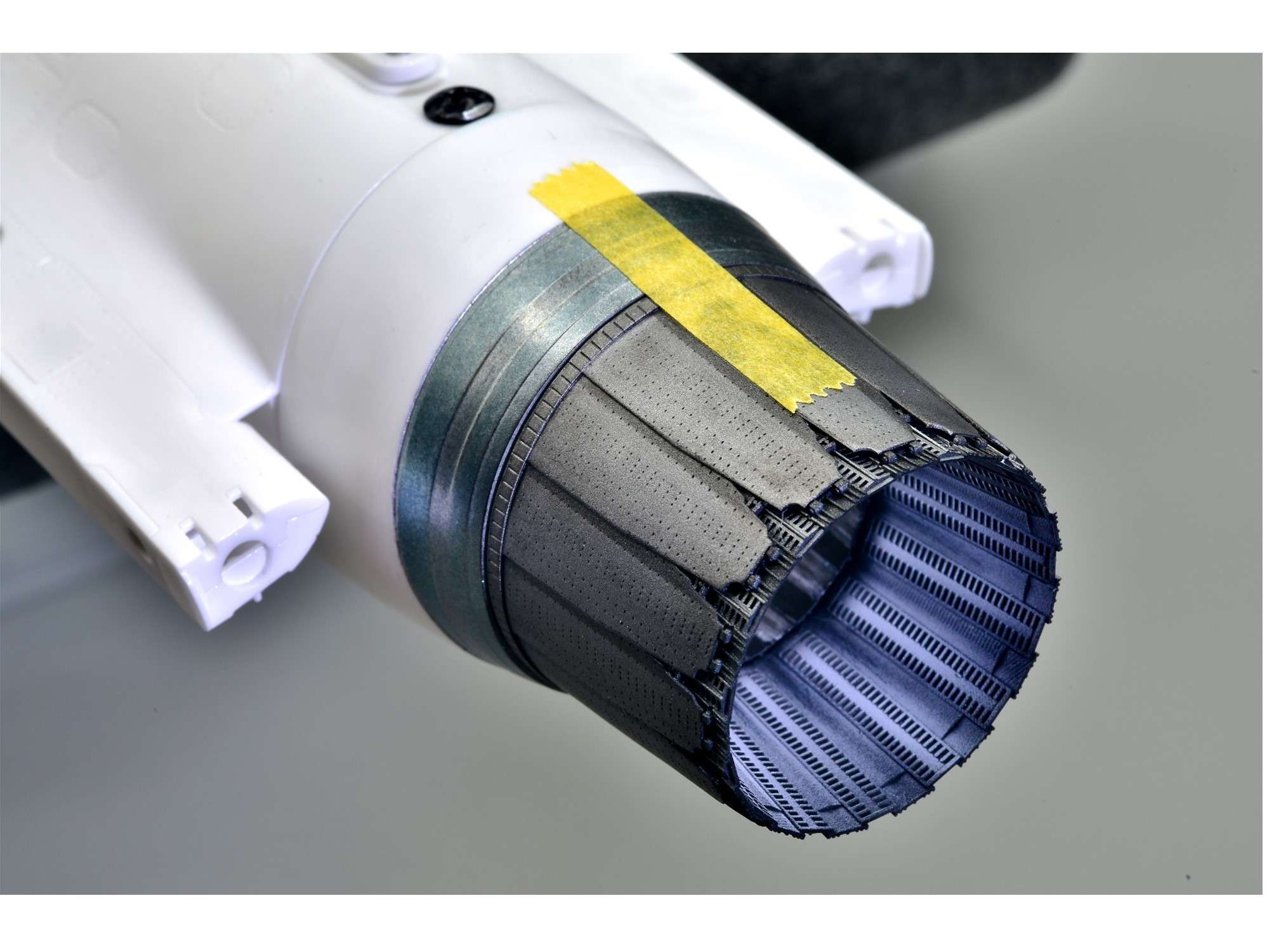
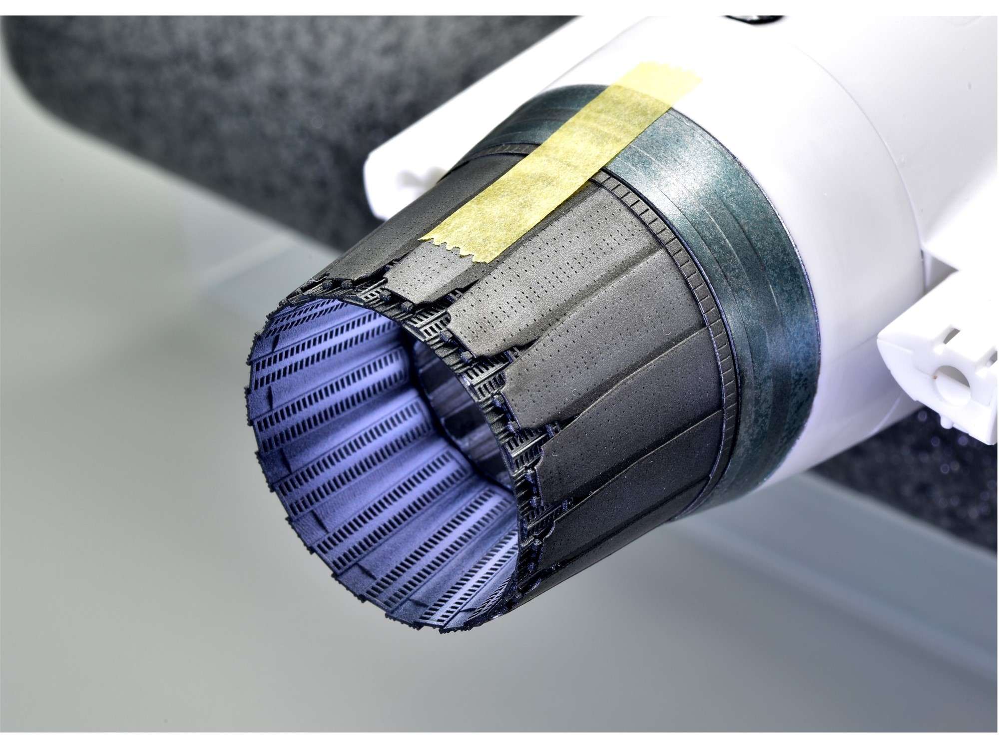
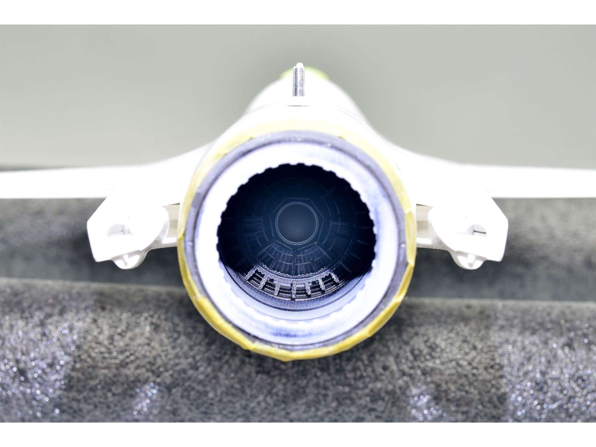
Last peek at the afterburner face before I fill this engine cavity with foam and mask it off.
That’s it for now and thanks for your continued interest and “like” responses, which I appreciate very much.
Cheers,
Chuck
- LSP_Kevin, Piero, TankBuster and 23 others
-
26
-
-
Thanks Everyone! Much appreciated.
6 hours ago, airscale said:just exquisite work Chuck - when I grow up, I want to be able to paint like you
")
..those F15 cans are Biblical..
Peter
Thanks Peter. Here's one more pic of them to see the exhaust staining better from the rear. The staining turned out a bit better than my current exhaust, but after 3 attempts, I'm done!

Similar angle and lighting...
Cheers,
Chuck
-
March 31, 2024
Painting of the engine is done, but it was a real struggle because I’m so picky. Painting a jet engine, inside and out, is challenging because of all the metallic and ceramic colors and no two engines are the same- but there are some similarities that you try to replicate. It’s also very artistic, which can be both fun and frustrating. I want all of my engines to add to the model, rather than be a liability where “good enough” is never really good enough.
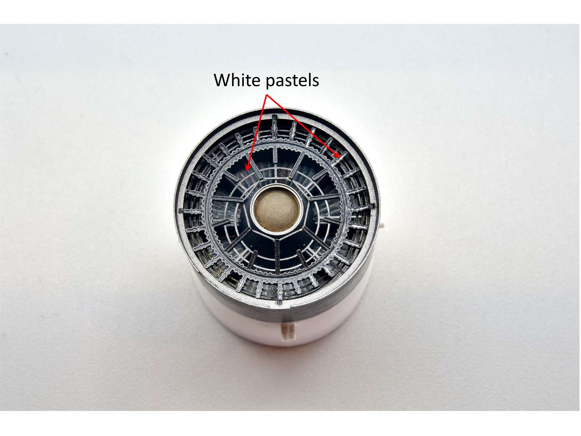
Starting with the base (front) of the engine, I painting everything as close to what I could find for reference pics. This is a combination of dull metal and a whitish ceramic look, which I enhanced with white pastels. It’s a bit of a shame that you won’t see much of this later, when it’s buried deep inside the fuselage.
The flame tube was painted black at first, then I shot flat white paint through it from front to back, using a crude zig-zag mask that created irregular dark shadows within.
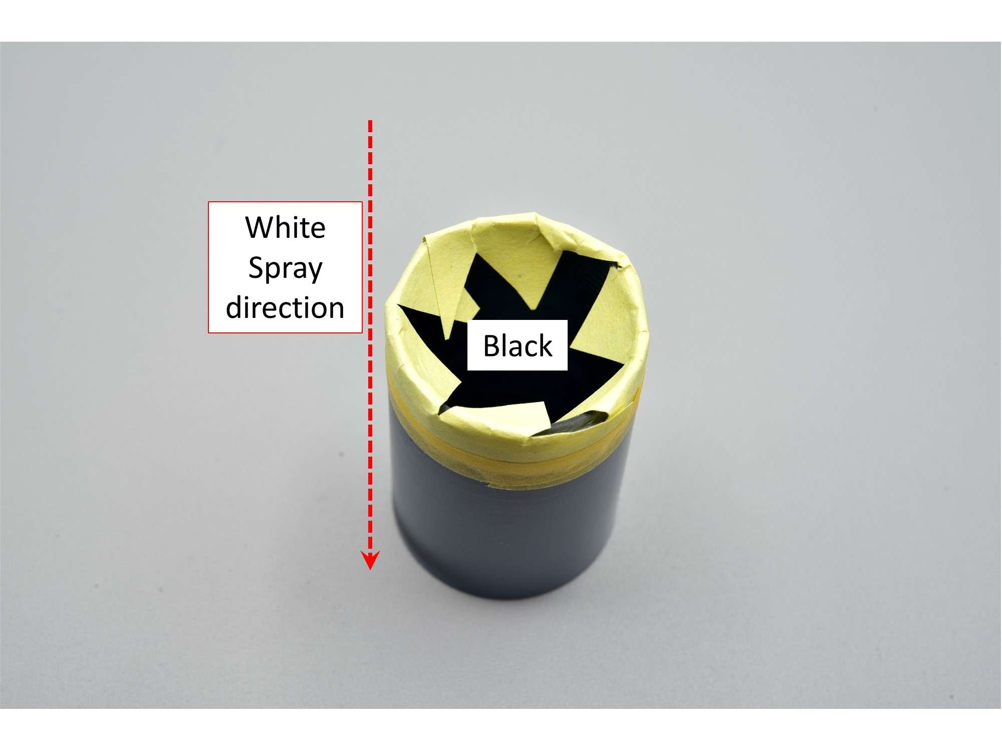
Painting the outside petals of the nozzle was the hardest part, because I wasn’t happy with my first two attempts and had to strip everything down and start all over again. With 3 small pieces of masking tape and 15 petals, that’s 45 bits of tape that had to be applied 3 times! As I’ve done before, I used an ordinary piece of paper rolled into a tube to hold the nozzle for painting. Not only does it hold the nozzle, but it also shows where you painted and where you haven't against the white background.
I looked at countless Pratt and Whitney F-16 engine nozzles as a reference and used this one the most. Note that the petals have 1 straight edge where the petals overlap, rather than 2 curved ones, which appears to be more common. This Reskit nozzle seems to be the same.
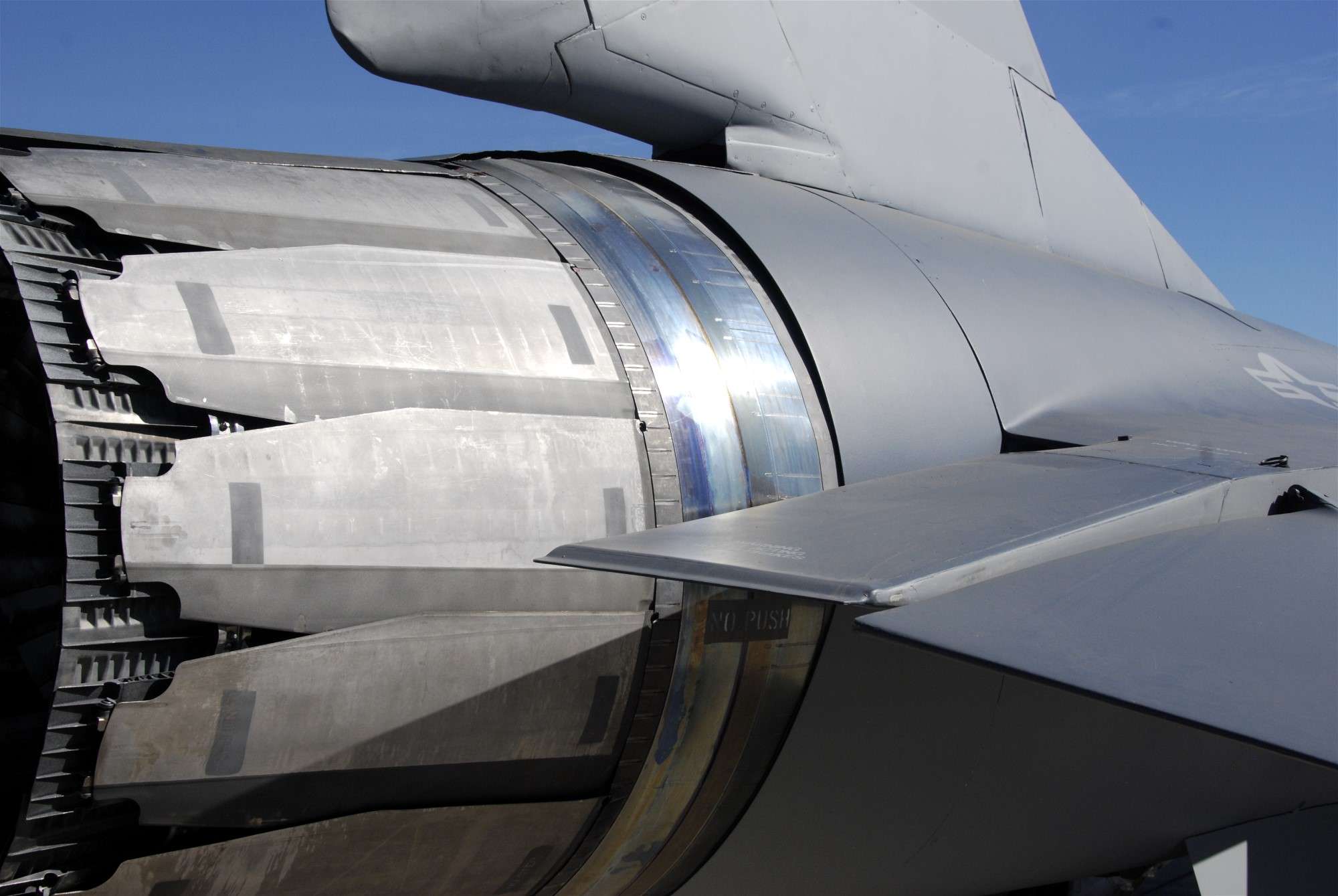
A more common pattern of a curve on both edges of the petals.
The end result, after finally settling on Alclad Durluminum for the main petal color and Alclad Magnesium for the overlap. I tried a lot of other colors but these two seemed to be the closest to the real deal. If you look at the nozzles above, they are fairly smooth as Pete pointed out and all that tiny rivet detail is not very obvious. Instead of filling it all in, I opted to just live with it, because doing so would likely harm the other fine detail that I want to keep.
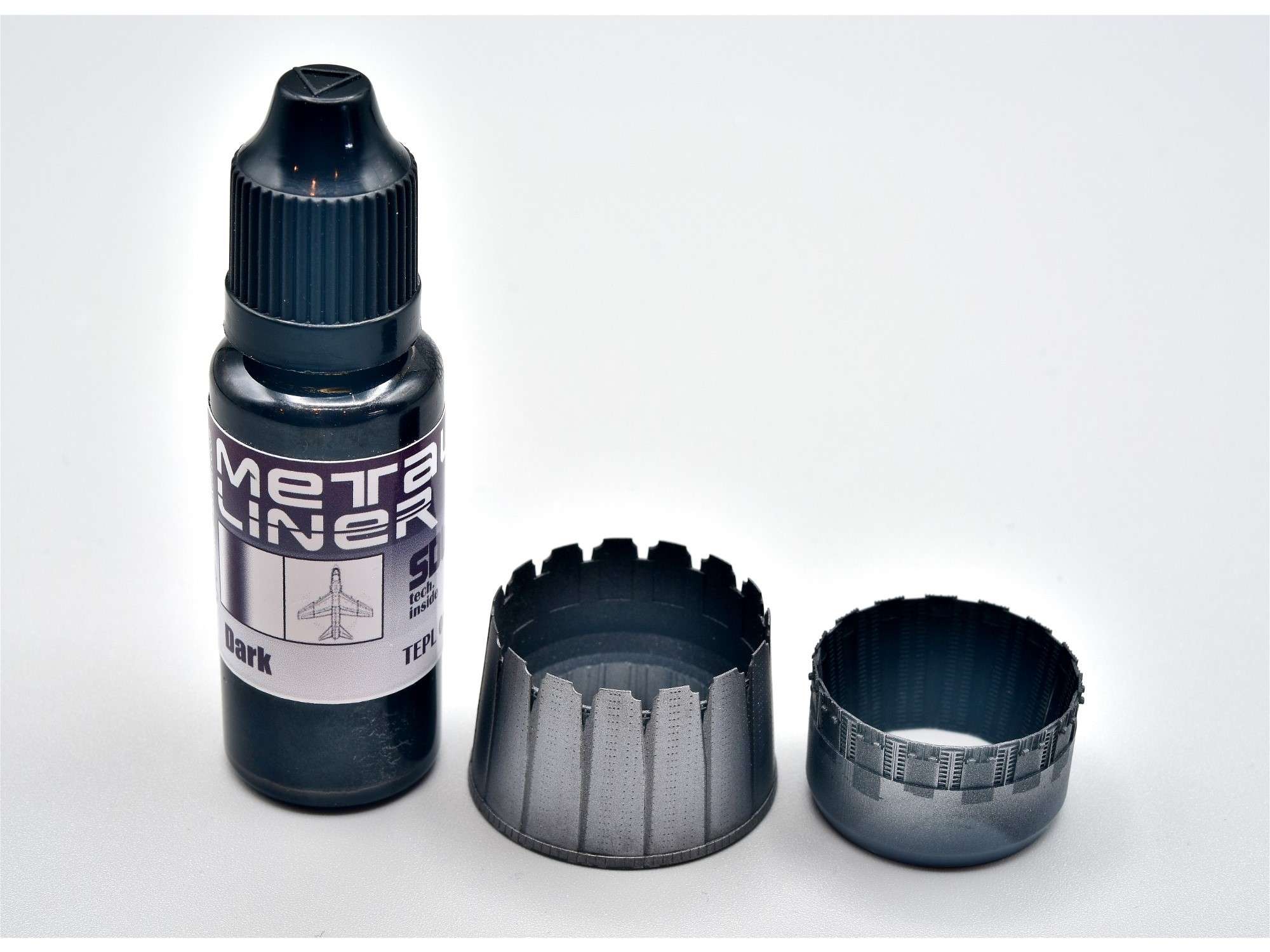
Note that the nozzles are not spotless and there is some wear and discoloration here and there. As I did with my CF-104 build, I decided to use some “Metal Liner” wash to dirty them up a bit.
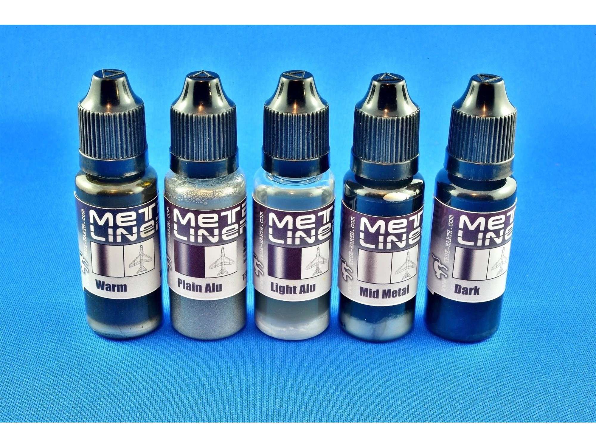
I went with “Dark”, because the lighter washes didn’t really show up on the light surface.
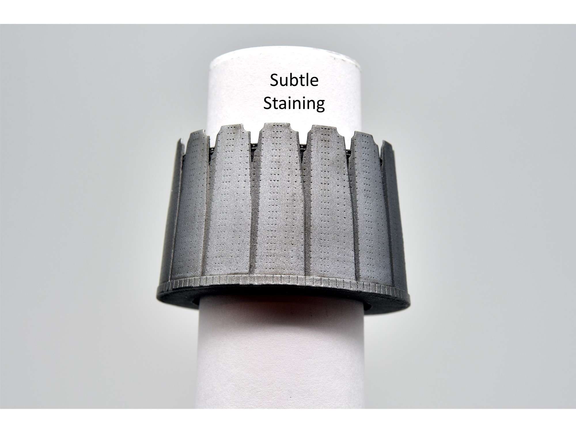
I decided to go light on the wash to give the nozzles some stain, but not too much to overpower the metallic look, especially for small 1/32 scale.
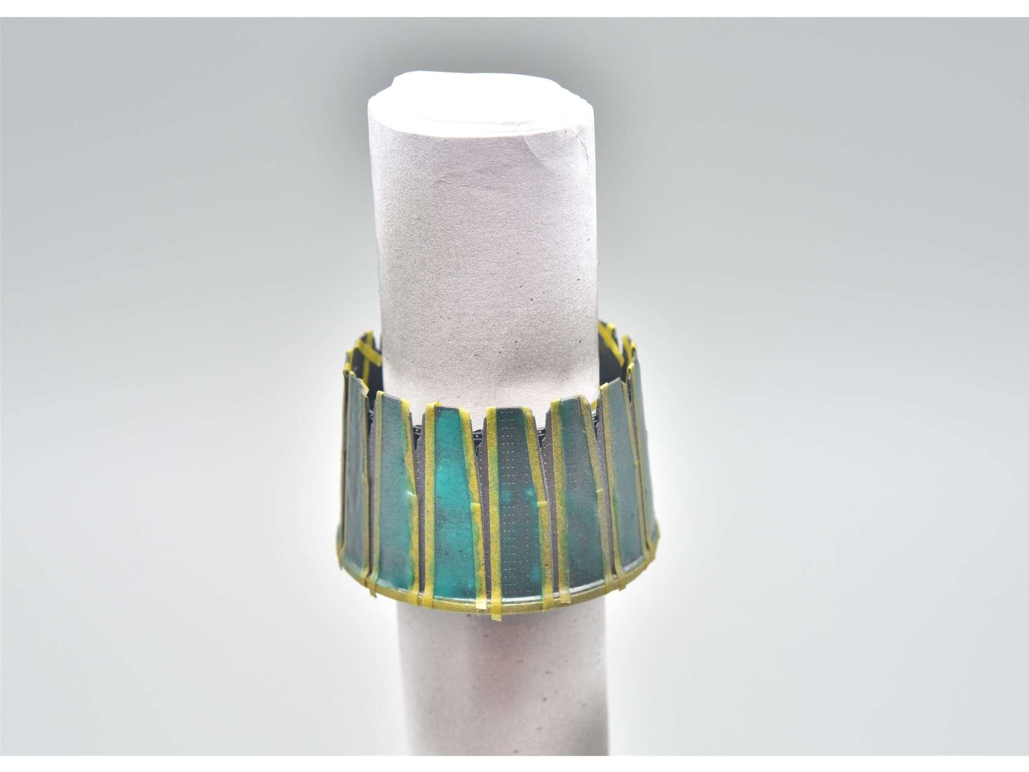
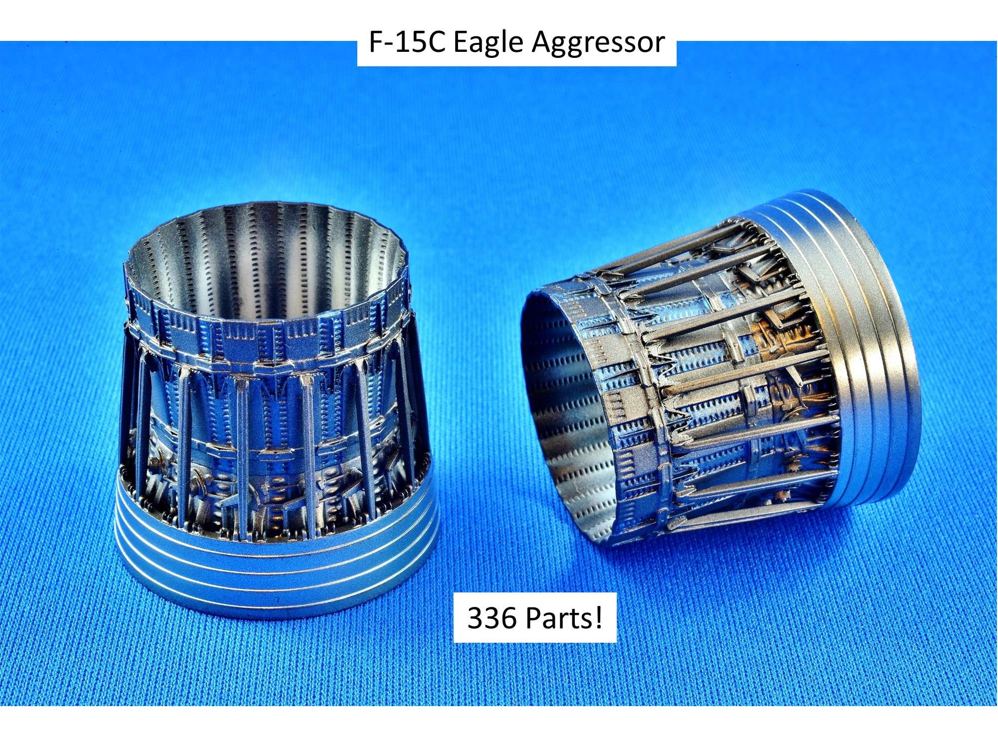
Painting the insides of the nozzles was also a struggle, because I tried a few new ideas and they all crashed and burned. What you want is a combination of black and white soot that has a fairly distinctive repetitive pattern, depending on which part of the nozzle petal it’s on. Make some mistakes, like I did, and you get a combination of white and black in a grey mess, so I had to start all over again and go with something that I know works quite well on these PW100 engines. Here’s a pic of what I used on the engines of my F-15C Eagle Aggressor 6 years ago. Small thin strips of styrene, taped to the base of the nozzle along an axis that usually has less white soot than on either side, provide a partial mask when flat white paint is sprayed from the base of the nozzle outward, just like on a real engine.
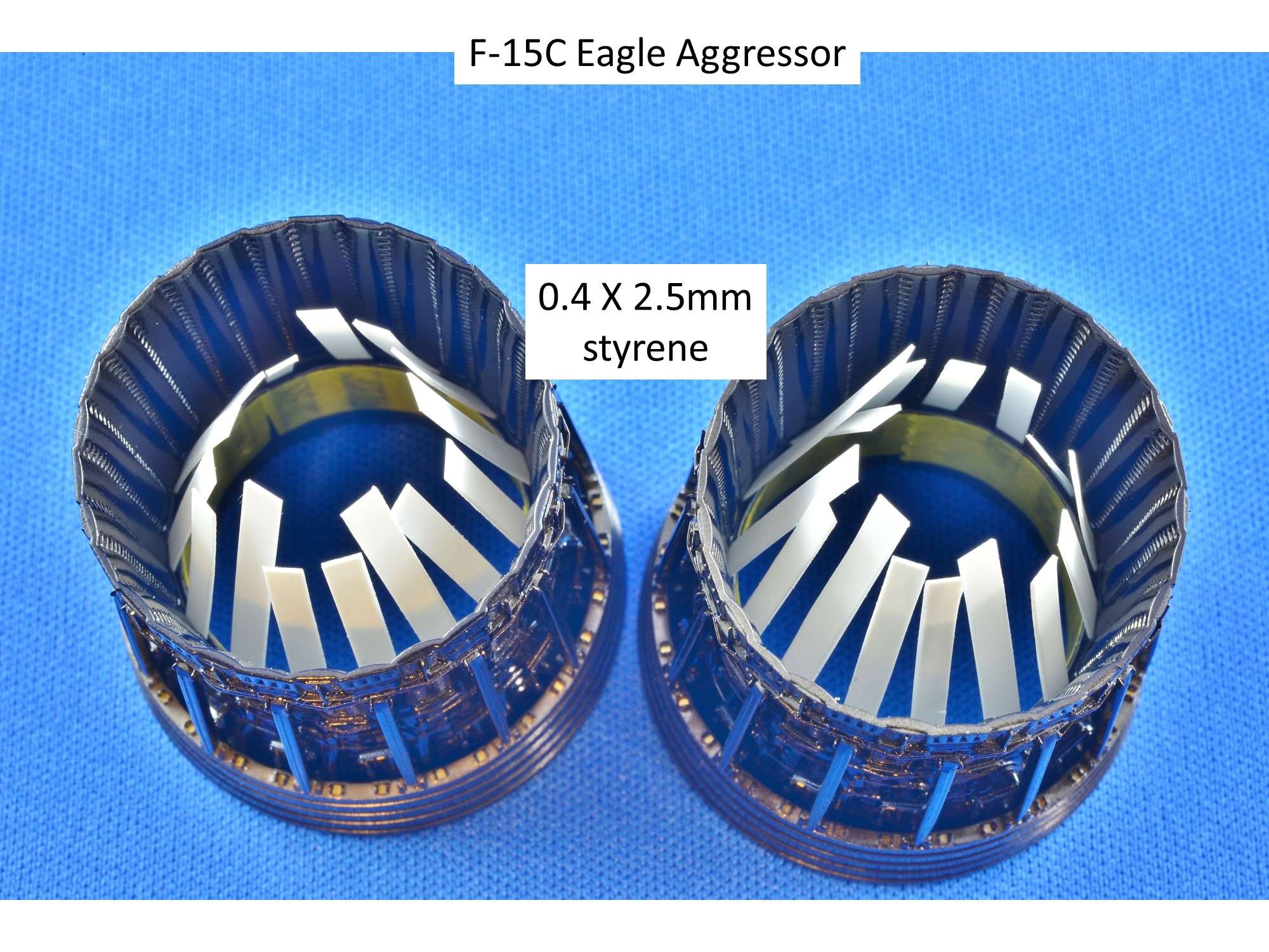
The results can be pretty impressive, as shown on this pic I’ve shown at least 100 times here before, because I’m so proud of these nozzles. Long before ResKit and others created fantastic looking nozzles using 3D printing technology, I made these out of a resin Two Mikes base and 11 Eduard and kit parts per petal. 30 petals combined with the 6 main parts of the nozzles equal 336 parts! They took me forever to assemble, but I think they were worth it.
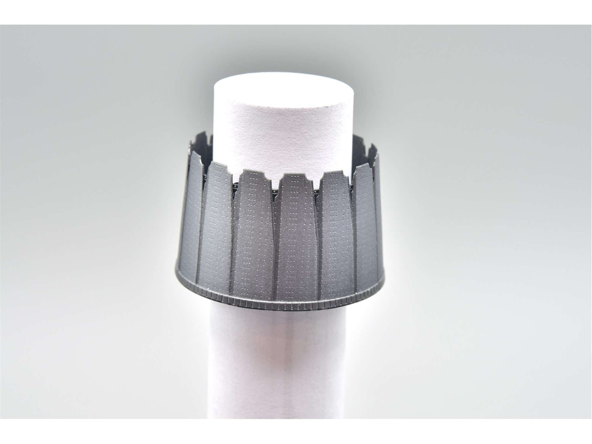
So I did the same thing again, using 0.4 X 2.5MM styrene strips, which fit each petal axis perfectly, they sprayed flat white paint from the rear outward.
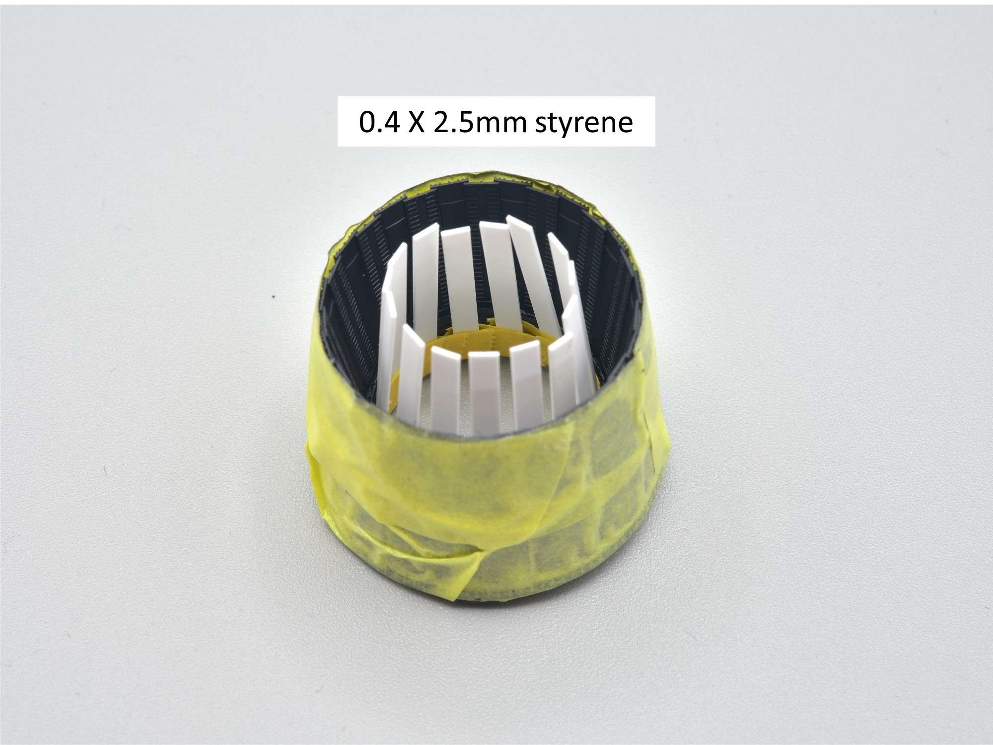
The results, and this time I was very happy with the ending.
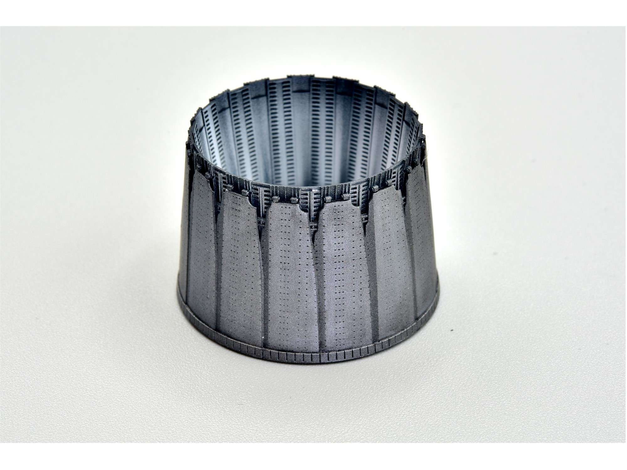
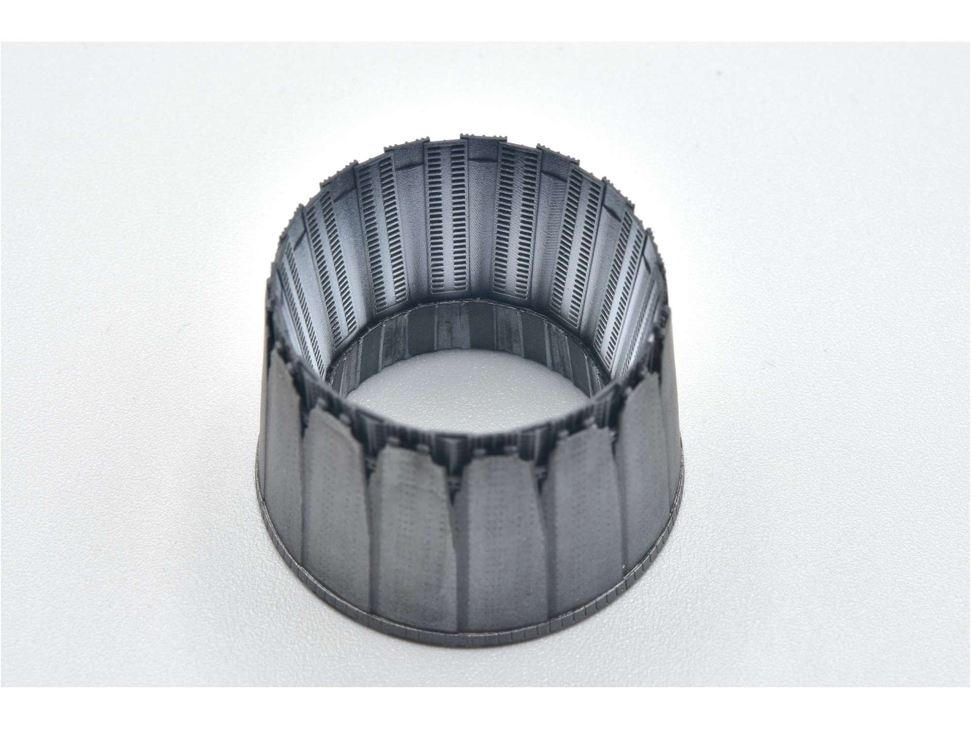
Added to the flame tube. If you squint you might be able to see the dark shadow I created in the tube with that paper mask.
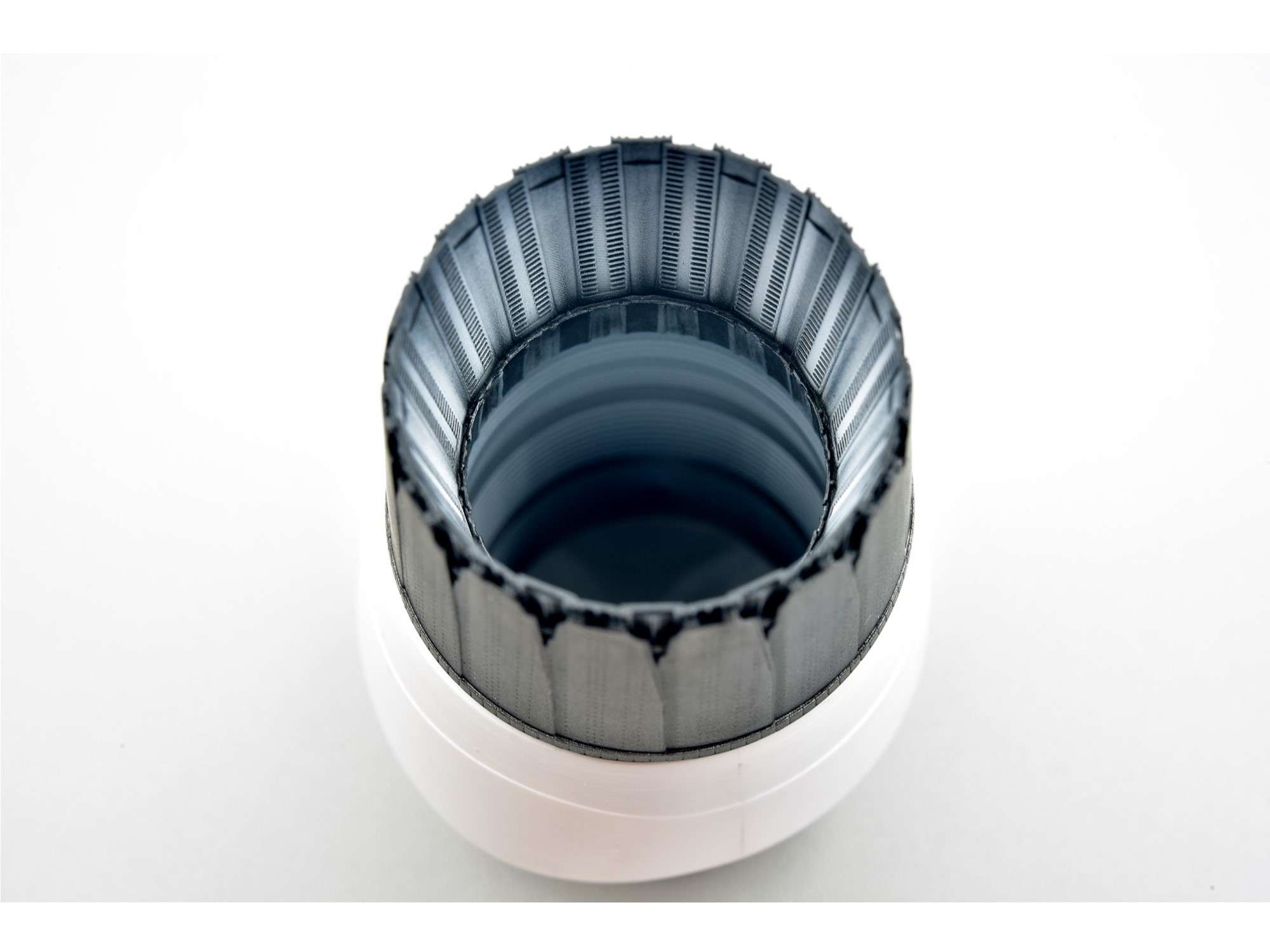
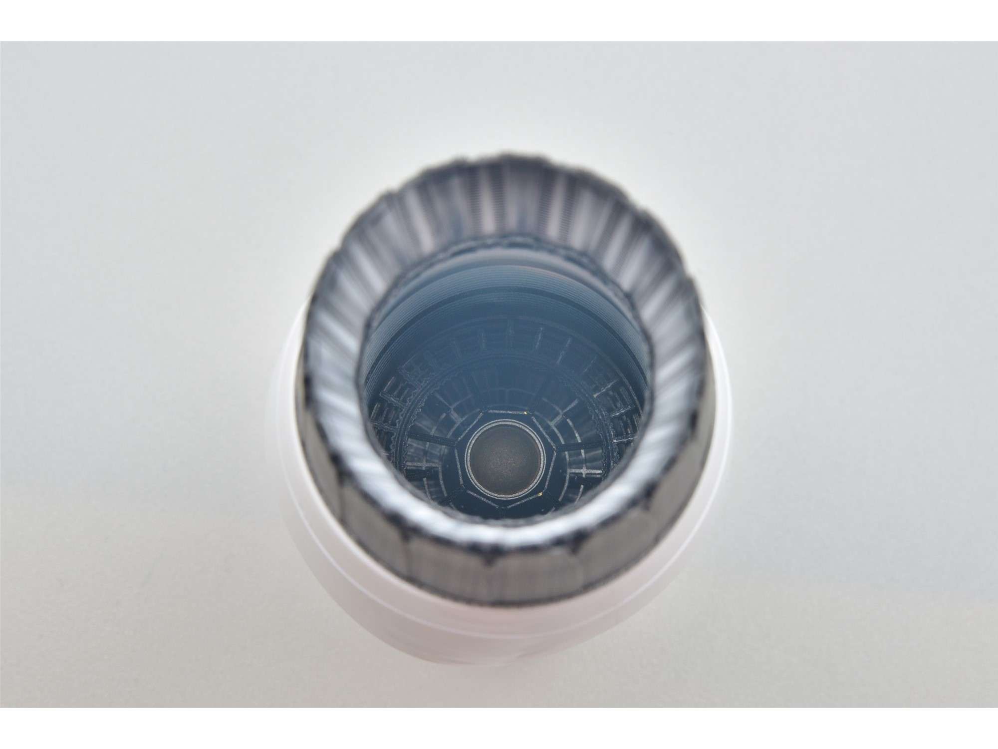
All engine parts combined so that you can barely see the front of the engine face. This is really hard to photograph without a special macro-flash.
Engine painting done! Now I’m scratching my head wondering if I’m going to add all those tiny “No Push” and “No Step” placards to the petals and how the heck I’m going to do it? Maybe tiny strips of decal film? Stay tuned……
Cheers,
Chuck
- Fanes, Memphis, Paul in Napier and 22 others
-
25
-
Thanks Guys!
17 hours ago, Pete Fleischmann said:Looking great Chuck!
I really like the Reskit nozzle- my only beef with it are the rivets on the individual petals. I just don’t see them in my memories of actually touching the jet during preflight; and they don’t show up in any reference photos that I’ve found. Me? I’d fill them..but your mileage may vary..
cheers
Pete
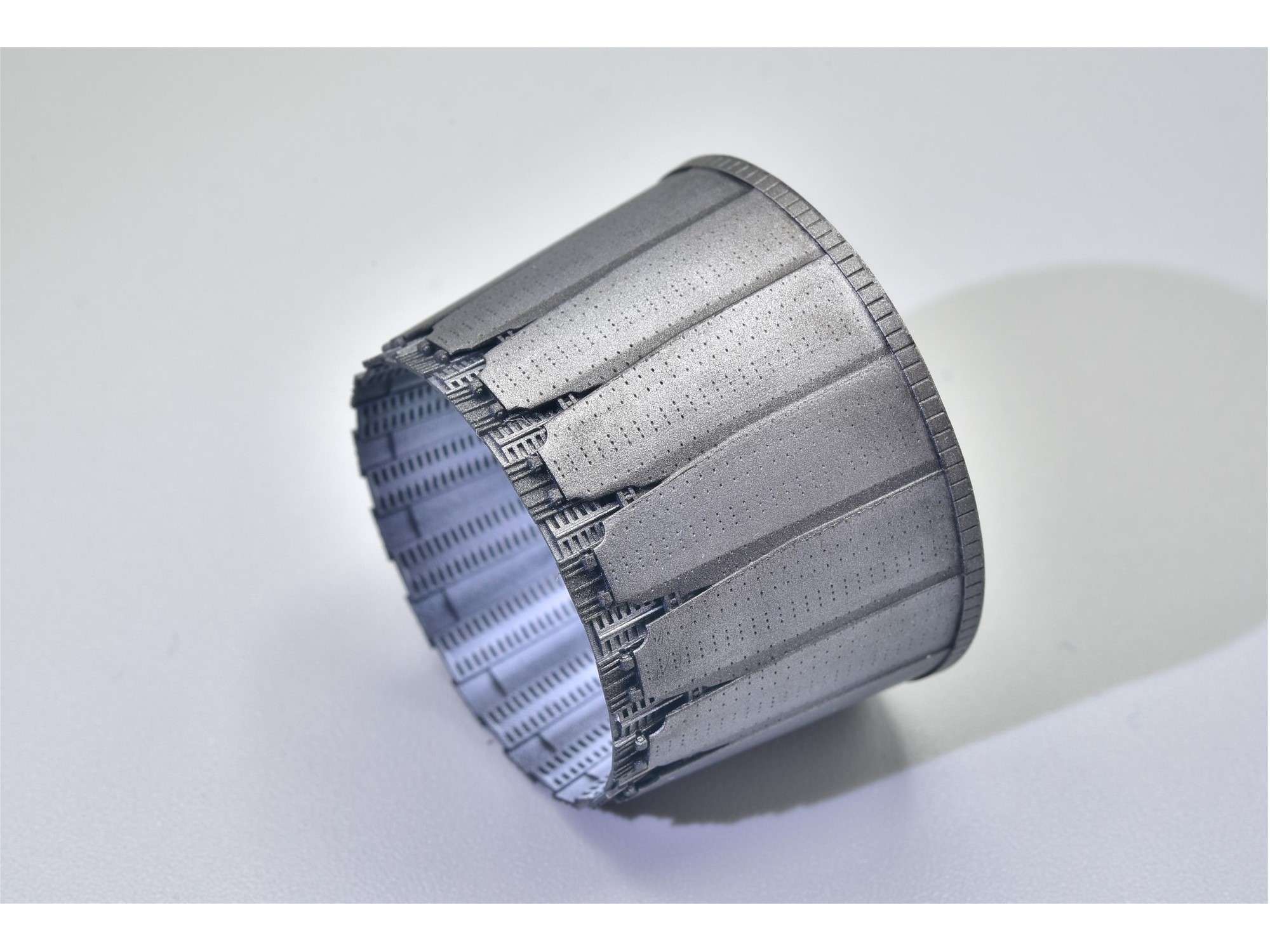
Thanks Pete. Funny, I was just researching this very topic this morning, since I'm now painting the engine parts. Here's the ResKit nozzle once more for reference, with lots of tiny rivet detail.
What I found in my own pics of these nozzles and on the 'net was all over the map, but it's clear that 90+% of the PW100 petals are smooth as you point out with no super obvious rivet marks like this one. The nozzle collar isn't always blue either, but since I think it looks cool, I'll be adding some Alclad Hotmetal Blue to mine.
The next thing I thought, was that maybe ResKit was trying to match the newer 229 engine, which has a distinctive carbon fiber look which is almost black. The little dimples are super tiny and random, however, so it can't be that.
Digging around, I found a fairly rare pic of exhaust petals that are near new, which show the rivets fairly well. Those "No Push" placards are usually cooked on and you can barely read them like the first pic above.
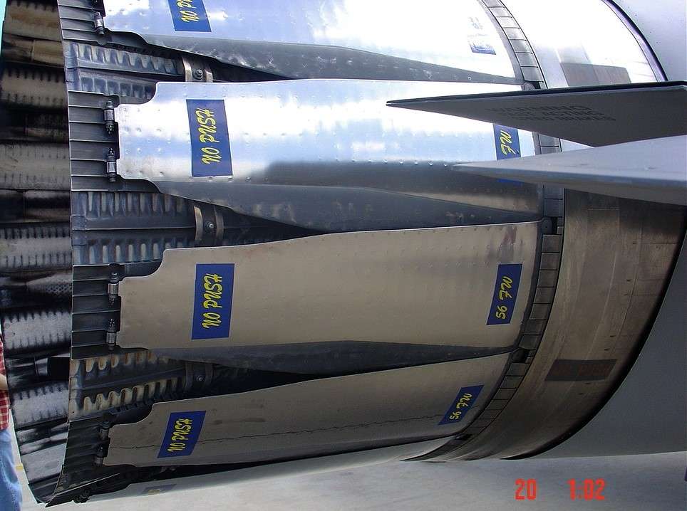
Over time, heat and weathering, this is the look that's more natural.
I don't see me filling the rivets in, because the detail is so fine, doing so will likely create a bit of a mess of the delicate blade boundaries. I think, however, that I have a few ways of toning them down, at least at a bit of a distance. Time will tell if I'm successful- or not!
Cheers,
Chuck
-
You are a modeling (manufacturing) machine Peter! Great subject.
If it is of any assistance, we have Hawker Sea Fury here in a Calgary military museum that I could take reference pics of. It used to sit outside for years which made me cry, but it has since been cleaned up and brought inside for at least 10 years. While it's roped off and I can't climb all over it and take pics of the cockpit, I can certainly take pics of just about anything on the outside. According to what little I can glean from the 'net, its FB11, WG565 if that makes any sense to you. Just send me a PM if you're interested.
Cheers,
Chuck
- airscale and Alain Gadbois
-
2
-
March 27, 2024
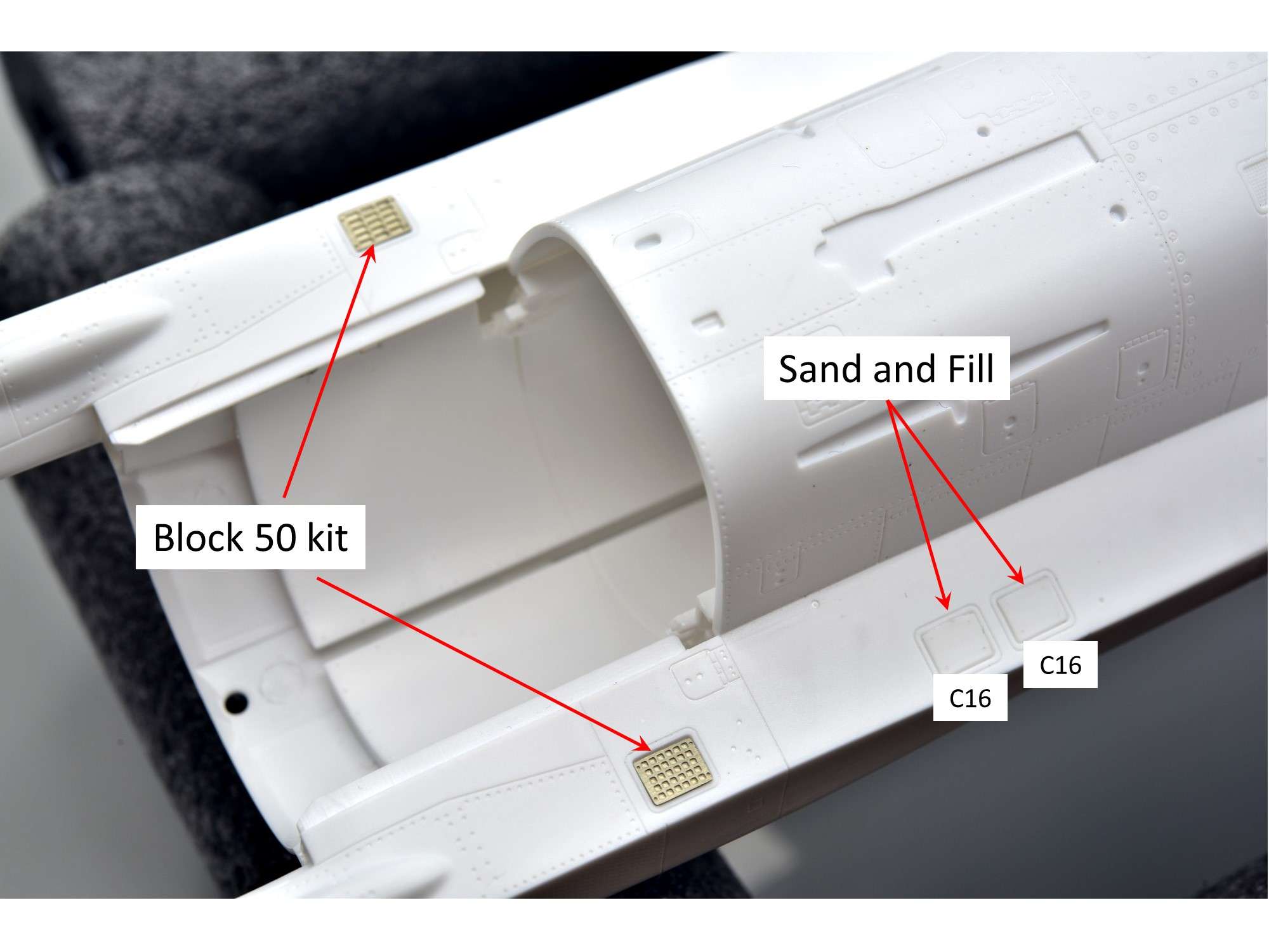
Since I’m now trying to make sure my model is as accurate as possible for a Block 25 in every way possible, I found another change I need to make since this Thunderbirds kit is for a Block 32. Apparently Block 25’s only have 2 flare/chaff dispensers on either side at the rear, and don’t have the extra 2 added on the left hand side as shown below. Eliminating them was easy by gluing in the cover Part C16 plates, then filling the recesses with CA glue and sanding everything smooth. For the 2 dispensers at the back, however, this kit doesn’t have any since the Thunderbirds have cover plates on them. Thankfully I have a few spares from the Block 50 kit, which has 8 of them.
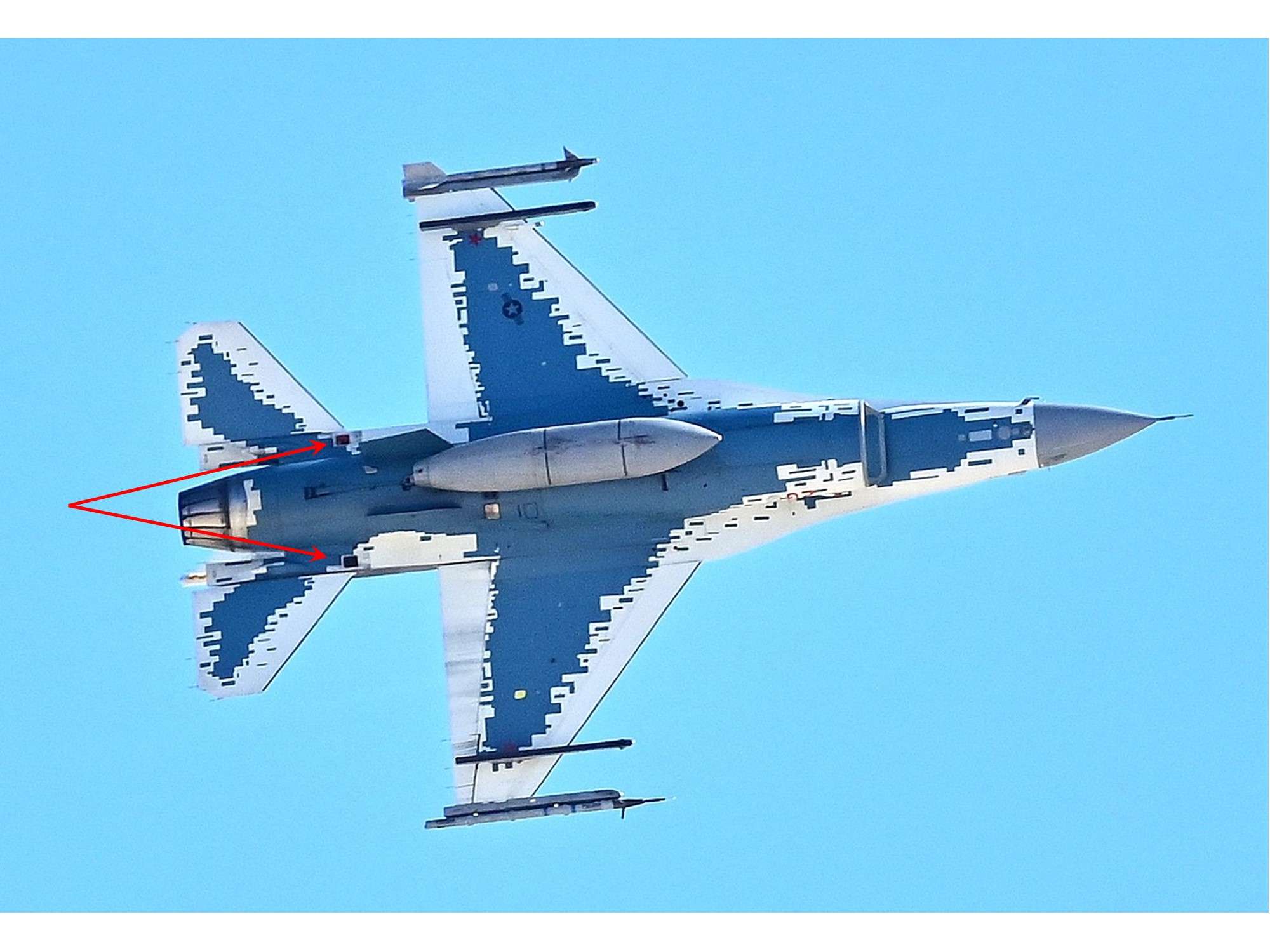
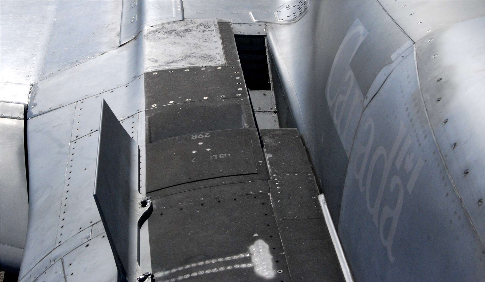
This is confirmed by a pic I took of my subject in November 2022 at Nellis AFB. Note that the forward 2 dispensers are missing as they should be for a Block 25.
Next, I decided to get into the ResKit F100 PW engine I bought for this build, but it doesn’t indicate if it’s the original 200 version, or the more modern 220 or 220E version. No matter, because this is the one I’m stuck with.
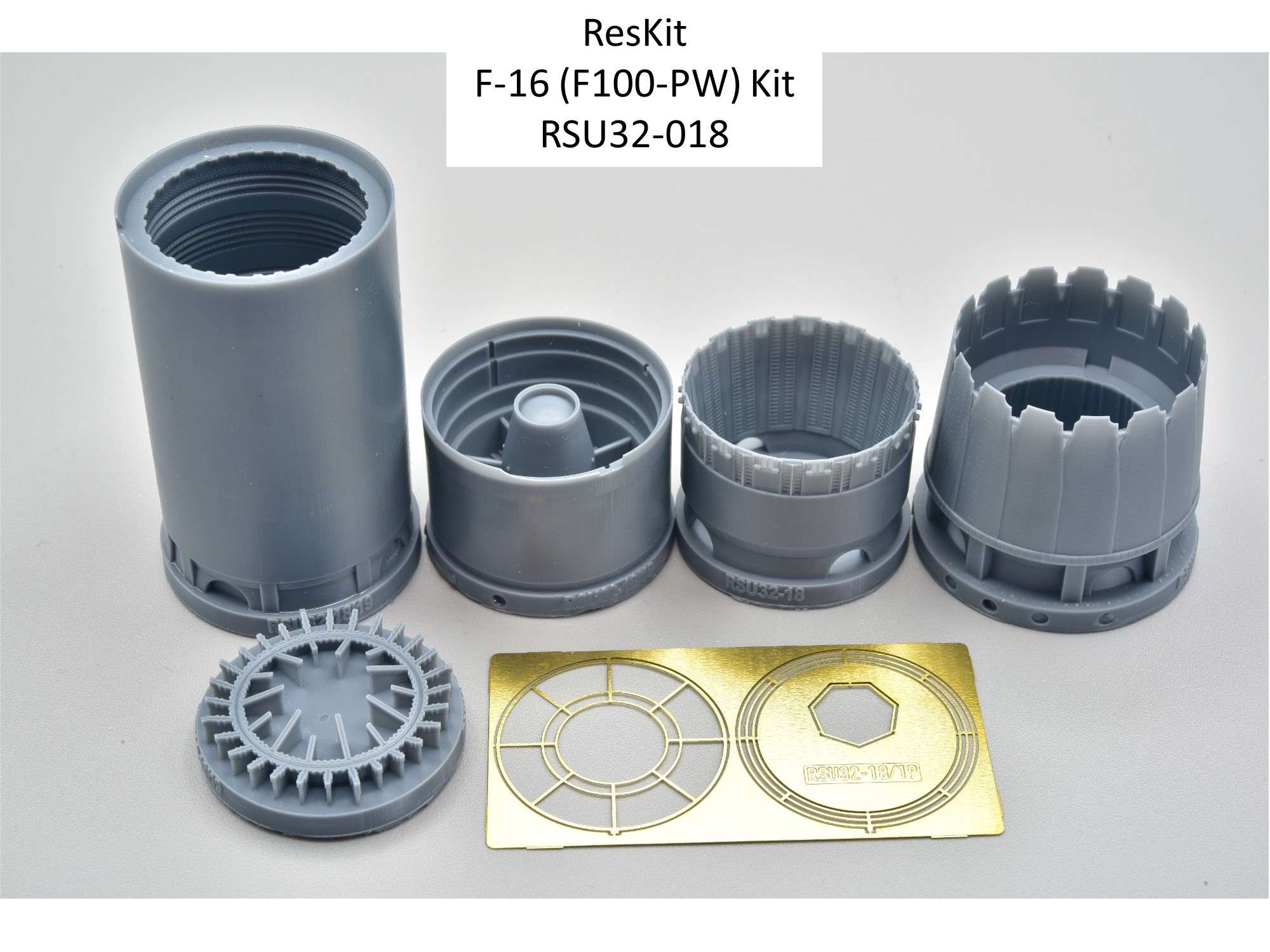
This engine is super detailed like the ResKit J-79 engine I used on my CF-104 build, that turned out looking pretty good if I do say so myself…..
Like the J-79 engine, unfortunately, the instructions just show you how to put the engine together, with absolutely no guide as to how it should fit with the kit parts. You are left to figure that out on your own, so I came up with a plan as you will see below.
Like all ResKit resin, there are large casting blocks to cut off with a razor saw, which is tricky to do without damaging the fine details of the delicate parts. Here is the main nozzle part and the approximate location of the cut line on the instructions.
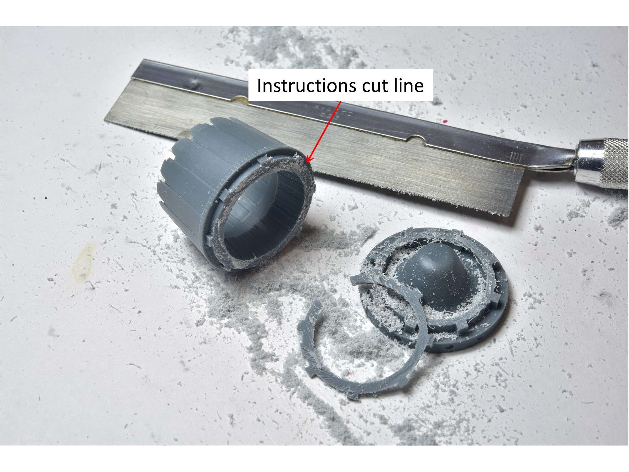
The best way to smooth out the cut line is to rub it on a rough sponge sanding block to get off the biggest chunks.
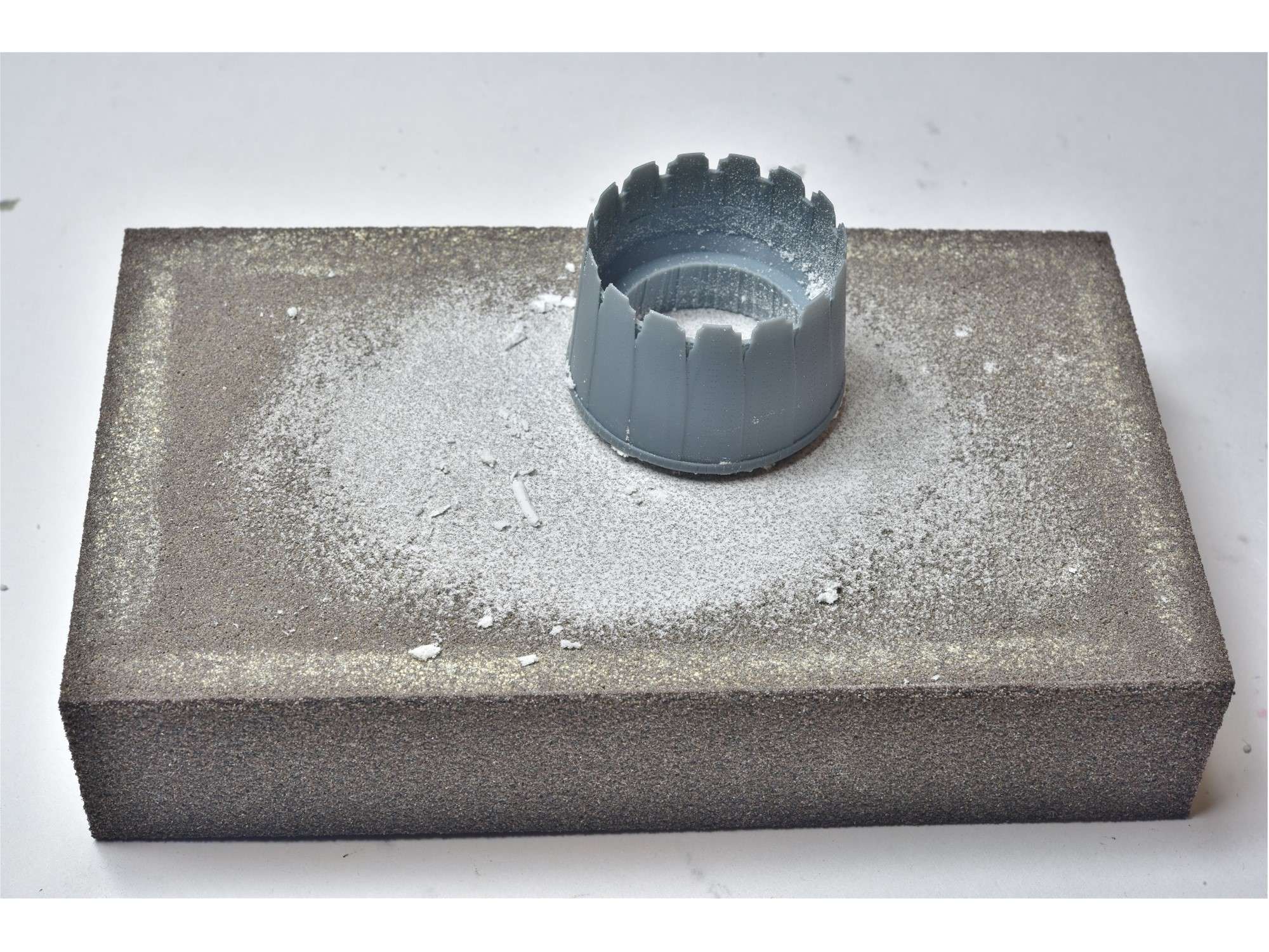
Unlike what the instructions call for, I’m sanding off the entire bottom of the nozzle, which removes a few millimeters of interior detail, in order to get a stronger fit with the kit parts as you'll see below. This small detail will not be missed once the engine assembly is assembled and painted. Here I’m using a flat sanding belt on a flat plastic holder, to keep the bottom of the nozzle as flat as possible. On the sponge sanding block, the rocking motion and flexible surface creates a rounded edge, which you don’t want for final sanding.
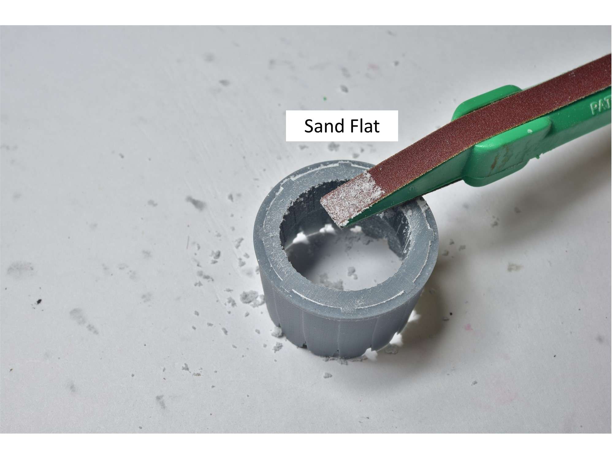
The sanding is complete with a light buff with a 1000 grit sandpaper sponge.
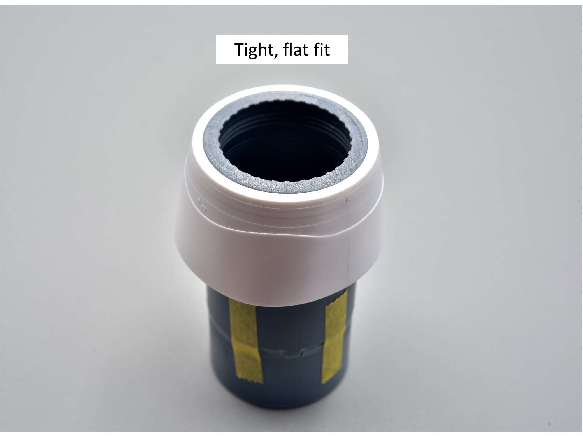
This is the main goal when the ResKit resin and kit parts are glued together. You want this fit to be as flat and flush as possible and it looks like the nozzle diameter is perfect.
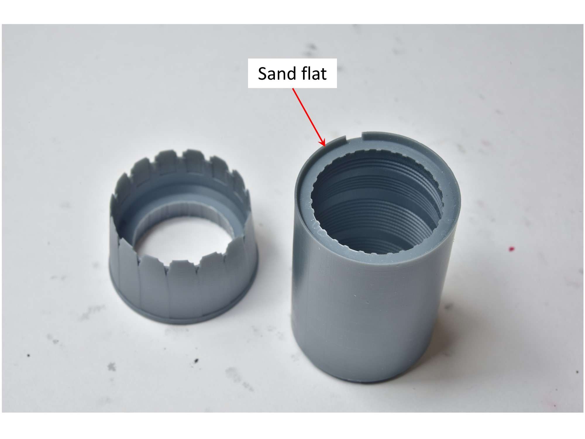
Here is the top of the flame-holder with the recess and notch, that the nozzle fits into. With the base of the nozzle sanded off, I sanded off this recess as well.
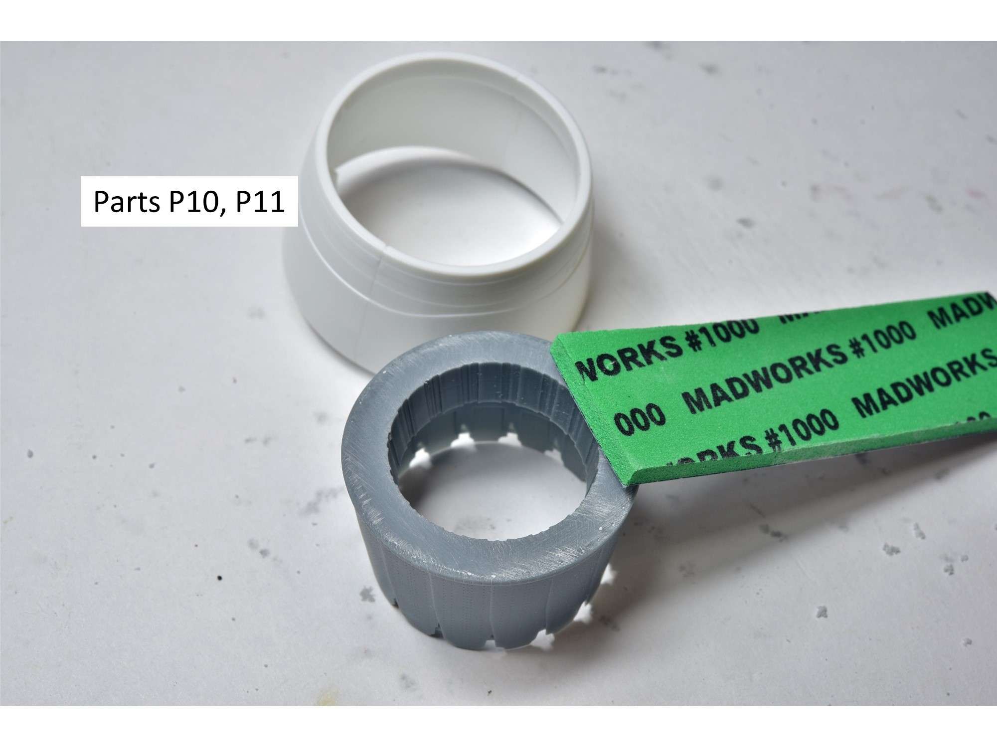
In order to fit the KesKit flame-holder into the engine fairing, I glued into place a thin strip of 0.5 X 4mm styrene into the kit parts P10 and P11, which turned out to be perfect.
And this is the reason for my departure from the ResKit instructions, in order to get a tight and very strong fit of the resin engine to the rear of the fuselage. With this wide and flat surface, the engine nozzle can be glued on at the end of the build easily, with no fuss with finicky recesses or notches in the resin parts, which are not as strong. Further, you can glue the “best side” of the nozzle upwards as you choose, without the need to lock it into a specific notch on the flame-holder.
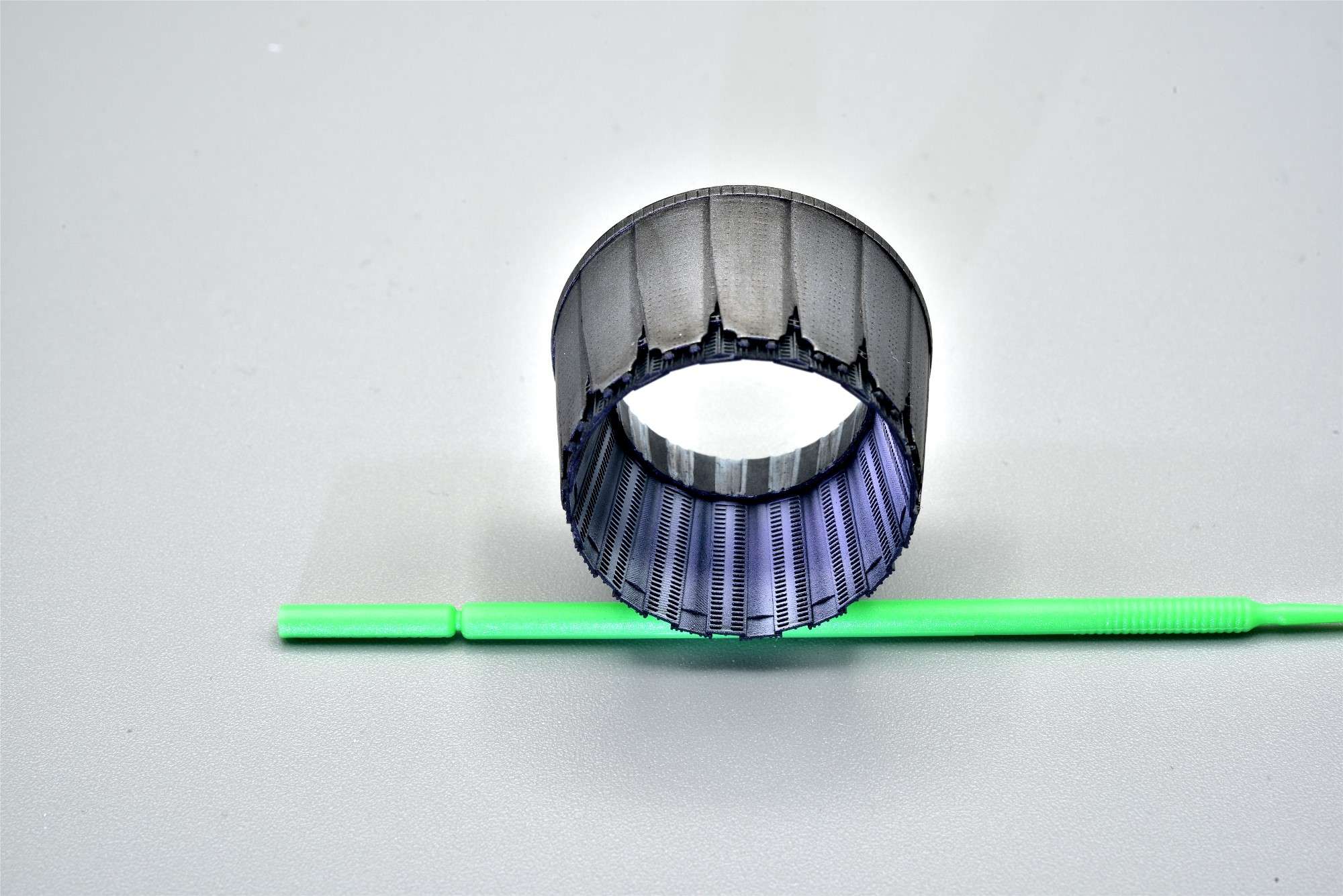
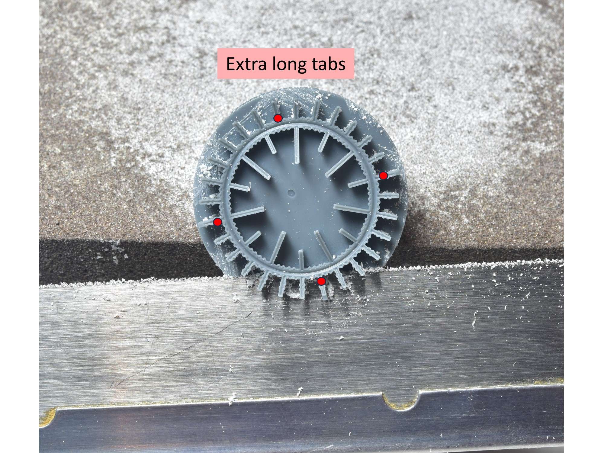
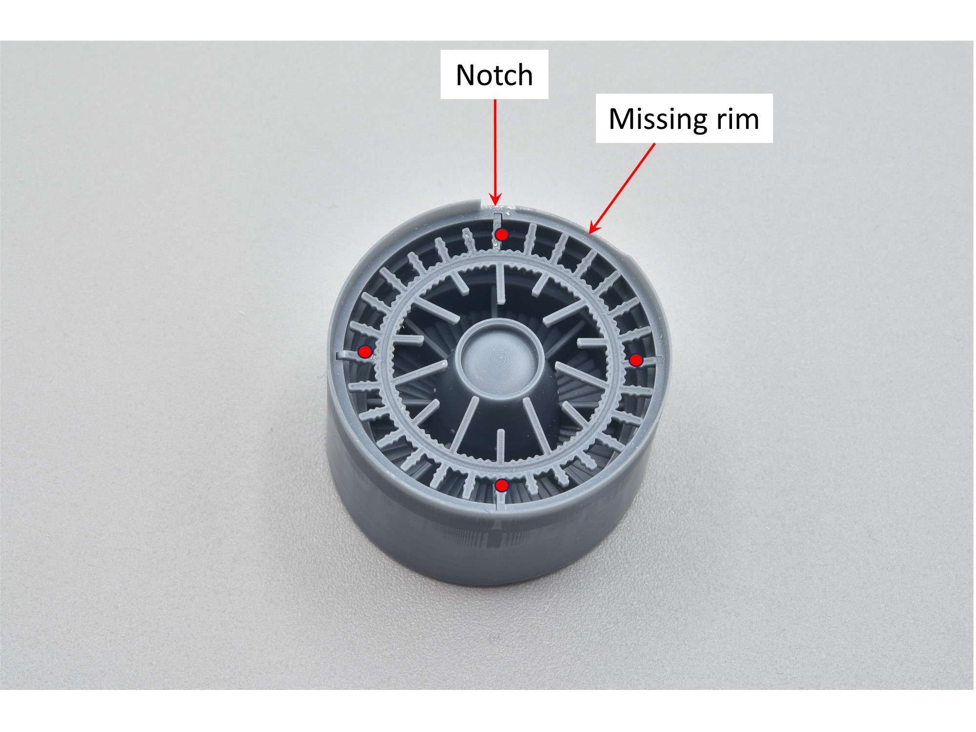
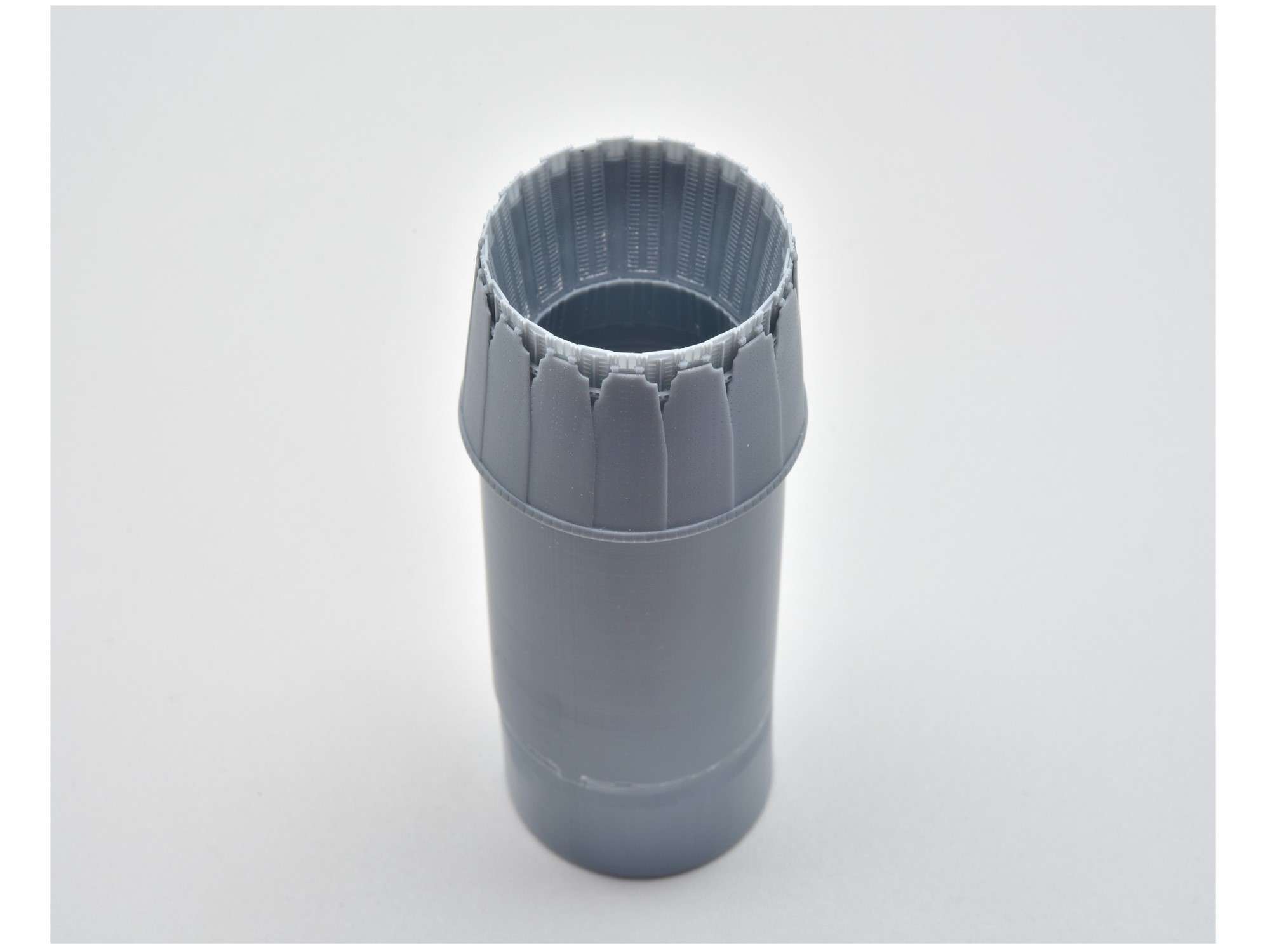
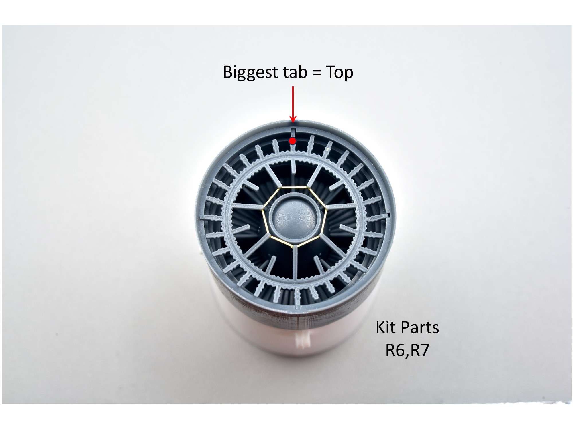
The last resin block I cut was across the very detailed circular grid at the front of the flame-holder. I dreaded doing this, because breaking the delicate parts seemed inevitable, but at least I had the kit Part P25 to fall back on if I made a mess. There are 4 tabs that are a bit longer than the rest that I marked with red dots, that fit into slots of the engine duct.
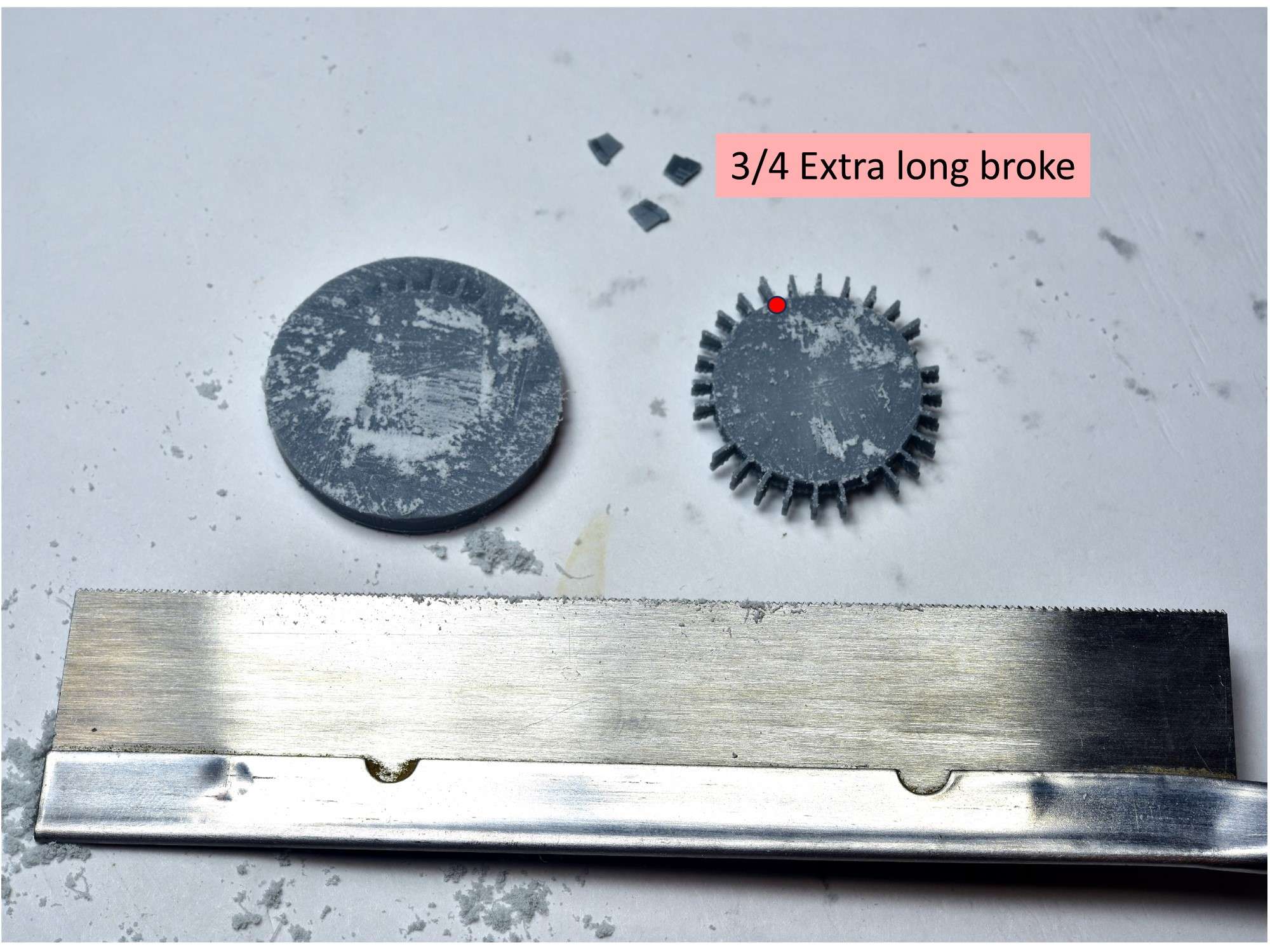
The reason I noted the 4 longer tabs is because 3 out of the 4 broke off when I cut the assembly off the block, with the only remaining one marked with a red dot.
") I’m guessing it’s because they flexed more with the saw and due to the extra stress, broke more easily than the shorter tabs? At this point, I was fairly certain that I would be using Part P25 instead!
I’m guessing it’s because they flexed more with the saw and due to the extra stress, broke more easily than the shorter tabs? At this point, I was fairly certain that I would be using Part P25 instead!
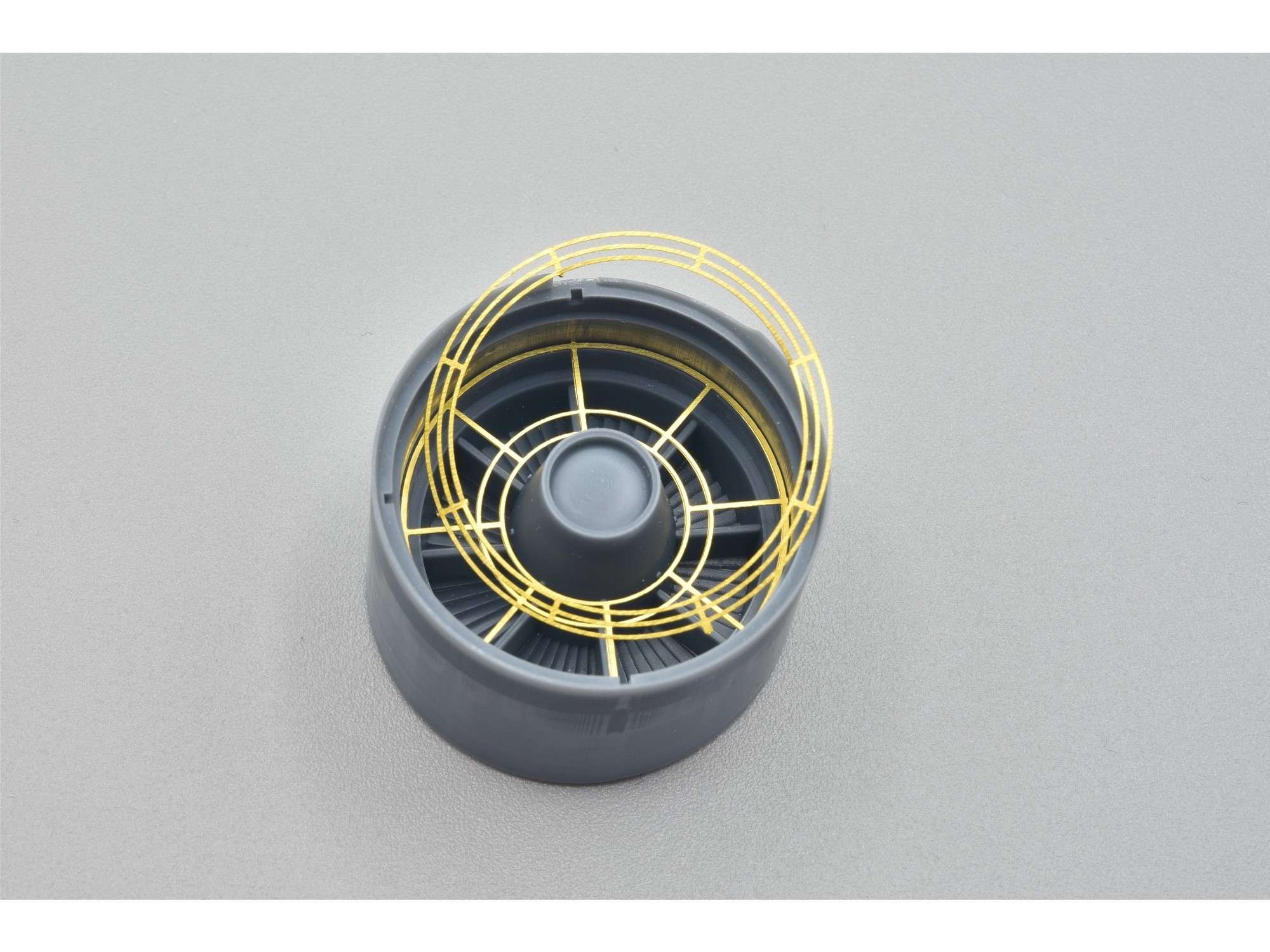
Much to my surprise, I was able to cut off the extra backing from all of the tabs and glue the broken parts back on with CA glue, without any more drama. Using styrene cutters, the key to cutting the backing was to cut horizontally with the assembly to the base of the tab, which broke the vertical portion of the backing naturally, snapping it off. From there, a #11 knife was used to clean everything up. The repaired tabs are quite strong, with a fairly large amount of CA glue applied from the rear where it can’t be seen.
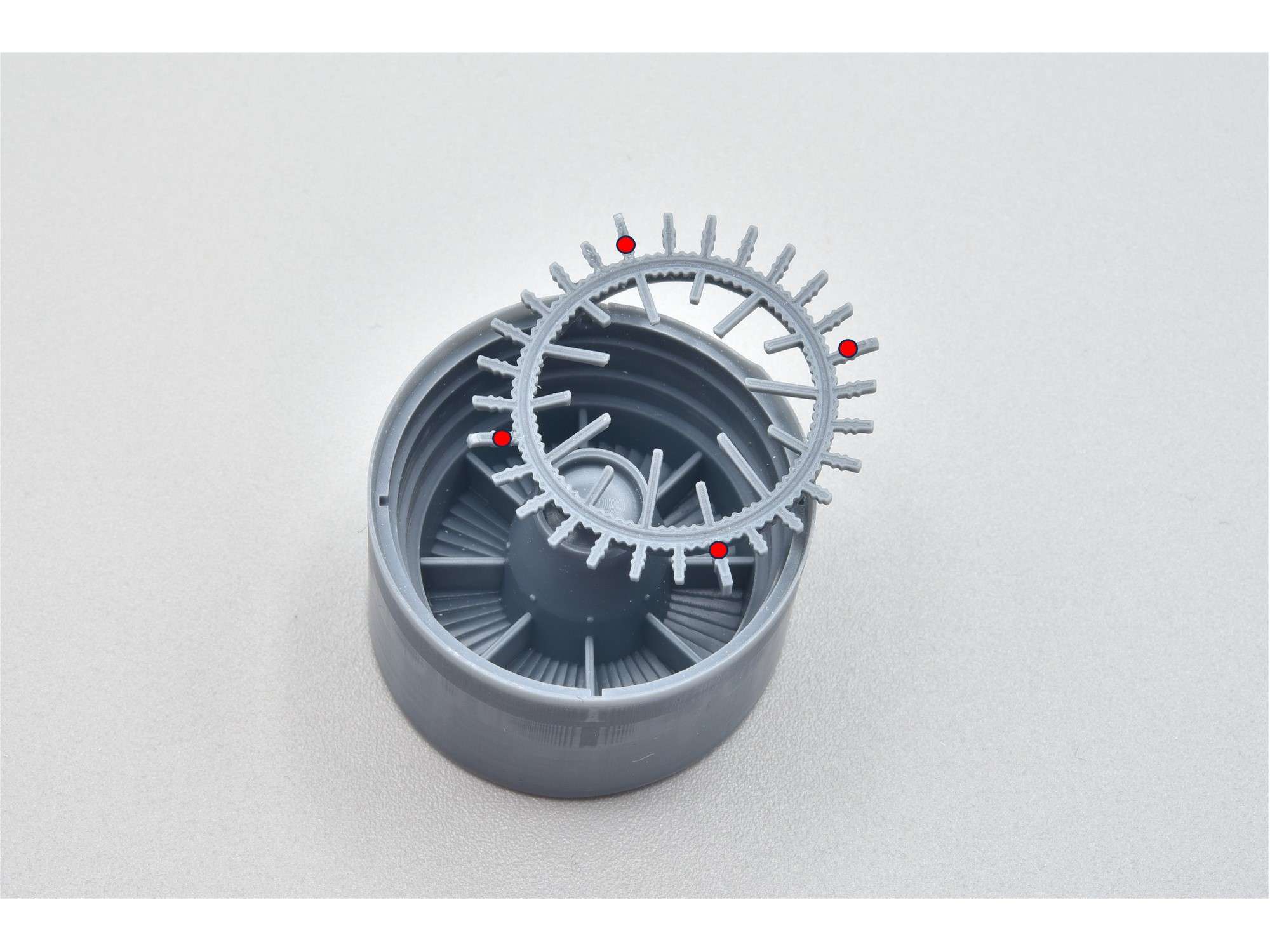
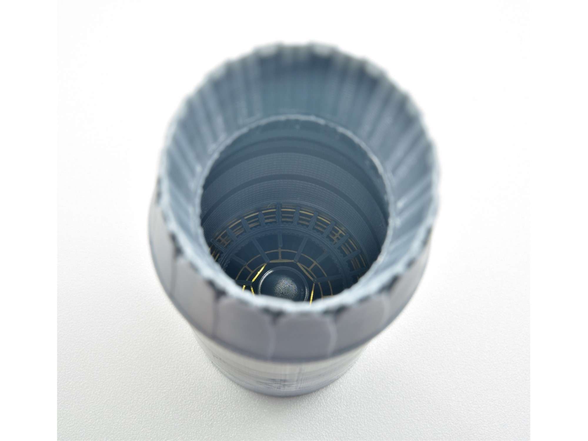
Here it is dry fit into the base of the engine assembly. My kit came with a broken rim on this part, which isn’t a big deal because it will not be seen when fully assembled.
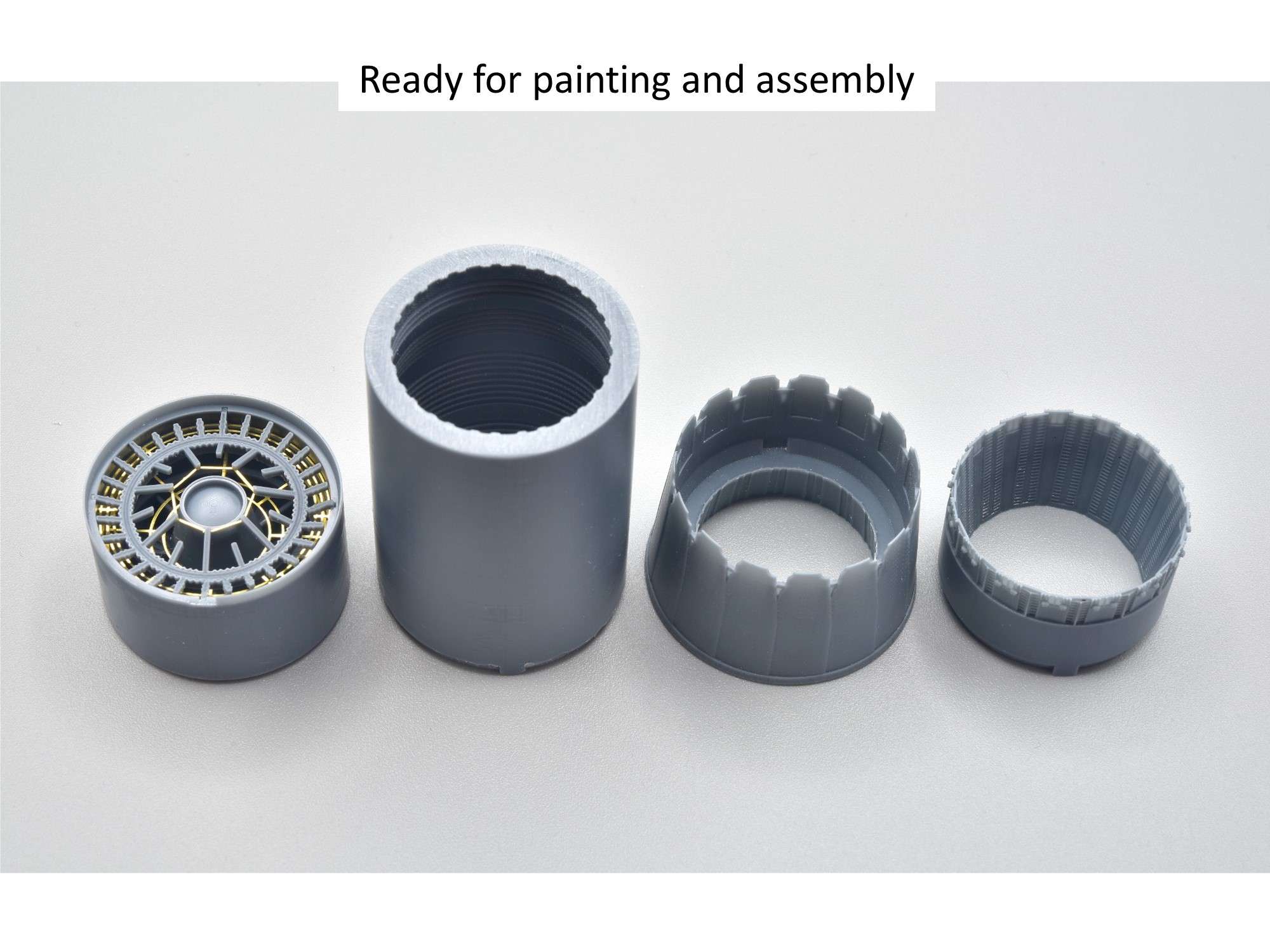
There are 3 more brass parts that need to be added below the resin assembly.
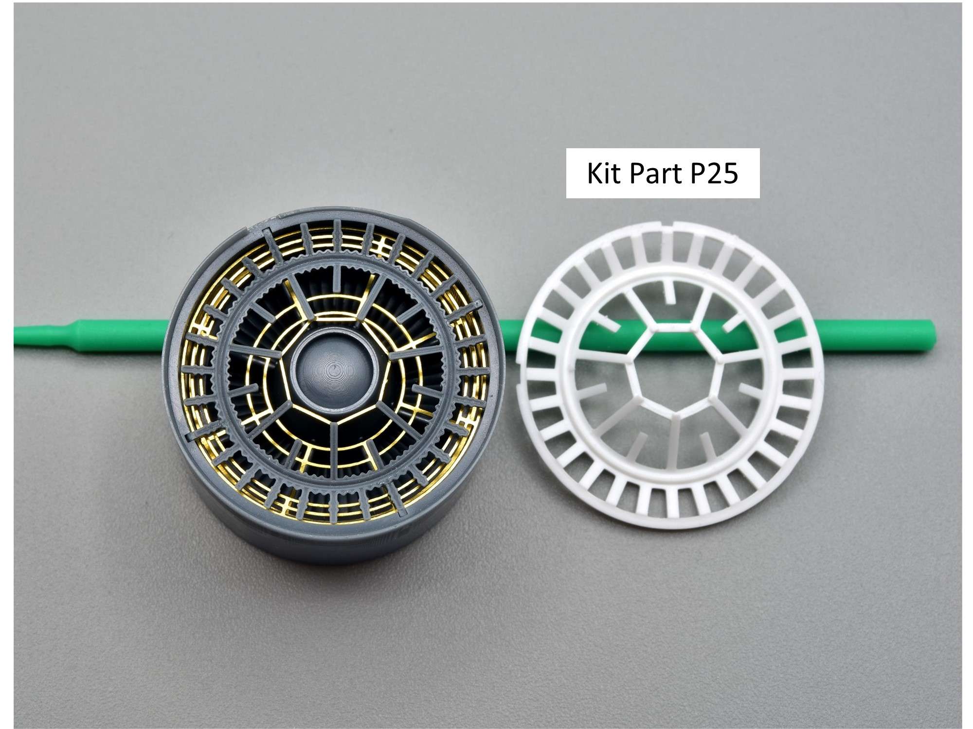
Final dry fit assembly, compared to the kit part. Pretty impressive engineering by ResKit!
So now it was time to deal with how the front of the KesKit engine was going to fit into the fuselage. I had the same problem and solution with my CF-104 build, so I sort of knew already what to do. Using the front part of the kit engine that slides into a groove in the engine bay, I cut off about 1” of it and the front tabs.
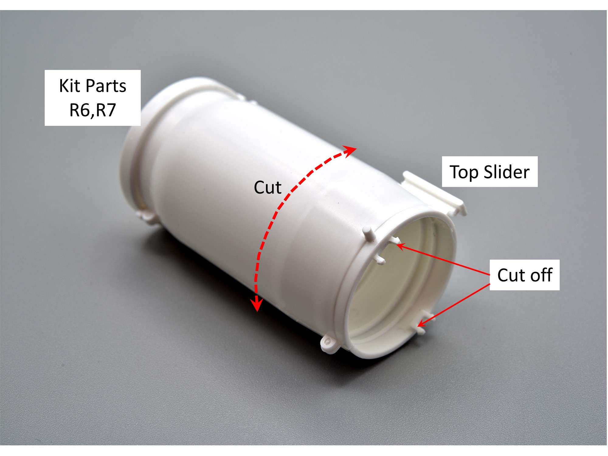
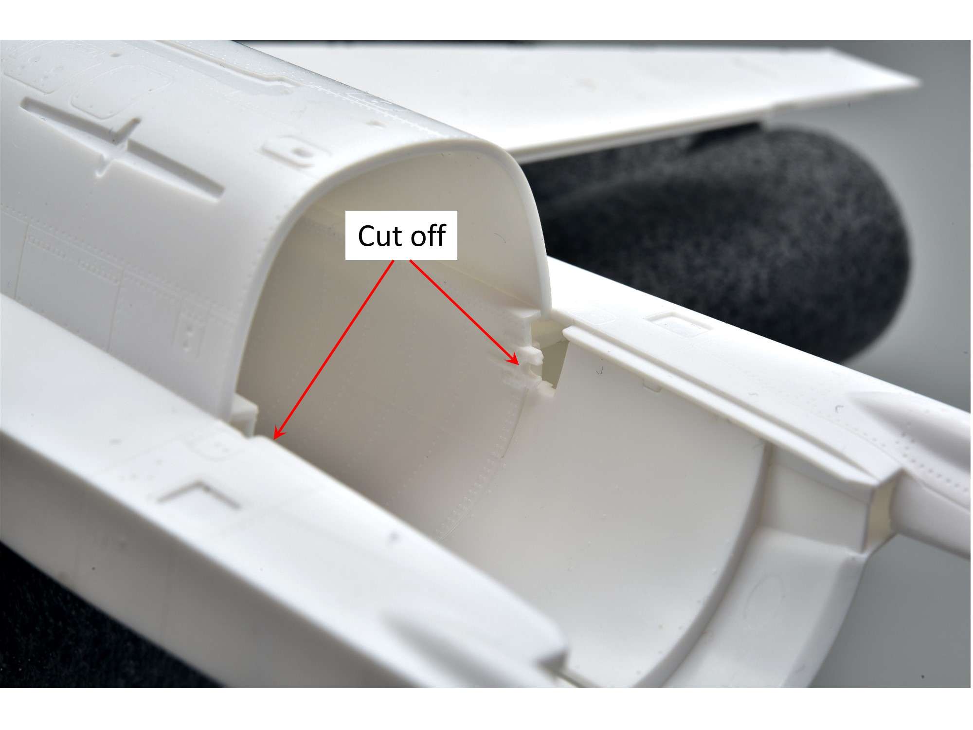
I then cut off two pin locks in the engine bay that normally hold the kit engine.
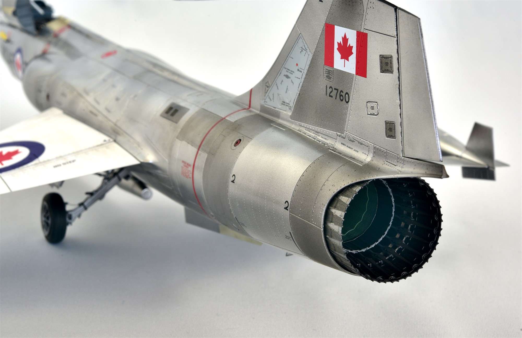
Before I glued any engine parts together, it’s important to figure out which way is up and which way is down in the engine compartment. I looked at several pics of PW100 engine pics from the rear and came up with all sorts of angles that I found confusing, but most of them were for F-15’s which appear to have the engines installed a few degrees out from what I finally settled on, like the pic below from an actual F-16. Note the flat top to the heptagon with longer arms coming from the corners.
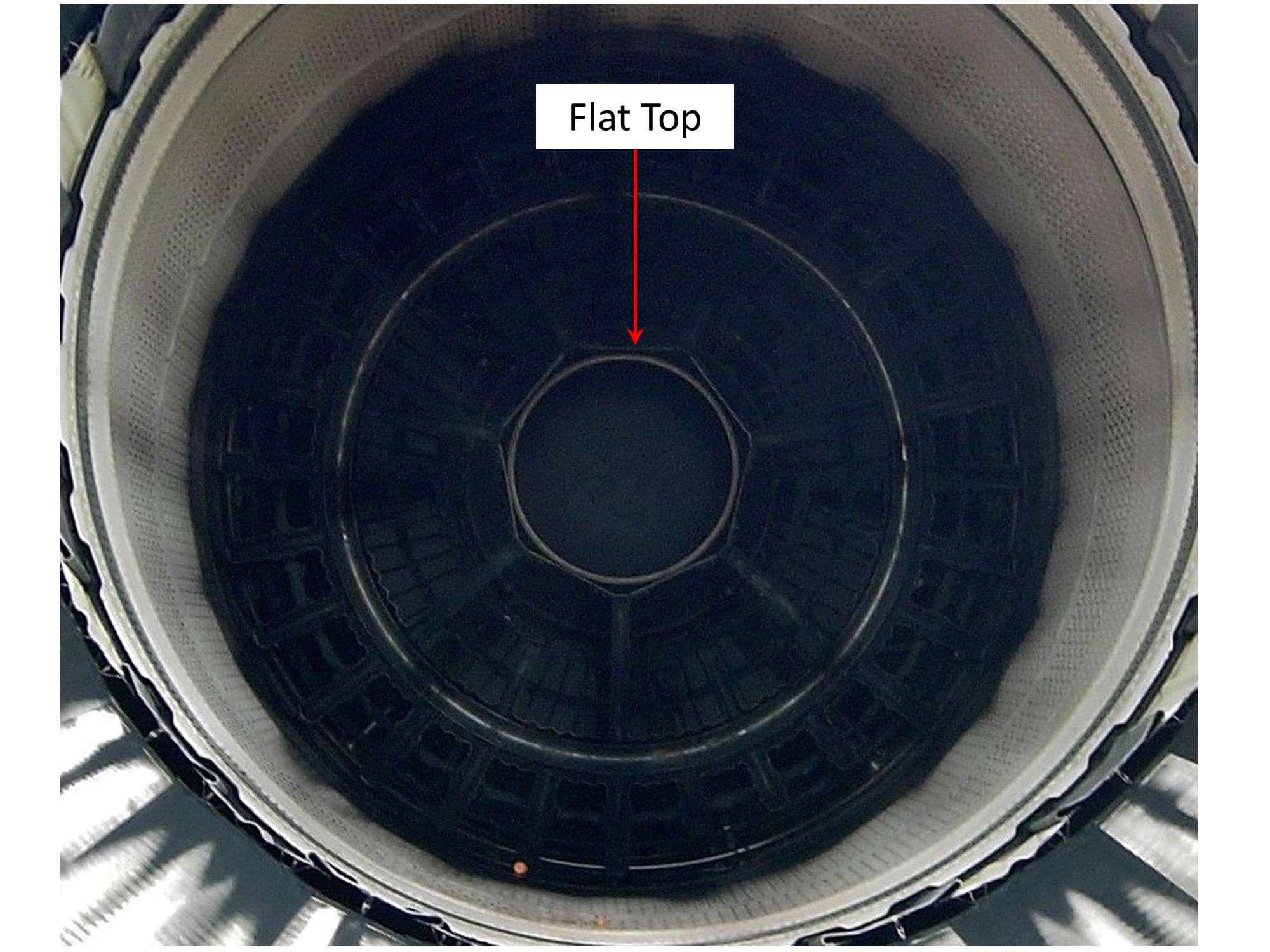
So I set the “Top” accordingly and marked it with a pen, which coincides with the deepest tab of the resin assembly, which is no doubt there on purpose. The front portion of the kit engine I cut off was then glued to the base accordingly.
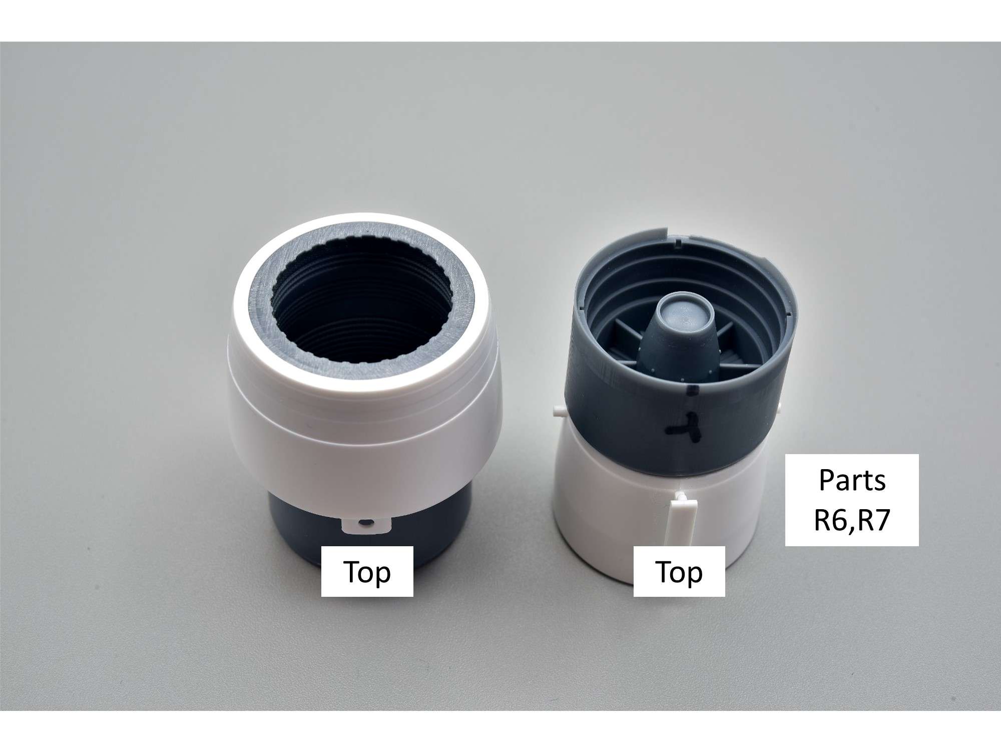
The sub-assemblies indicating which portions go to the top. While the assembly on the right is glued together, the rest are only dry fit at this point.
The groove at the top of the engine bay is quite long, thanks to it sharing the same part as the Block 50 kit, which has an entire engine that can be removed for display. This kit only uses the rear of the groove, which is all I need.
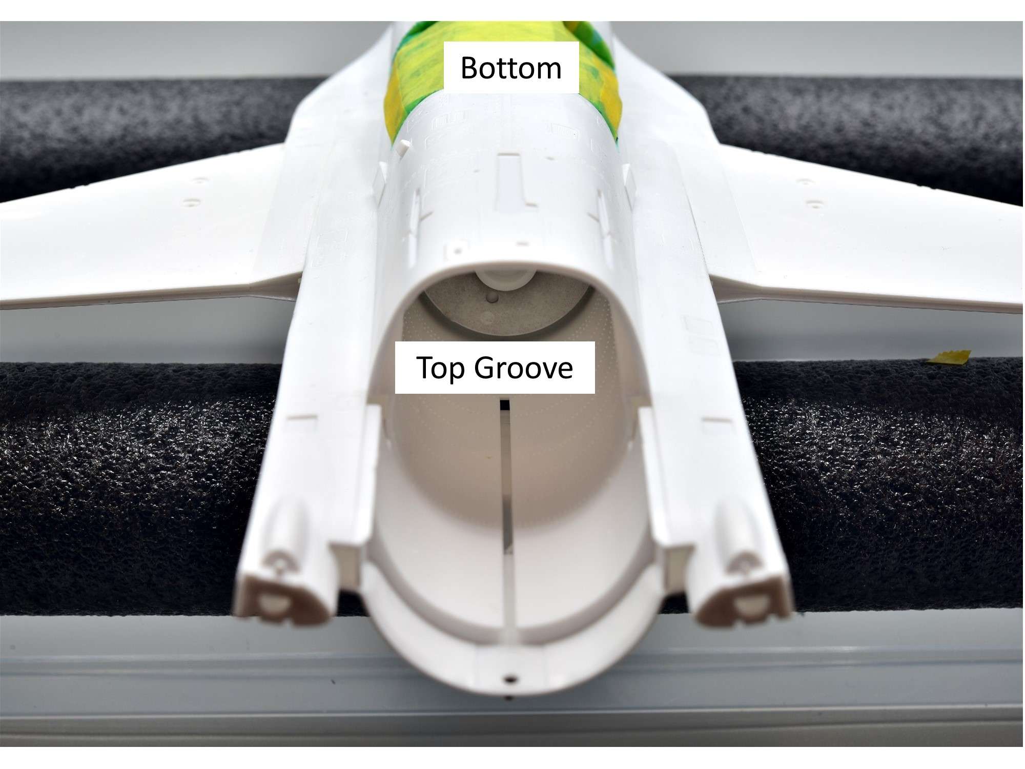
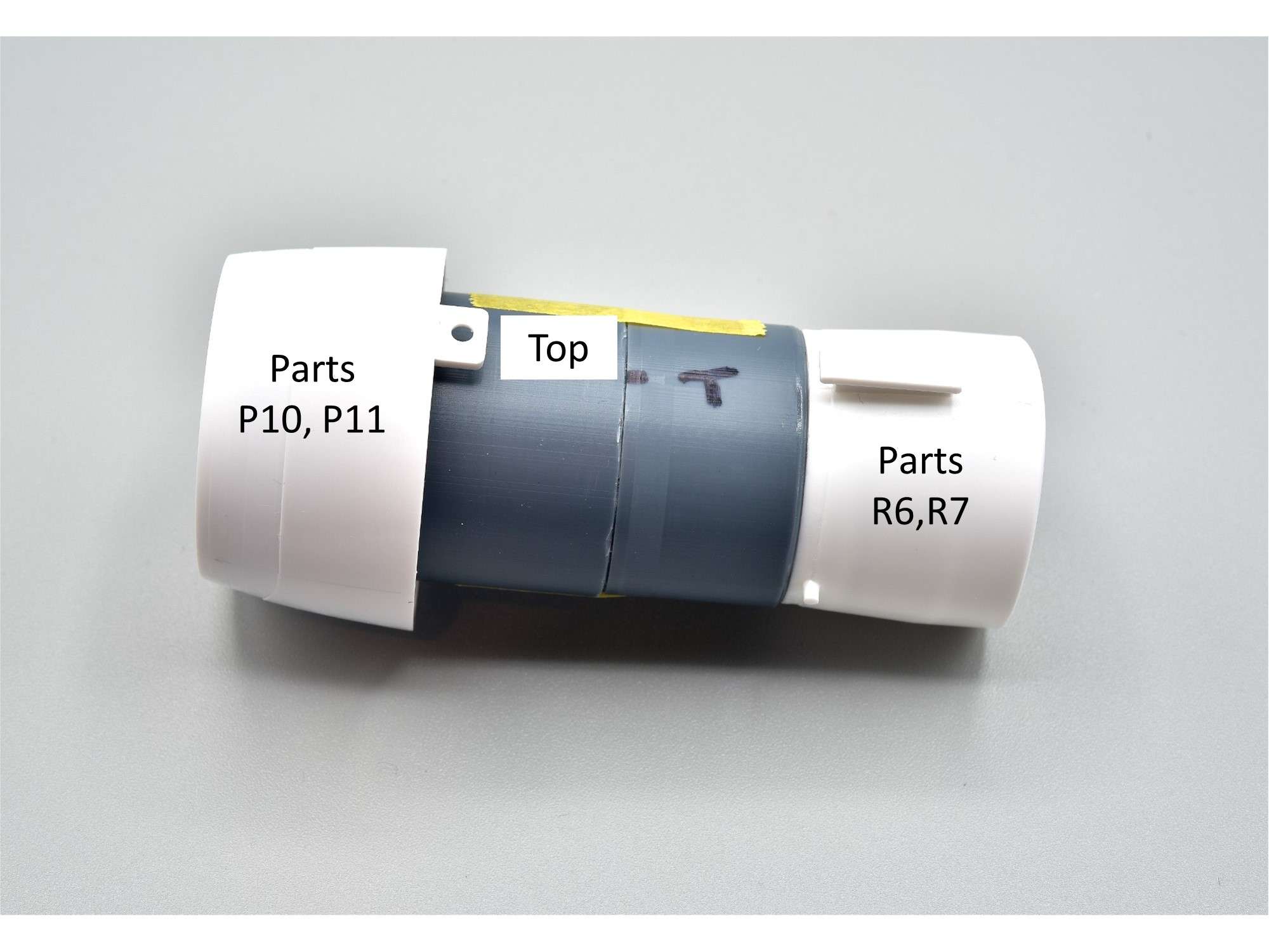
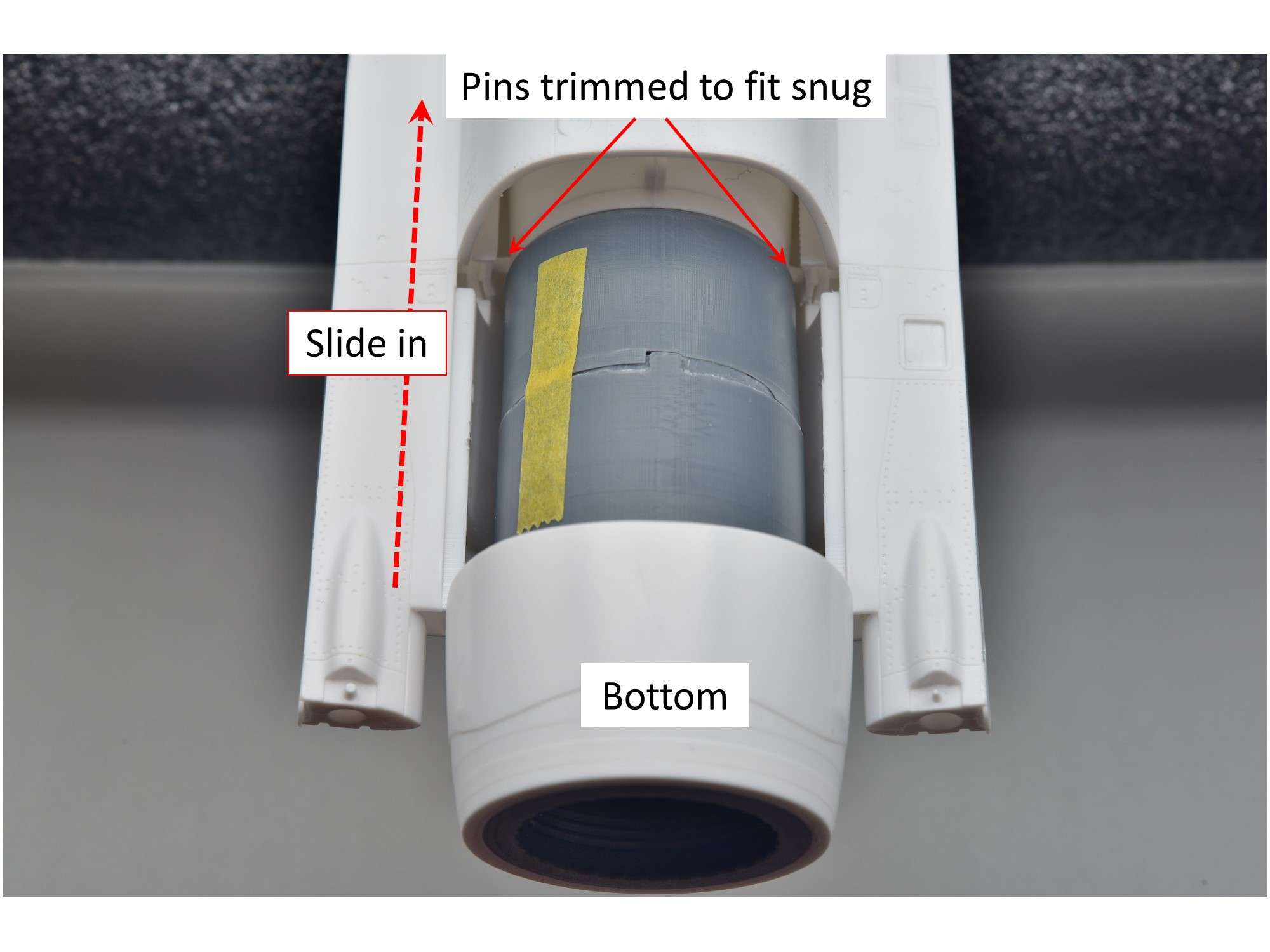
The Engine sub-assemblies now just slide into place with ease, after trimming the side pins of the kit parts to allow clearance, while still remaining snug. This fit is solid, so once everything is glued into place, the engine will be very secure when bounced around.
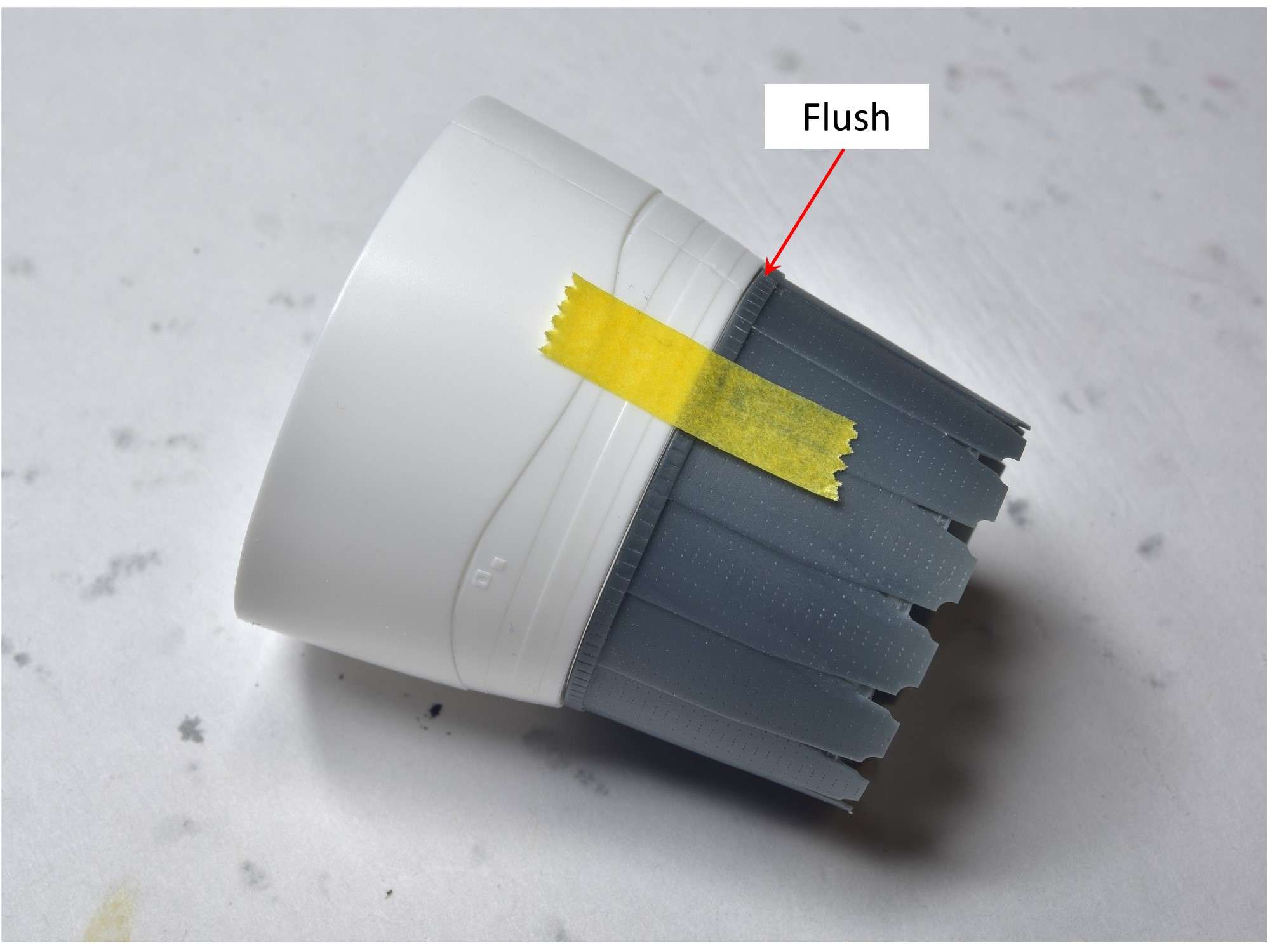
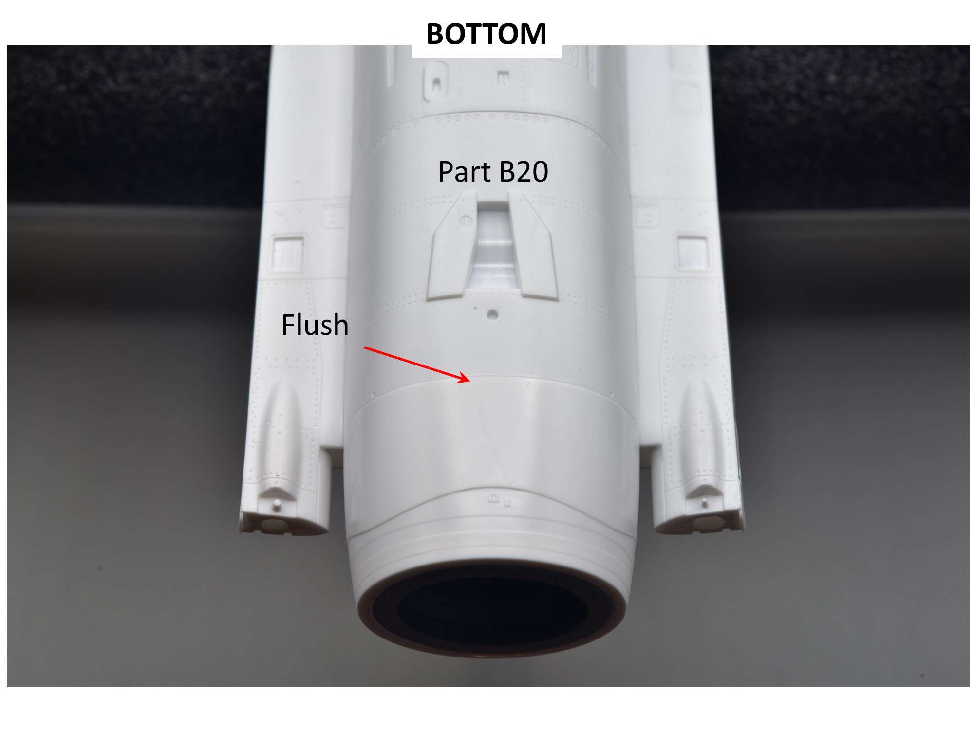
With fuselage Part B20 dry fit into place, the engine fairing fits fairly flush on the bottom.
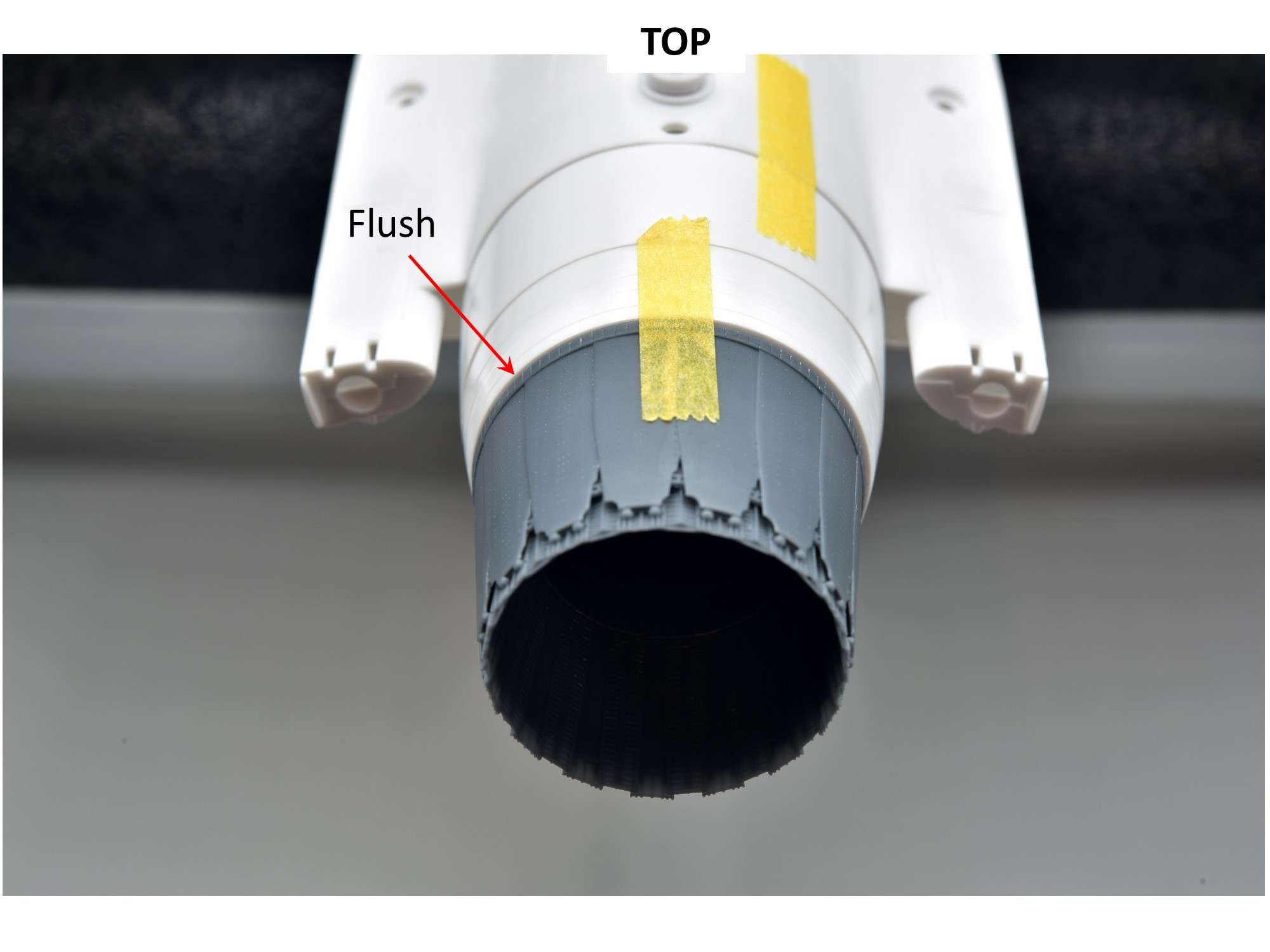
Same thing on the top, showing that the hole of the fairing lines up with the hole in the fuselage top perfectly.

And the candle on this engine cake, the rear nozzle, which can be glued on at the end of the build with no fit issues later- and no gaps.
So the current game plan is to paint and detail all of the engine parts, then install the engine with the kit fairing and other fuselage parts to ensure that everything is smooth and looks natural on the outside, which will take a little light sanding. From there, I’ll mask off the rear of the engine and attend to the other kit assemblies on the tail.
One might ask why I worry so much about the interior of an engine that I'll rarely see again, even with a flashlight. The answer is, "It's Fun!",
at least to me, which is a big part of what modeling is all about. Thanks for checking in.
Cheers,
Chuck
-
-
Another masterpiece from Guy! Just awesome and all the special little details you added really show through. Again, I really love the paint chipping, because you nailed that realistic look that is so hard to replicate.
Cheers,
Chuck
-
Really nice work Duane and I must say, very different than most Viper builds due to your unique and really cool looking subject. I'd like to steal some of your ideas but everything is so different than mine, there aren't many that would apply. Good catch on adding a cap to the intake navigation lights which is often missed and here's another tip if you don't know already: The panel lines around the pitot tube on the nose cone aren't real, so they should be filled and sanded smooth. The pitot covers when the jet is one the ground (red with a RBF flag) often leaves a mark, which is what Tamiya was apparently trying to replicate, which they also did on their F-15 kits.
Cheers,
Chuck
-
March 24, 2024
I’ve been doing some more research on what differences there are between my subject, a Block 25 and the other Viper block variants. One thing I found was that the so-called reinforcement plate (#7 of Cross Delta set above) around the radar blisters behind the nose cone are actually RAM panels (Radar Absorbent Material) instead, so I have edited my post accordingly. Apparently these items are being added to older Vipers, but they aren’t on the Ghost Scheme ones I have pics of so far, so I won’t be adding them.
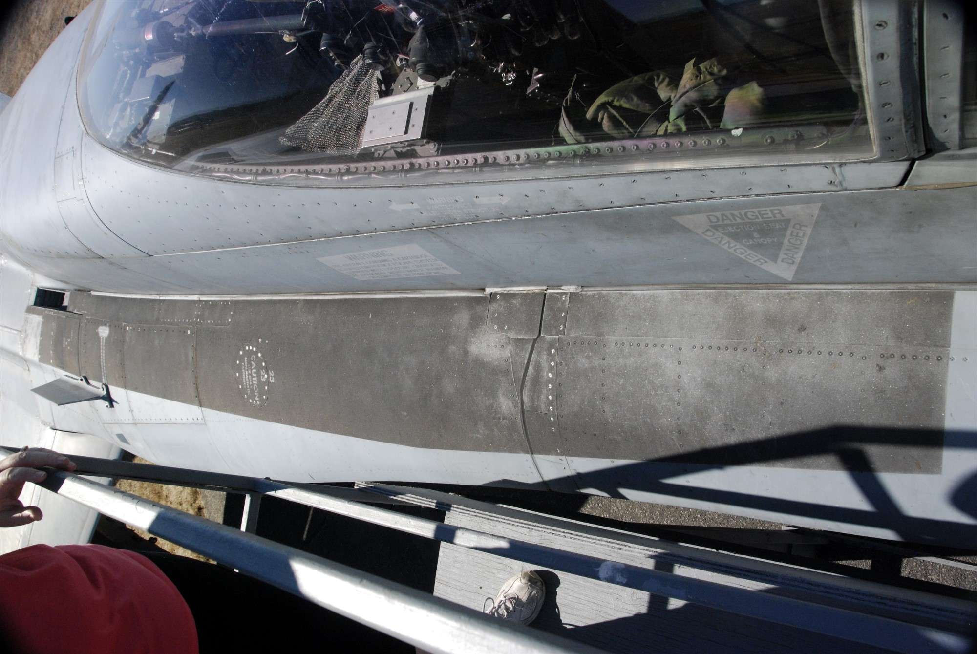
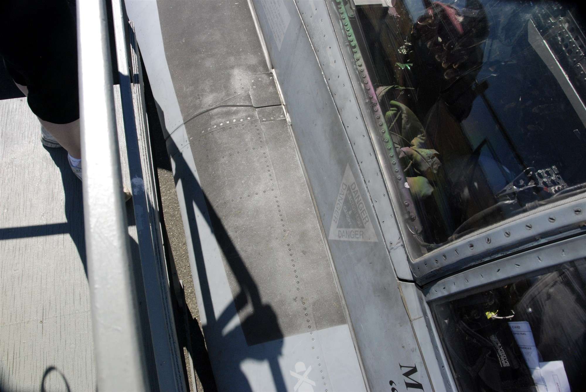
Another very small item I found was that Block 25’s have a small reinforcement plate which I’ll call a strap because it's long and thin, right behind the canopy hinge. I don’t have a great picture of this area on my subject, so the one below will have to do, but sure enough I can see that it’s there. The other Viper I have pics of above, 86-0299 which is a Block 32, doesn’t have them as expected.
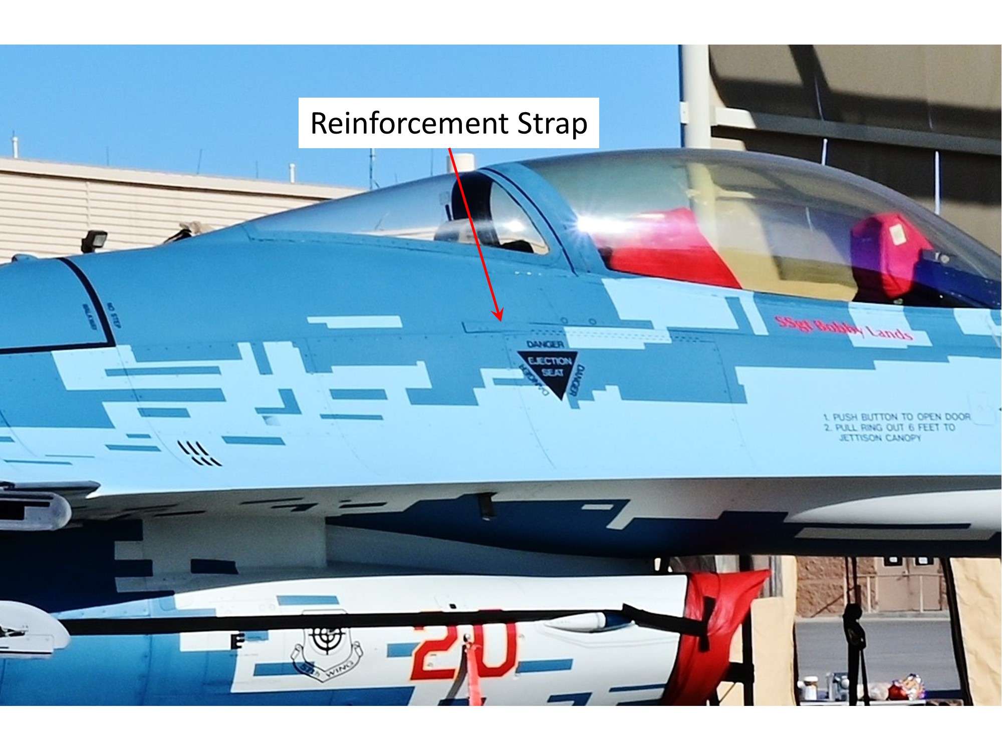
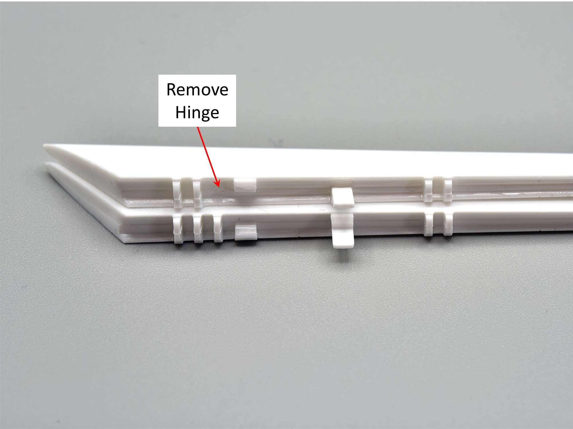
So I’ll be adding this small strap along with the other reinforcement plates to make my model as accurate as possible, which begs the question: “If you’re so worried about tiny accuracy, why not alter those 3 fingered front flap hinges to 2 like you should have all along!” Well, after this complicated modification was bugging me with all sorts of justifications for not doing so as described earlier, I finally caved and got on with it. Deep down I knew I would eventually, as maybe a few of you did as well. As they say, "No Guts no Glory"!
After lots of thought about how to do this effectively but still allow the flaps to be left off for ease of painting later, this is what I did. First, the outboard finger was cut off very carefully with a #11 knife, to retain the surface detail of the flap, while also retaining a concave surface to the flap/wing boundary. The remnants of the “flaps down” tab that was cut off beside it on the right was retained, since it provides a good glue anchor join when the flaps are cemented into place. The “Flaps up” tab as I’m using is to the right of that again, are unaltered.
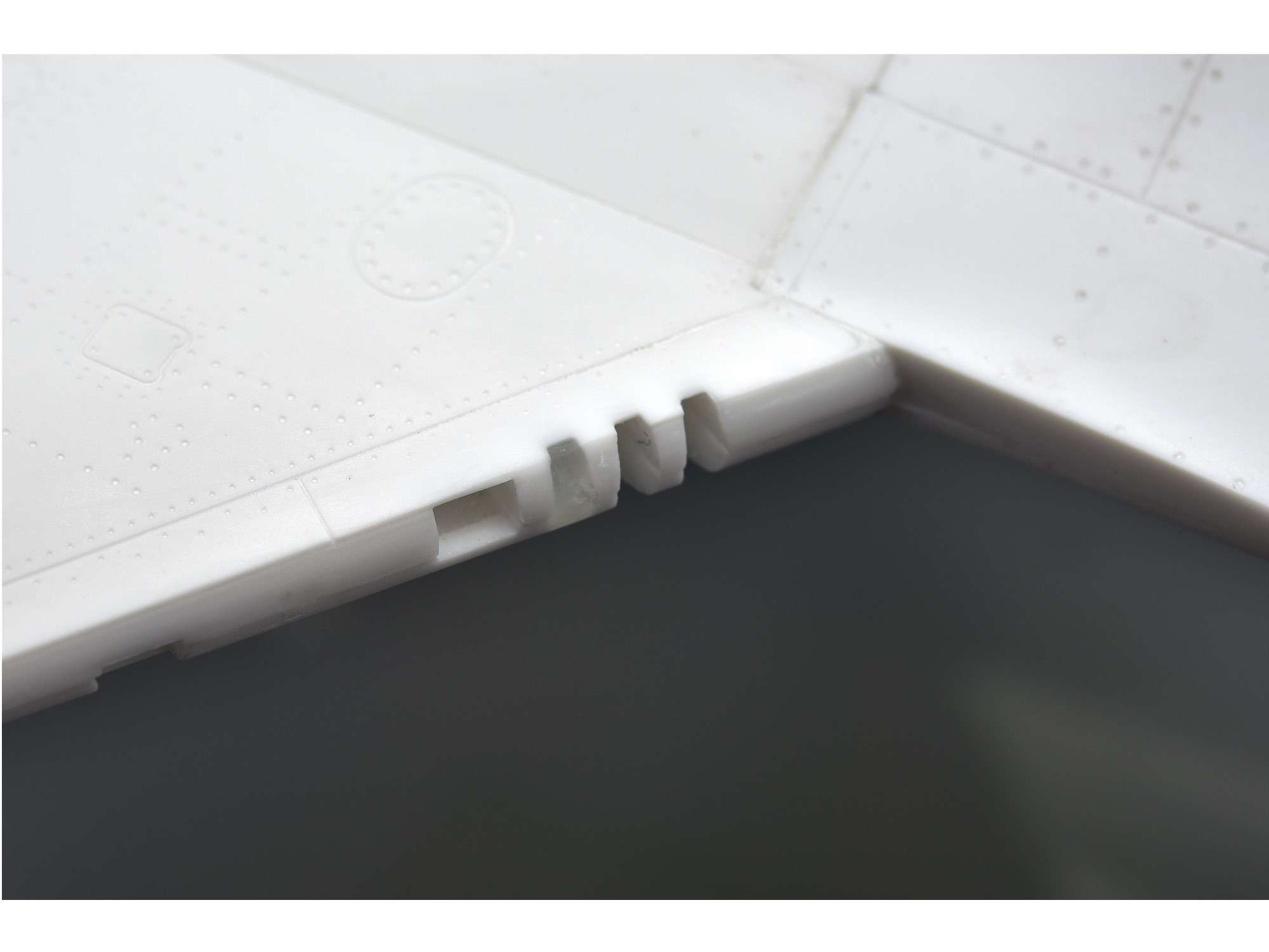
After carefully cutting the finger off of the flap, I then filled the recess where it used to fit with CA glue. I prefer CA glue for almost all my filling, because it’s strong, dries almost immediately and I can sand and shape it quickly, in this case to conform to the adjacent contours of the wing/flap surface. A very iterative procedure of applying CA glue and accelerator was used to achieve the end result.

The other side, which is a bit hard to see since the CA glue is clear. While the surface under the flap can look like almost anything as long as it doesn’t impede the fit of the flap, the top portion that you can see must be flush with the rest of the wing.
The top fit is pretty darn good now, knowing that it will be even tighter after the application of glue when the flaps are glued into place permanently near the end of the build.
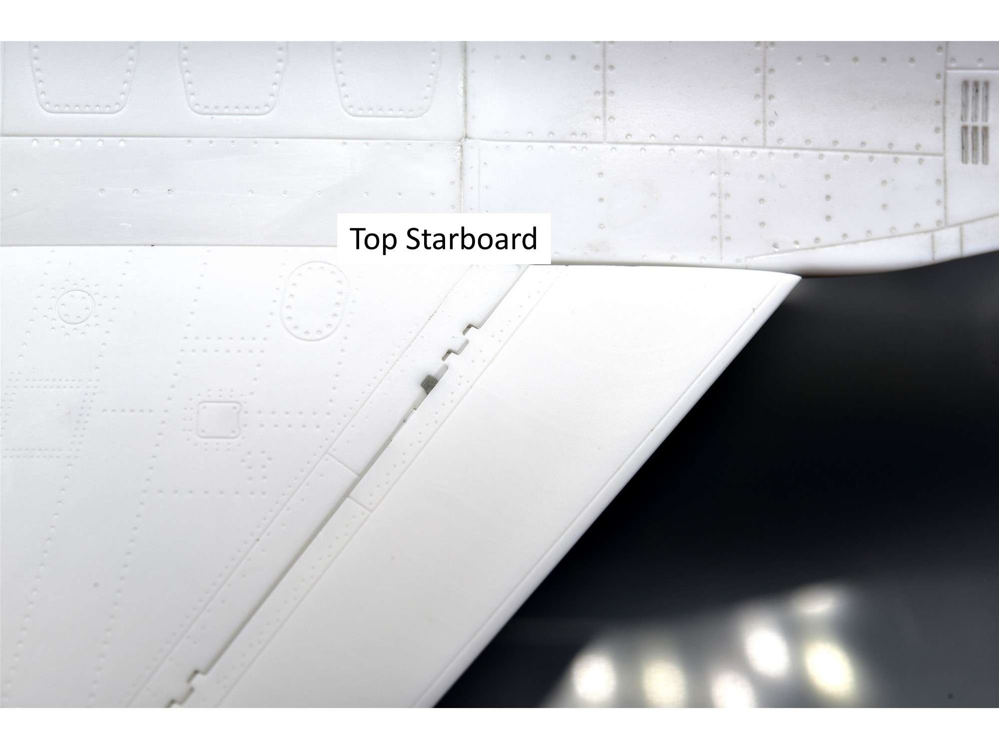
The bottom of the wing/flap join was a bit trickier with all of the complex adjacent detail here, but I’m sure it will look fairly natural after a coat of paint.
There, I finally caved on the flap hinge to make this Viper as close to a real Block 25 as possible. The exact lateral location of the 2 vs 3 fingered hinge is not clear, but based upon pics in Jake's Viper Guide, I think it looks close enough by just deleting the outboard finger. Now maybe I can finally sleep at night.

Cheers,
Chuck
- scvrobeson, Marcel111, Greg W and 19 others
-
22
-
1 hour ago, ALF18 said:
Oh, and for the flaps...
Hornet trailing edge flaps and ailerons will bleed down after hydraulic power comes off (i.e. when engines shut off), if they were not already down when shut down.
Those are good reference pictures.
The leading edge flaps will stay where they were when shut down. Generally, to prevent problems when starting and resetting the flaps, pilots will select flaps down (either half or full) just before shutting down the engines, and the leading edge flaps will go to 12 degrees down. The trailing edge and ailerons will droop 42 and 45 degrees respectively when set to full.
So - if flaps set to UP/AUTO prior to shutdown:
-leading edge will stay up, flush with wing
-trailing edge and ailerons will droop over the course of an hour or so to the fully-down position.
If flaps set to HALF or FULL prior to shutdown:
-leading edge will be 12 degrees down
-trailing edge and aileron will end up fully down within about 30 minutes of shutdown.
In other words, it's rare to see a parked Hornet with the flaps up. Leading edge maybe, but trailing edge and ailerons will droop quite soon after shutdown. Sometimes, when loading missiles onto the fuselage stations, techs will push the flaps up with their backs to have better access, but they will slowly droop again afterward.
ALF
Much like "Pig" with his F-16 advice to me that I very much appreciate, there's nothing better than having a real F-18 (CF-18) pilot who knows what he's talking about if you are building a Hornet. Go with ALF18's recommendations and you will be fine.
Cheers,
Chuck
- Mel and geedubelyer
-
2
-
Be careful of the rear flaps angle with this kit. The flaps rest downward, but not beyond the bottom of the fuselage. The lowest flap hinges have them rest much lower which is wrong. The solution is to alter the hinges before attaching them to the flaps. Here's a few examples:
Cheers,
Chuck
- Mel, chaos07 and F`s are my favs
-
3
-
Hi Mel, you are doing a really nice job on one of my favorite jets. As for the anti-skid surfaces, I would sand them down a bit so that the rough bits are knocked down a bit for scale. This will also make the surface look worn, which is what you want. I would then dirty them up with pastels, like Tamiya "OIl Stain", which I use on almost everything I want to make dirty.
Here's some reference pics I took of the anti-skid surfaces on an F-18A, albeit a Canadian CF-18 version, which should be similar to the American F-18C. Note that small details like screws and fasteners still show through the rough surface. Also note that the surface isn't as dirty towards the rear, where foot traffic is much less than the cockpit sides.
Cheers,
Chuck
F-16C Block 52+ "Raven" Polish Air Force - First LSP
in Works in Progress
Posted
Those prices are smoking good, even if you just kept the needles!
As much as I have used and bragged about my Iwata CM-C+ over the past few years with it's tiny 0.18mm needle, my "go-to" airbrush these days is back to my older HP-CH workhorse with the regular 0.3 mm needle, now that I use MRP paints whenever I can. The MRP paints spray very well without thinning, assuming the orifice is big enough, but the CM-C+ struggles and often sputters with this paint after a few minutes. Right now this thin needle airbrush is restricted to Alclad or other extra-thinned paint where it excels, while the rest of my painting goes through the HP-CH.
One other observation. Both of these airbrushes have a screw at the bottom to further fine-tune the pressure and paint flow. I never use it, so I recommend buying the cheaper version without them, since I don't find them helpful.
Cheers,
Chuck