

tomaszhajzler
-
Posts
145 -
Joined
-
Last visited
-
Days Won
4
Content Type
Profiles
Forums
Events
Posts posted by tomaszhajzler
-
-
Hi everybody!
I'm back after my holiday.
This is my most advanced project, but of course i can show you my earlier models. They are more normal . If I have time I promise show you some photos.
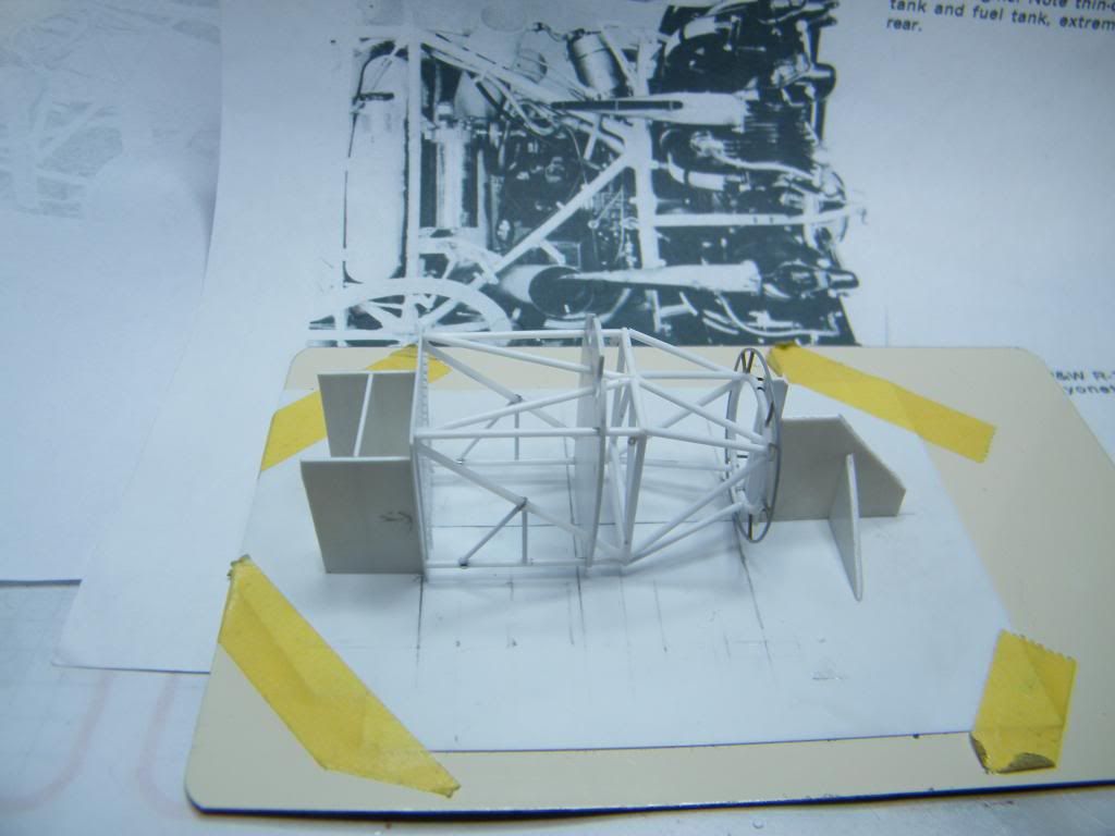
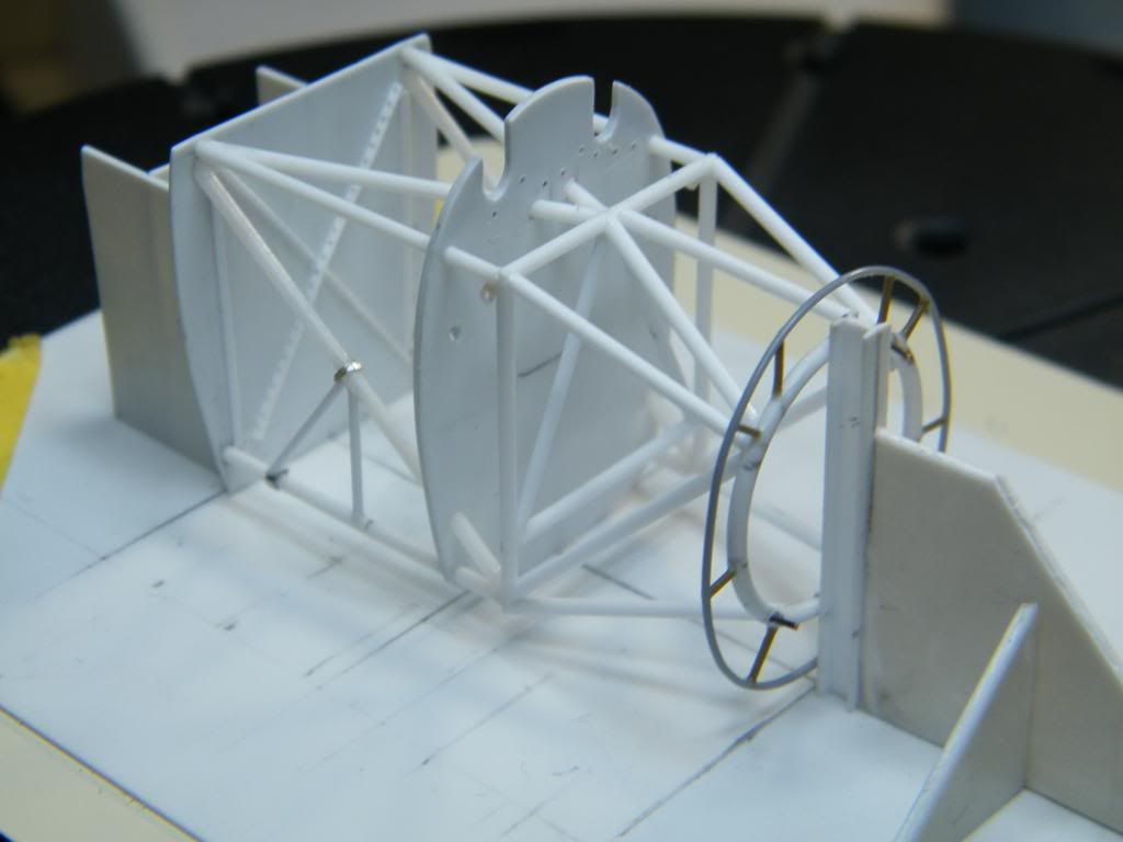
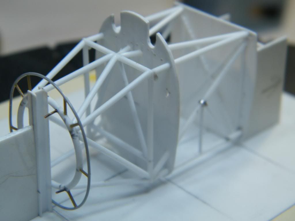
I suggest return to the front part of the fuselage. I decided, from the begining, to use Vector engine set dedicated to this model kit. I had to make engine mount. To this part was fasten thin oval ring. I considered to make it using copper wire and to solder all together. However I decided to use plastic. I fastened both rings to the base to get correct shape.
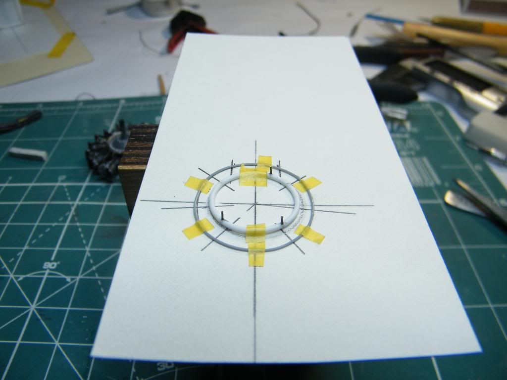
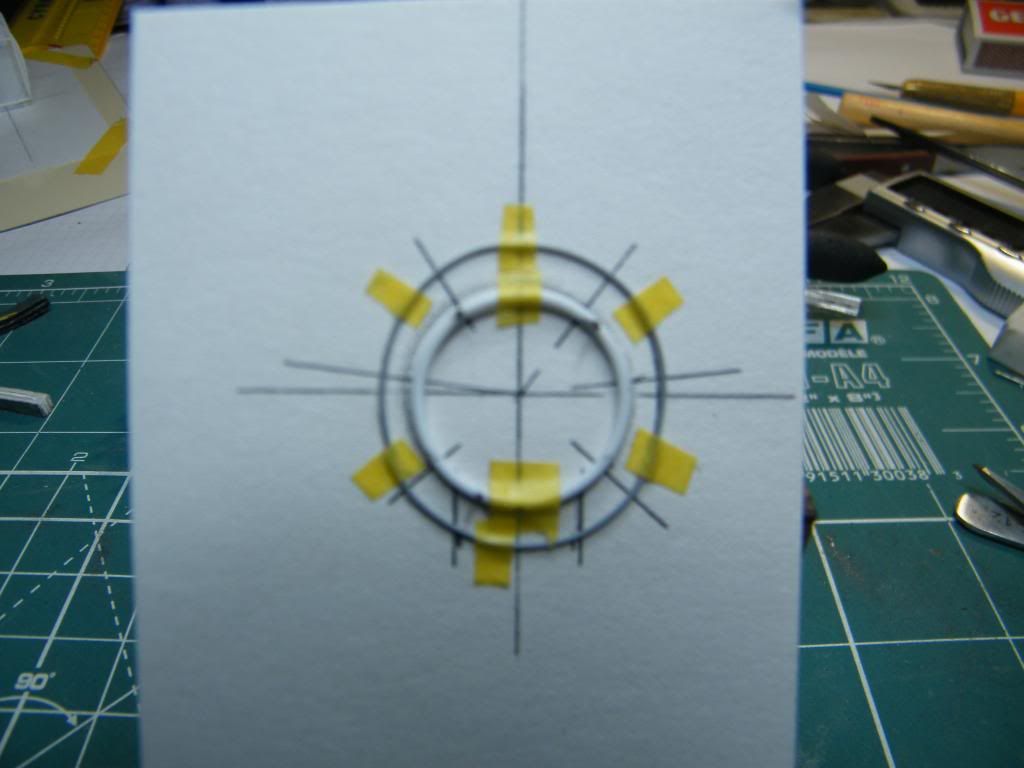
Next, once again, I gently glued all construction to the base, to join all together.
Regards
Tomasz
-
Welcome again!
Return to fuselage.
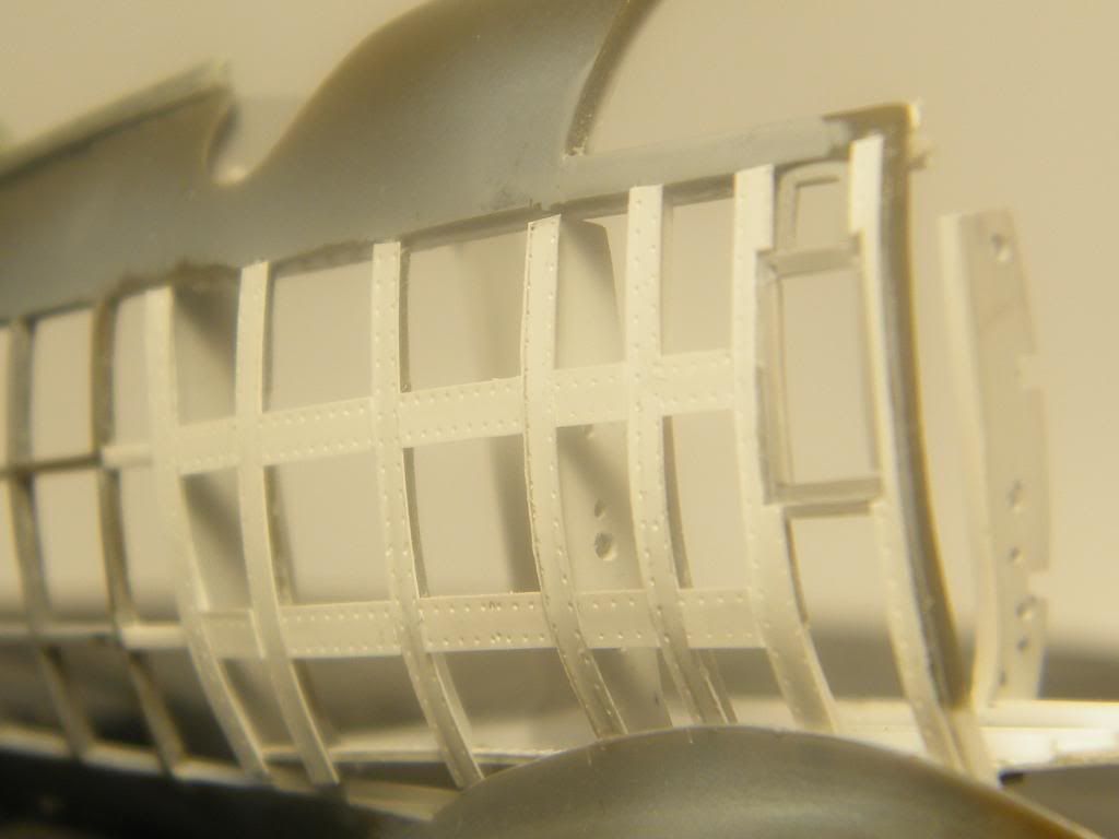
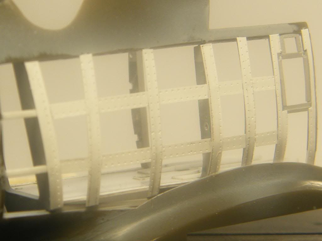
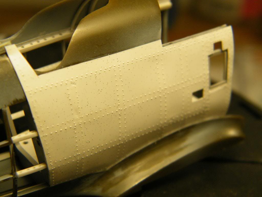
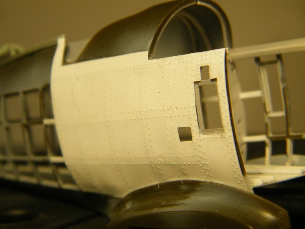
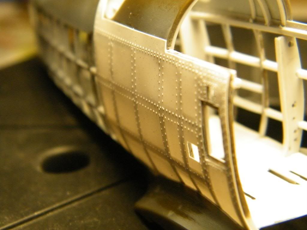
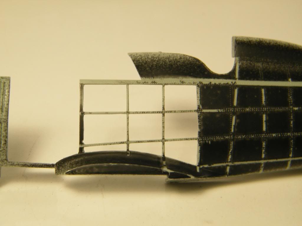
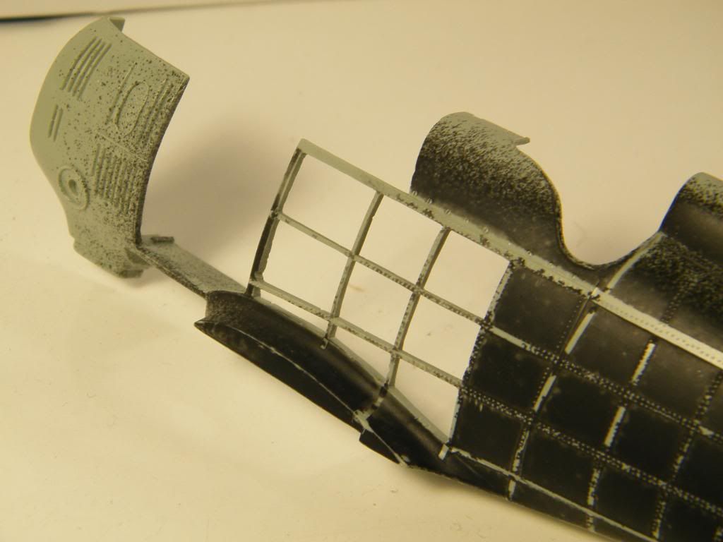
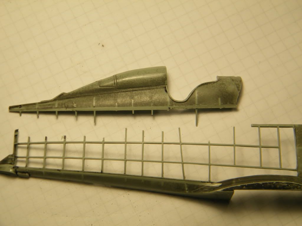
I made new skin in rear part, behind cockpit. If you remember we've got inside skin with imitation of frames and rivets.
So go to the outside skin. I had to m,ake it from two separate parts.
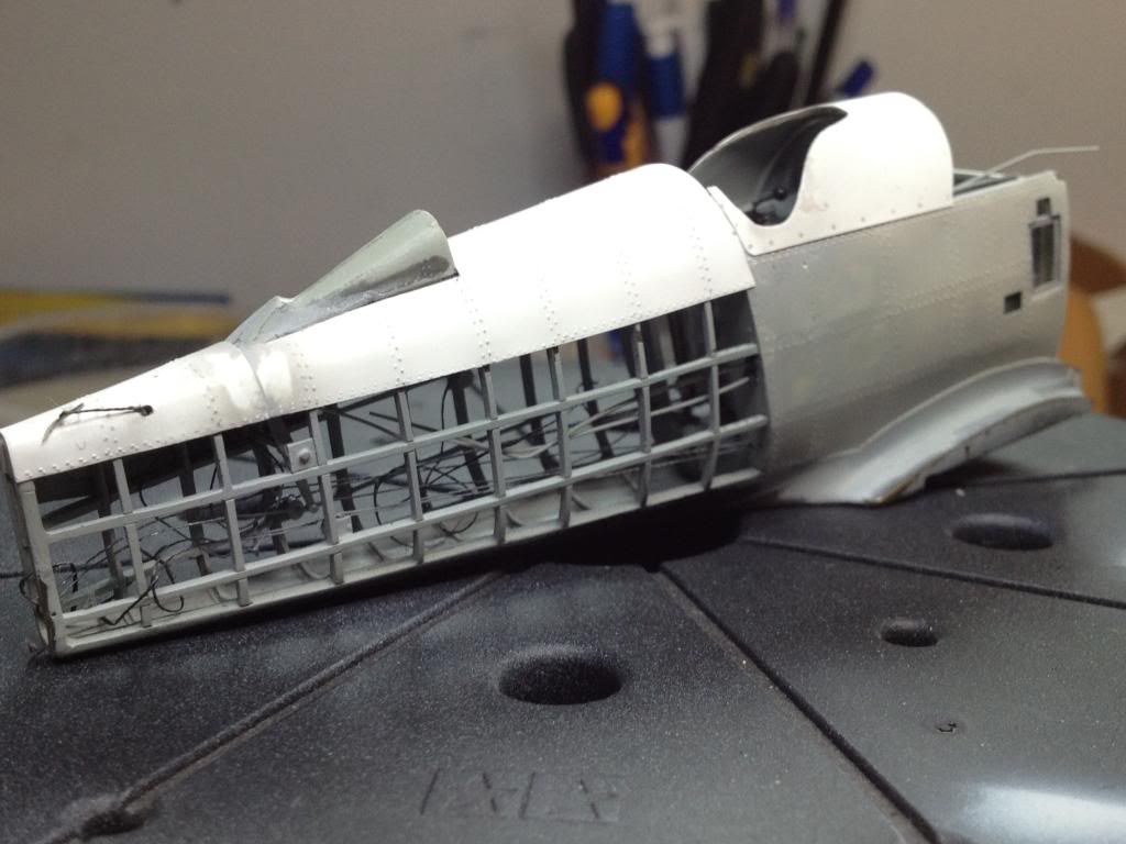
and next part of the skin. First attempt from alluminium foil.
But I think that rivets made in foil were bigger then in plastic. So i decided to made this part also from plastic sheet.
Regards
Tomasz
-
Welcome!
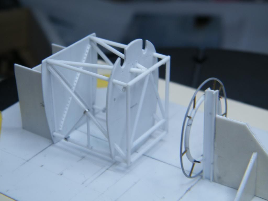
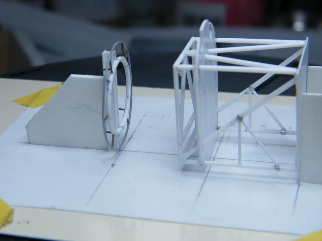
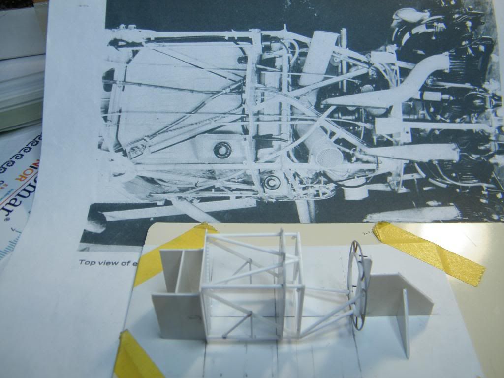
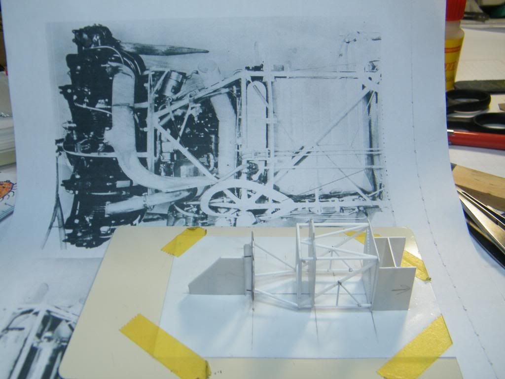
For a change I decided to handle front part of the fuselage. I used corell to scale down photos of engine compartment first. I prepared base of construction next, which help me to get correct geometry. I glued both frames to the base using few drops of CA glue. I added first struts of framework next.
When all construction became stiff I detached framework from the base using debonder. I had to do it to add more rods.
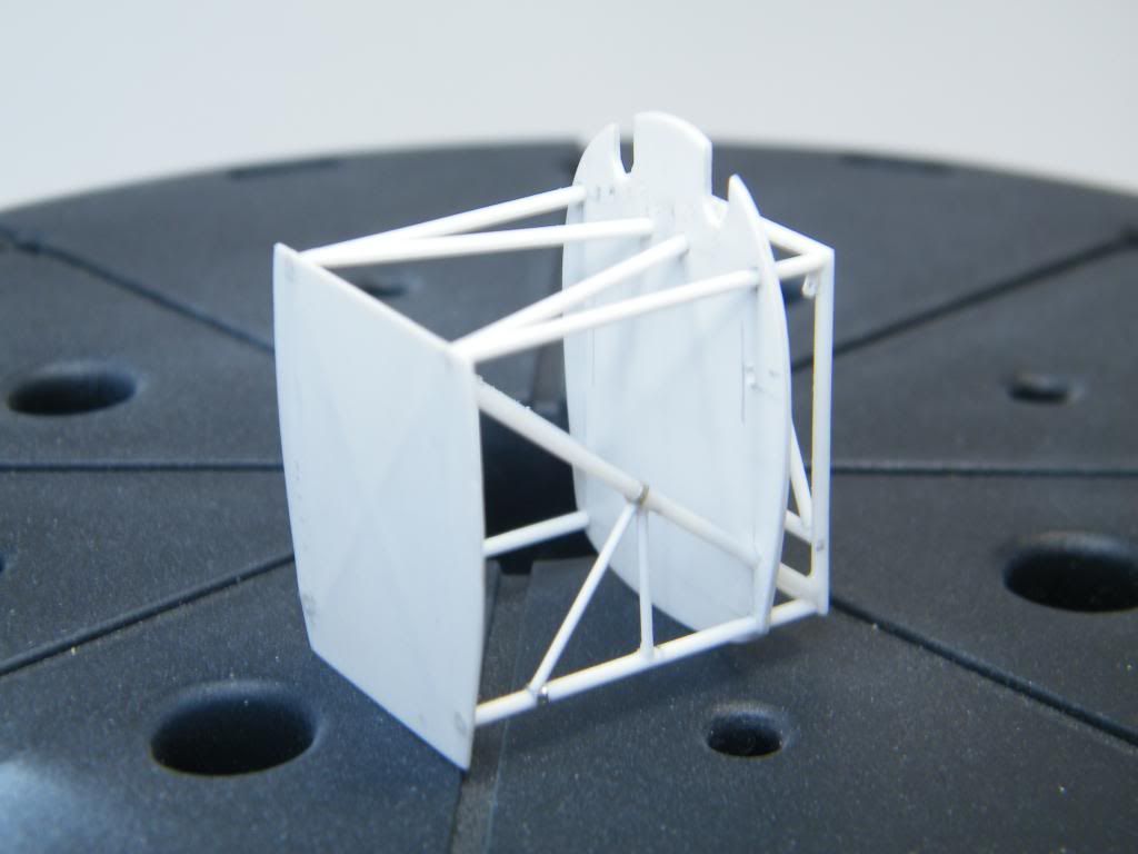
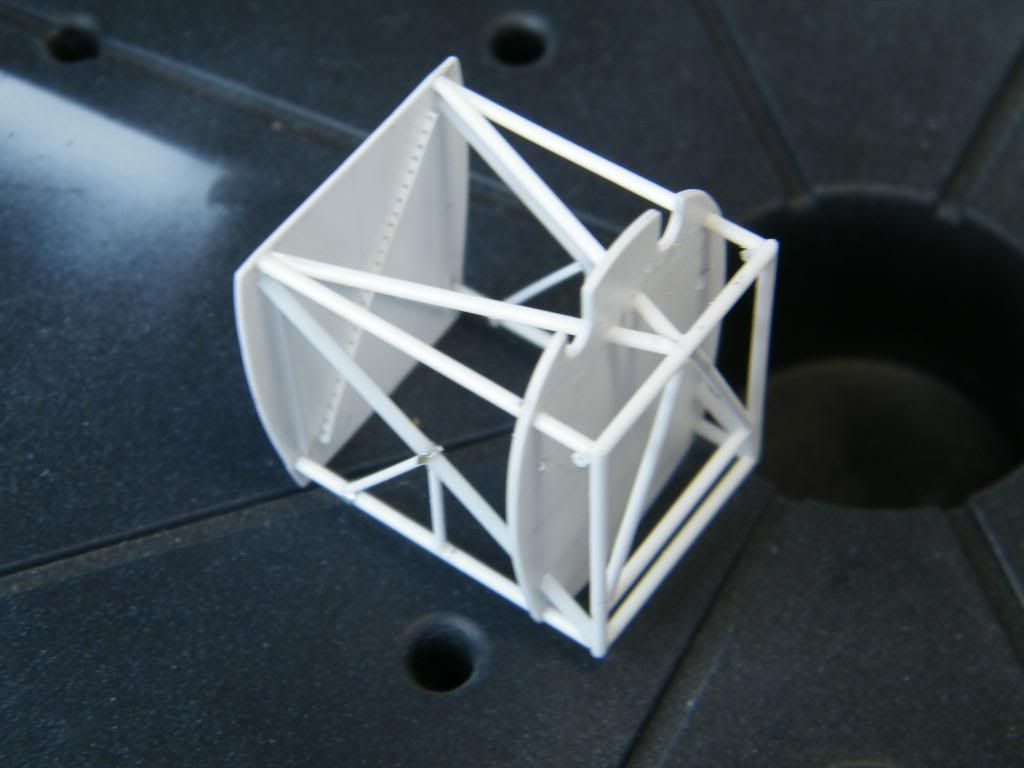
That is how I've started constructing maybe the most difficult part of my project.
Regards, Tomasz.
-
and fast as a lightning!!!
Thanks Thomas.
-
Hi everybody after break!
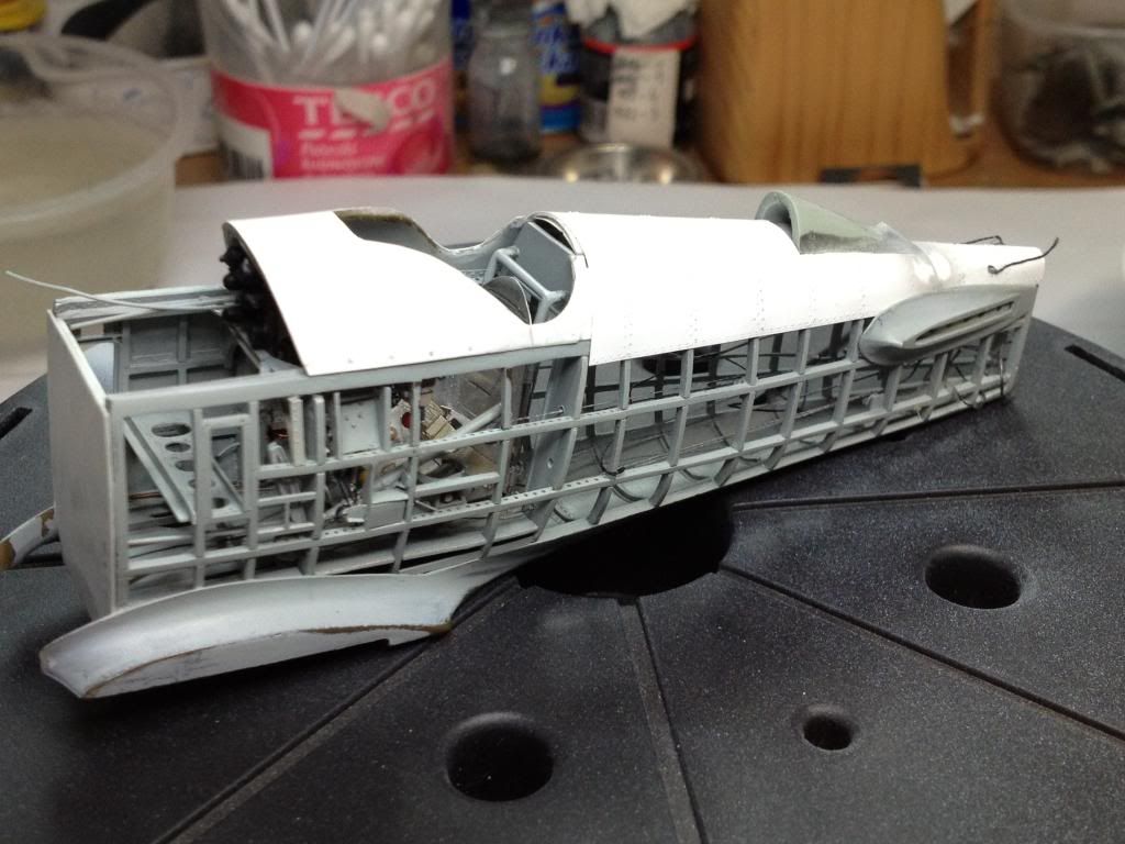
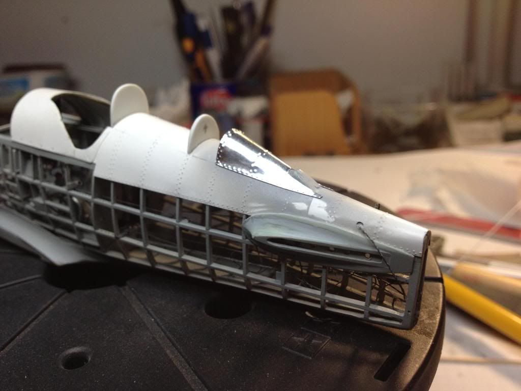
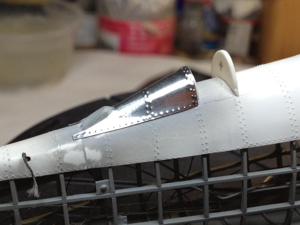
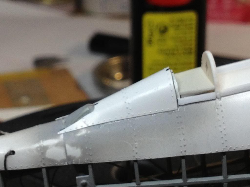
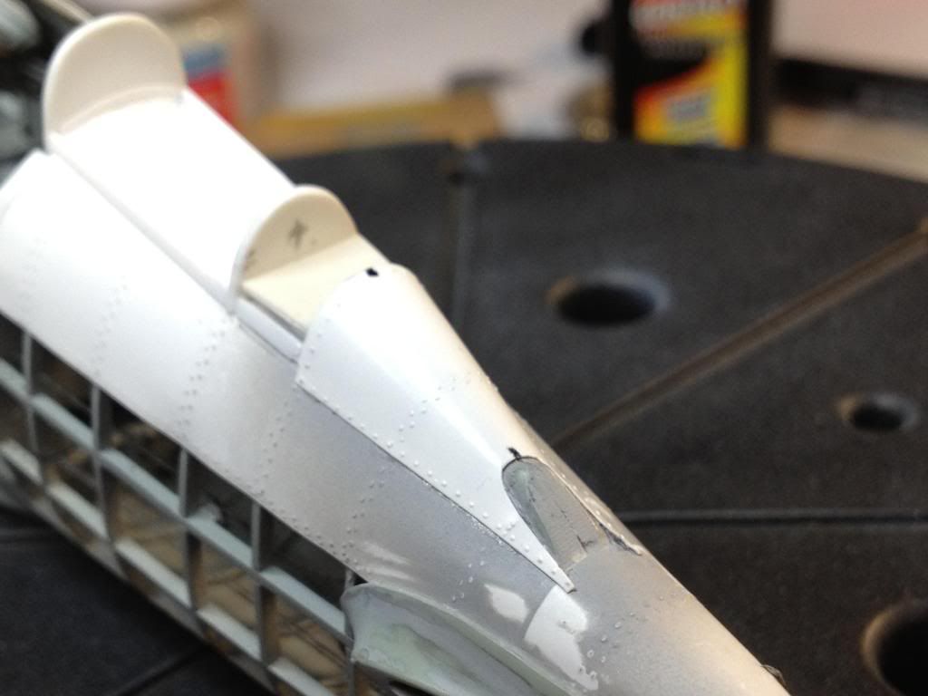
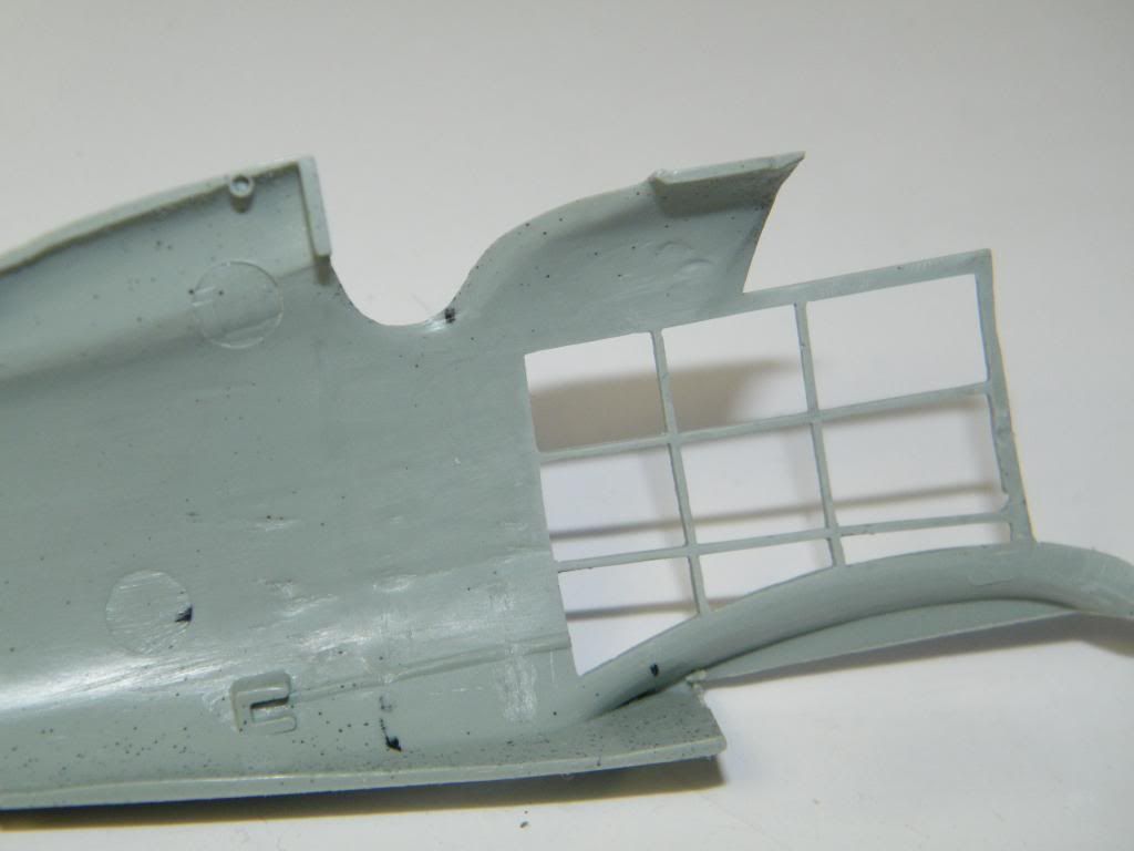
I decided to close front part of the cockpit making cockpit bulkead.
Next step- to creat new skin. I started from the cockpit.
You can see closed upper part of fuselage just behind the cockpit on two last photos. I made double skin, the inner one the same way as bottom earlier to creat frames and rivets inside of the fuselage.
Tomasz
-
-
Hi everybody!
Thank you for such hot comments.
I'm glad that my project could be inspiration for someone.
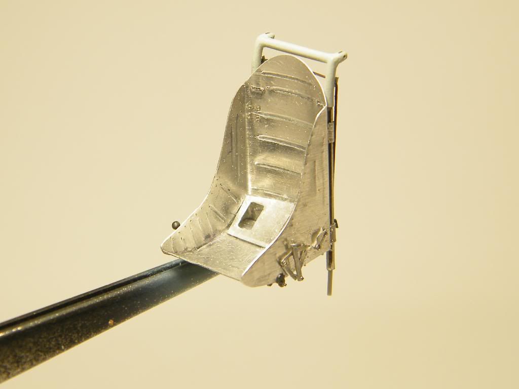
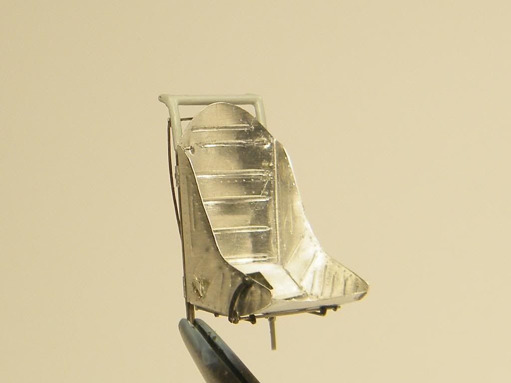
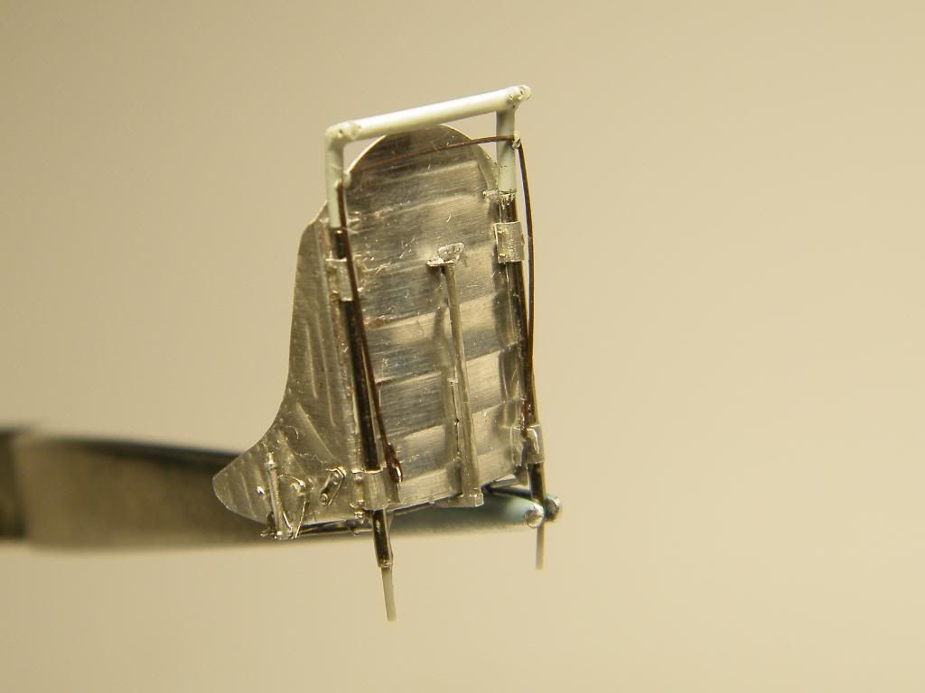
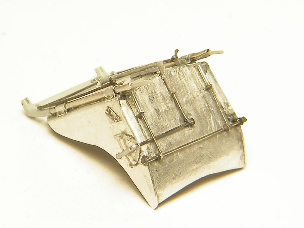
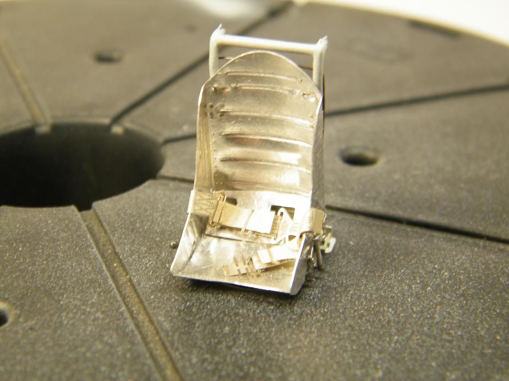
Fantastic work Tomaz - I am extremely impressed, especially your seat, which looks very like a Curtiss P-40 seat!
Derek
Yes, you are right. I couldn't find picture of all pilot seat, only small fragments. One of them compared to P 40 or P 38 seat. I chose last of them. I took one from Trumpeter kit and made test fitting. Dimensions were OK.
So i used it as a master. All detailes were made according photos.
I closed fuselage on the end of 2012. Good summary of the year.
Regards, Tomasz.
- Rdrunner, sandokan and Lars Befring
-
 3
3
-
Welcome!
You are all very kind. Your opinion are very motivated.
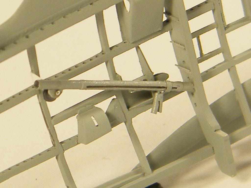
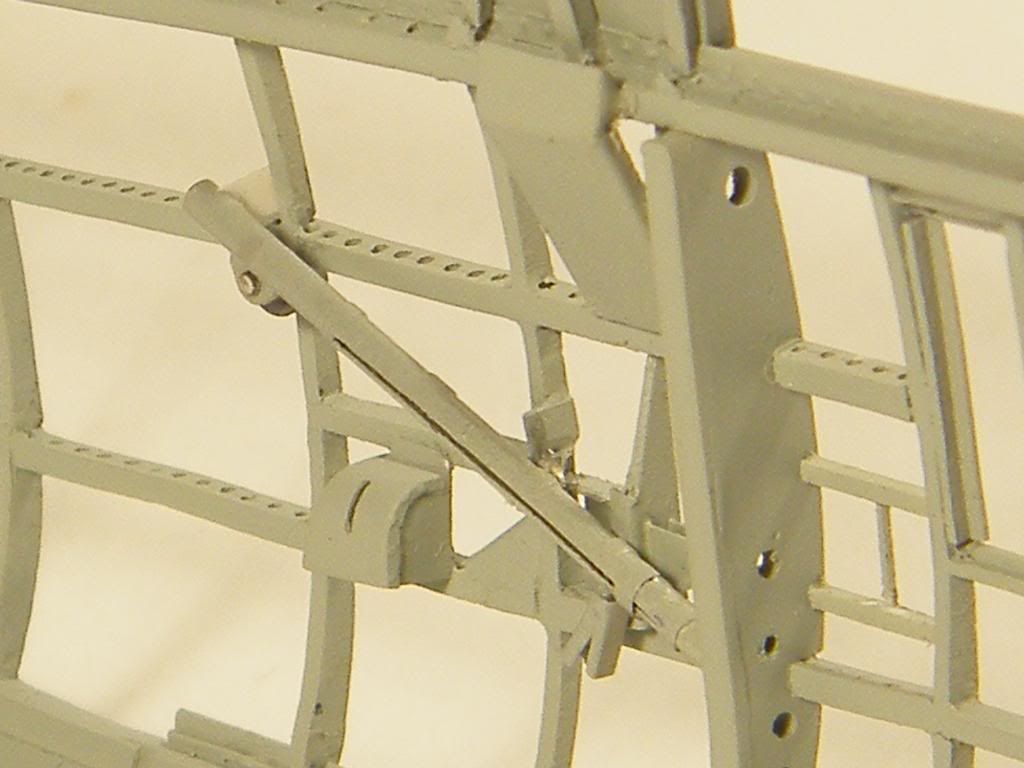
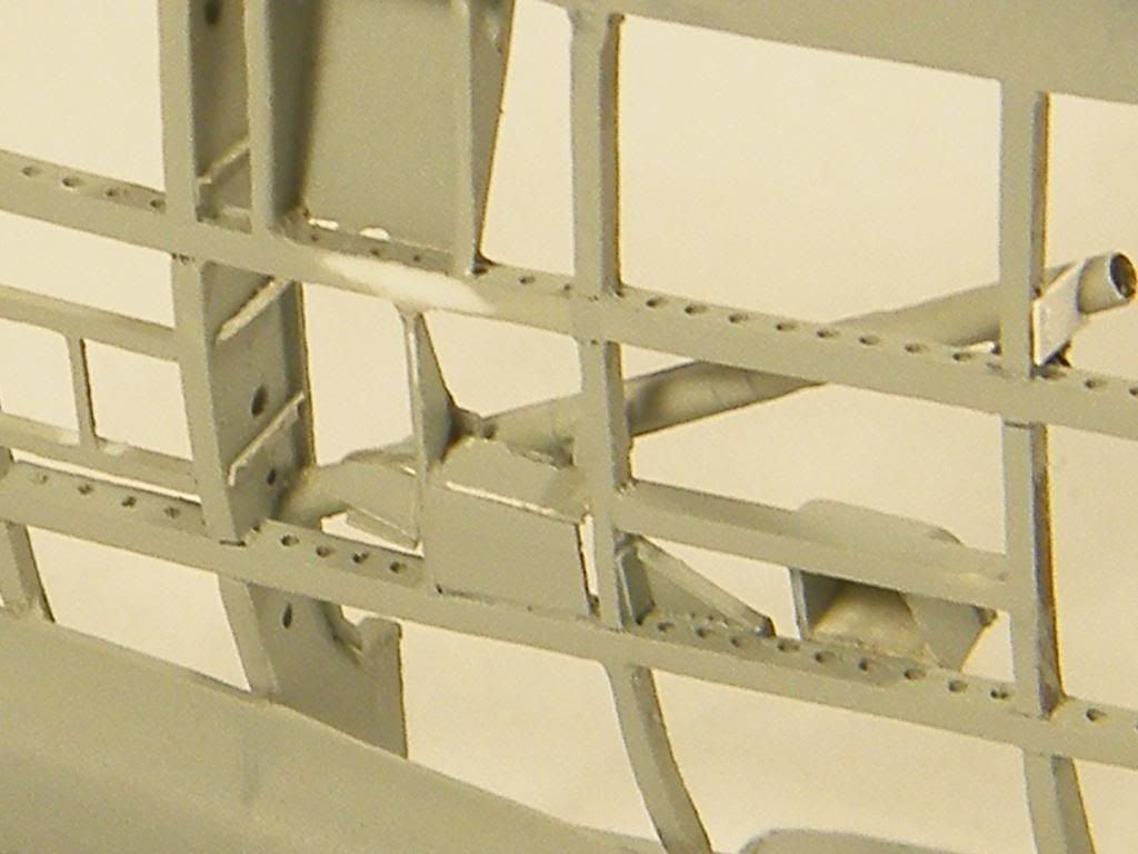
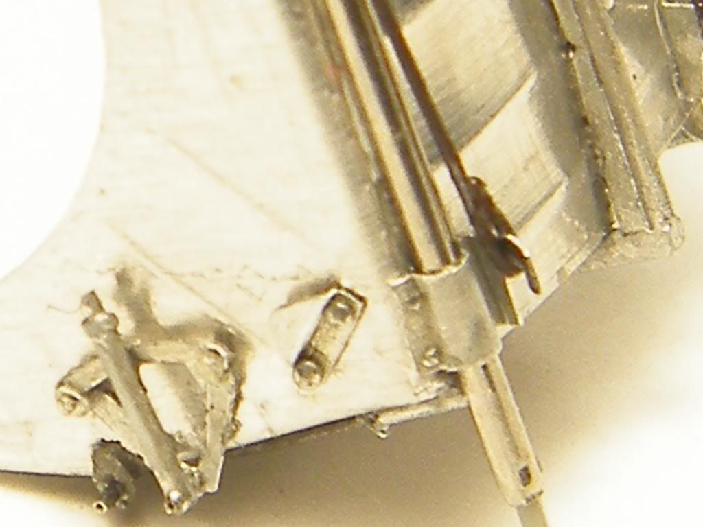
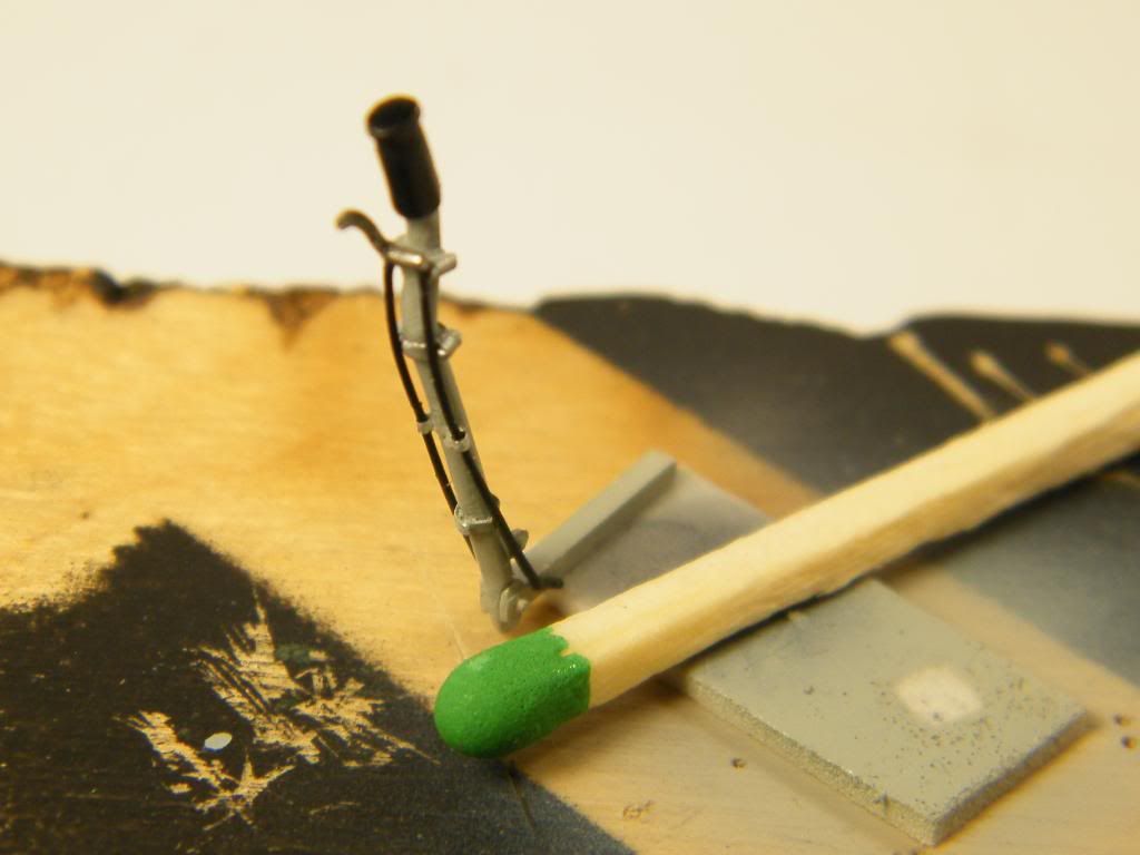
I'd like to describe how i made this strange, long tube. This is arrester hook control cable drive.
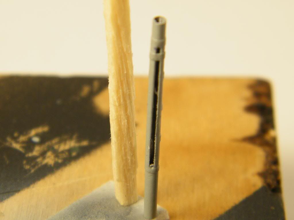
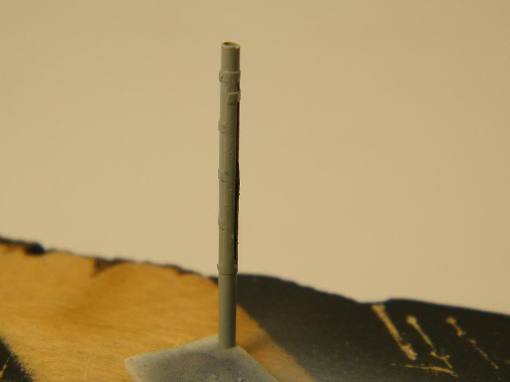
I rolled thin aluminium foil in tube. I put inside smooth part of drill the same diametr to make cut-out along the tube. I glued thin self adhesive foil outside the tube. On the end i put transparent stick inside to reinforce construction. Remember to paint the tube first, than put inside stick. I added some small details and that's all.
Of course, I made this detail in second attempt, first one in my opinion was to thick, about 0,15 mm in diameter.
Regards, Tomasz
-
-
I'd love a detailed 'how-to' on how you do a seat like that. That is A WORK OF ART. Would you consider doing such a how-to ? (do we have a place for that here on LSP?? It'll get buried on Tips and Techniques)
The idea how to do something is most important. I always try diffrent methodes, different materials. To figure out way to make something usually takes most time. So, be patient, don't affraid to start once again and try all methodes you discover. In this case as a material i used thin aluminium sheet. First i drew shape, rivet lines and places of overpress. I took pilot seat from trumpeter's lightning as a matter. I made overpresses using ballpen. I tried different tools like needle, toothpick, but ballpen was the best. i made overpresses, rivets first, than i cut out seat from sheet. Next i glued all together CA glue, and detailing, detailing .....
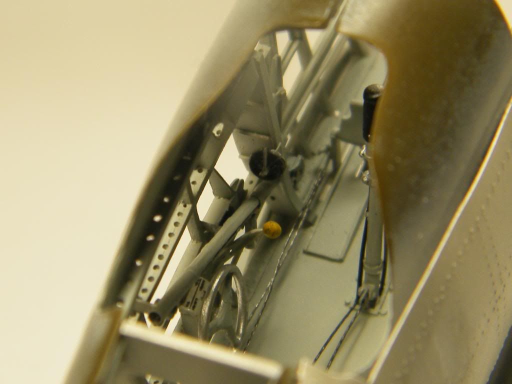
And now left side of the cockpit.
Original
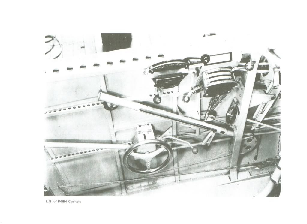
In this case all details have to look good from inside and outside because there is no skin on this area.
My attemptes
Regards, Tomasz.
- radial, sandokan and Lars Befring
-
3
-
Mind blowing !!
I never expected that my project could be dangerous.
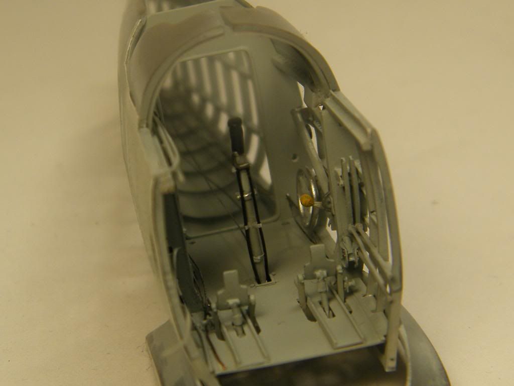
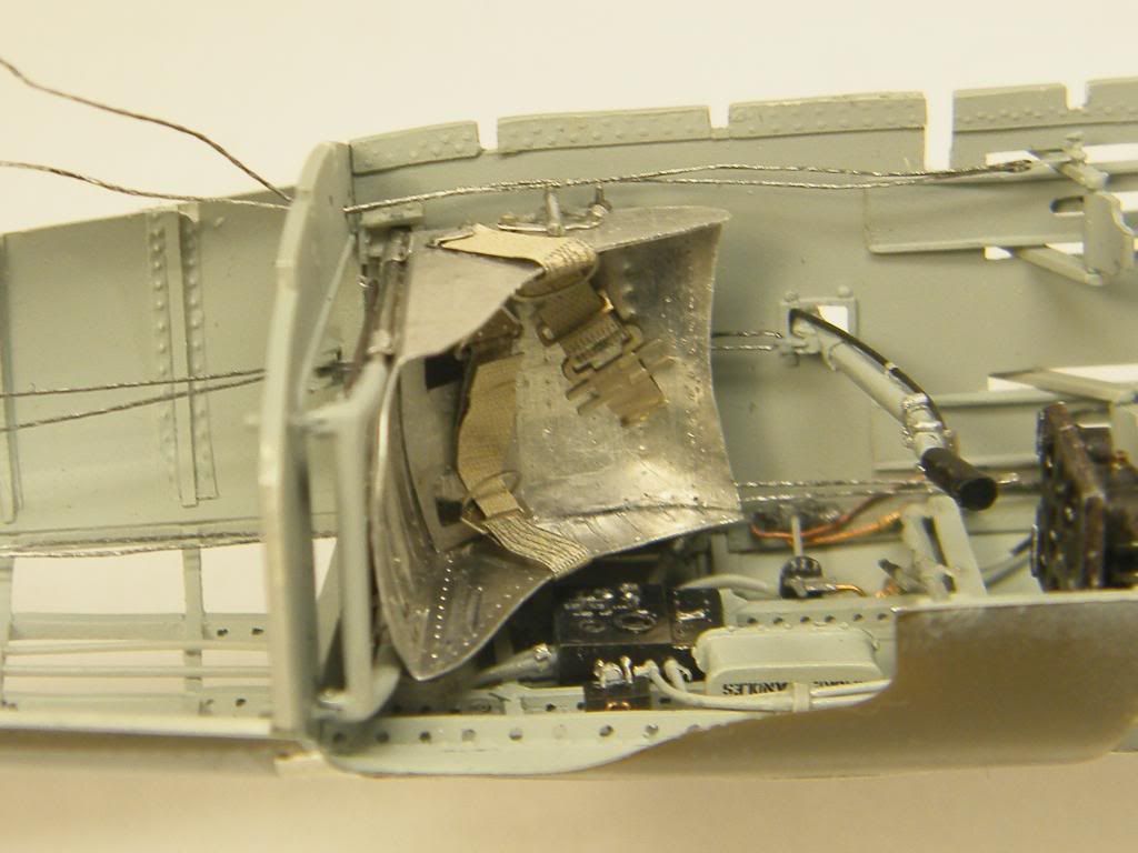
I showed pilot seat in the cockpit next time. I made it from thin aluminium sheet. First version was to wide (about 1 mmm) and i couldn't place it inside the cockpit when i put all together. Second one was correct.
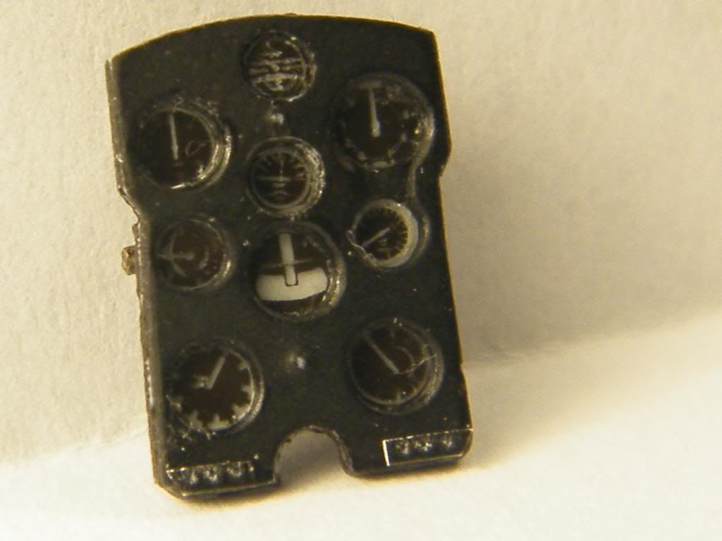
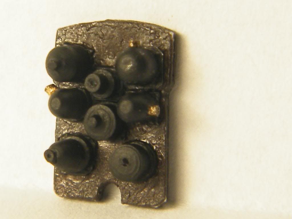
Instrument panel will be seen from both sides.
Regards,
and be carefull watching.
Tomasz
- sandokan and Lars Befring
-
2
-
Hi guys!
Tank you for your opinion
Very nice work. Are you going to do the wings the same way, or show off some yellow?
I plan to make left lower wing without fabric and some changes around stabilizers, fin and rudder.
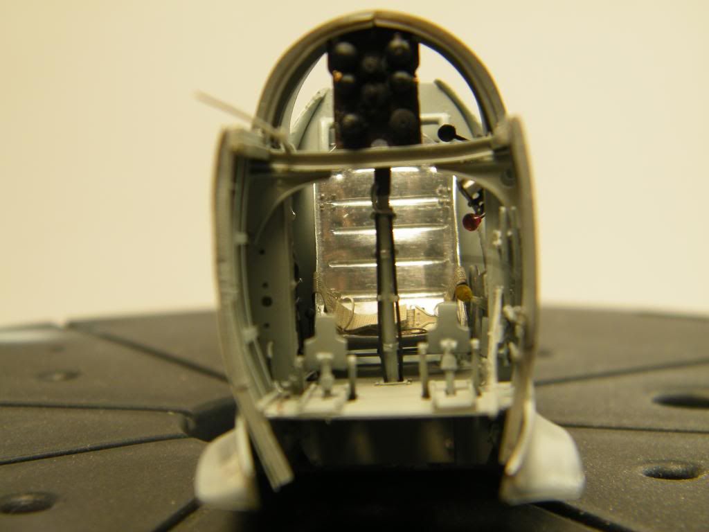
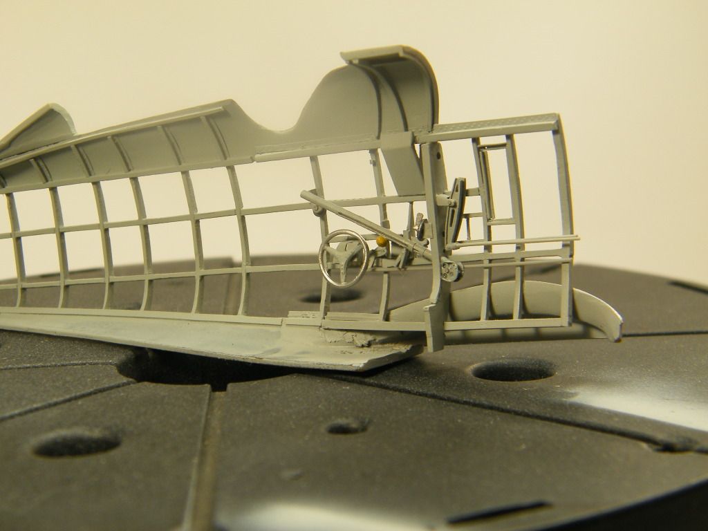
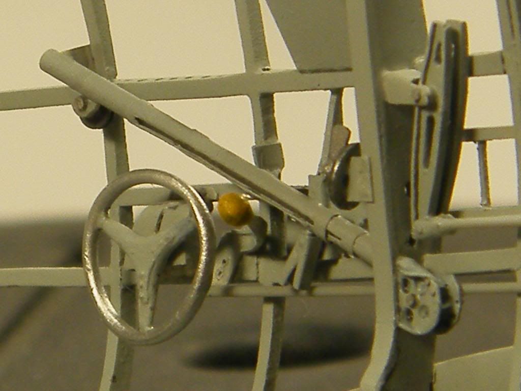
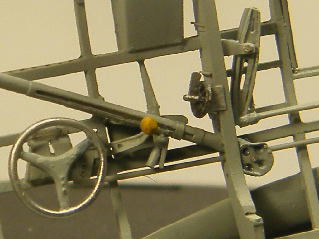
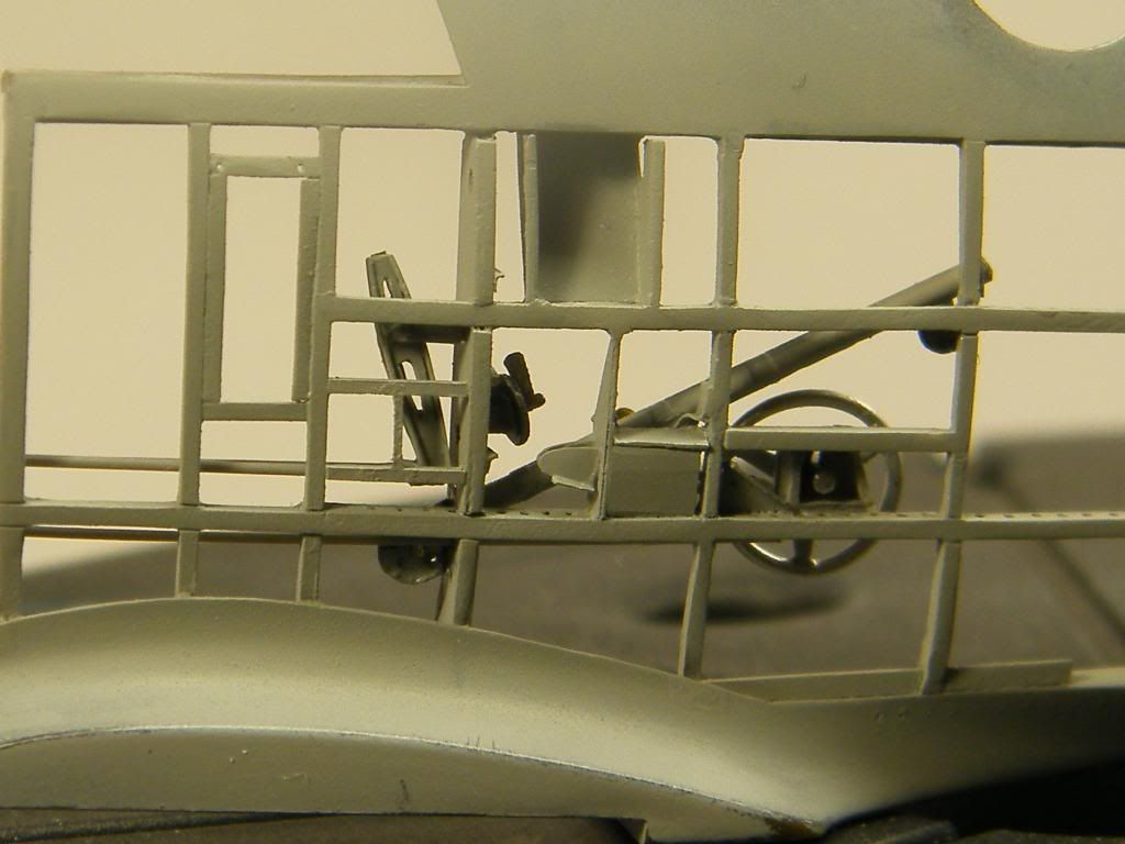
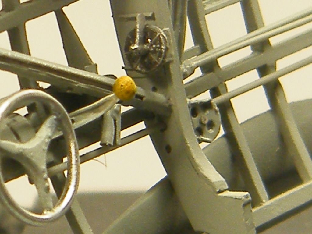
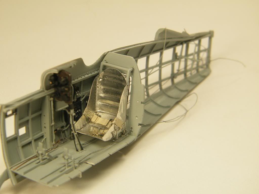
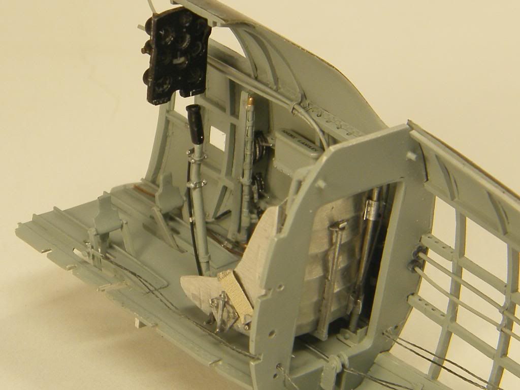
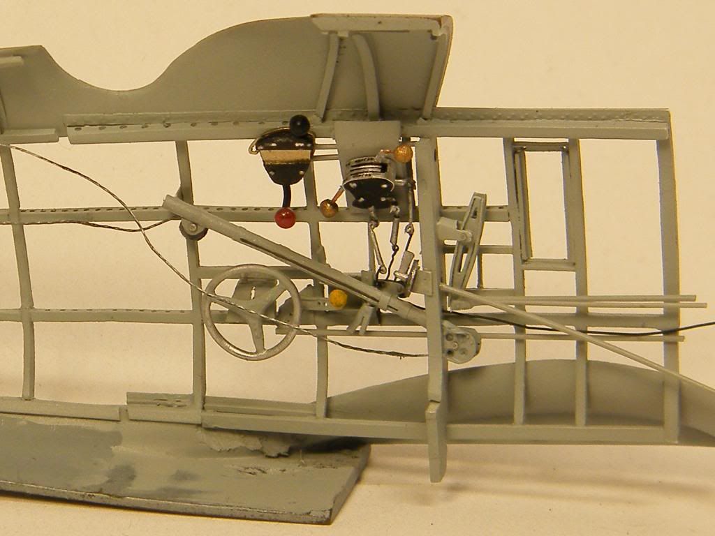
Some more details in the cockpit.
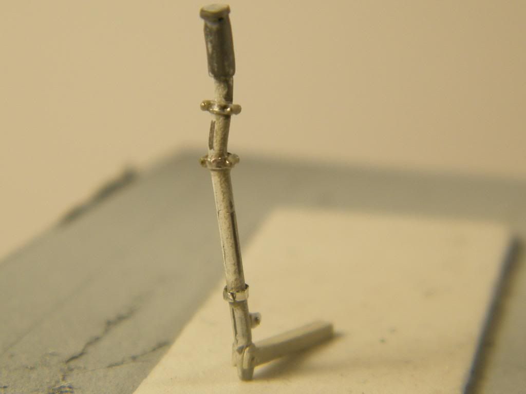
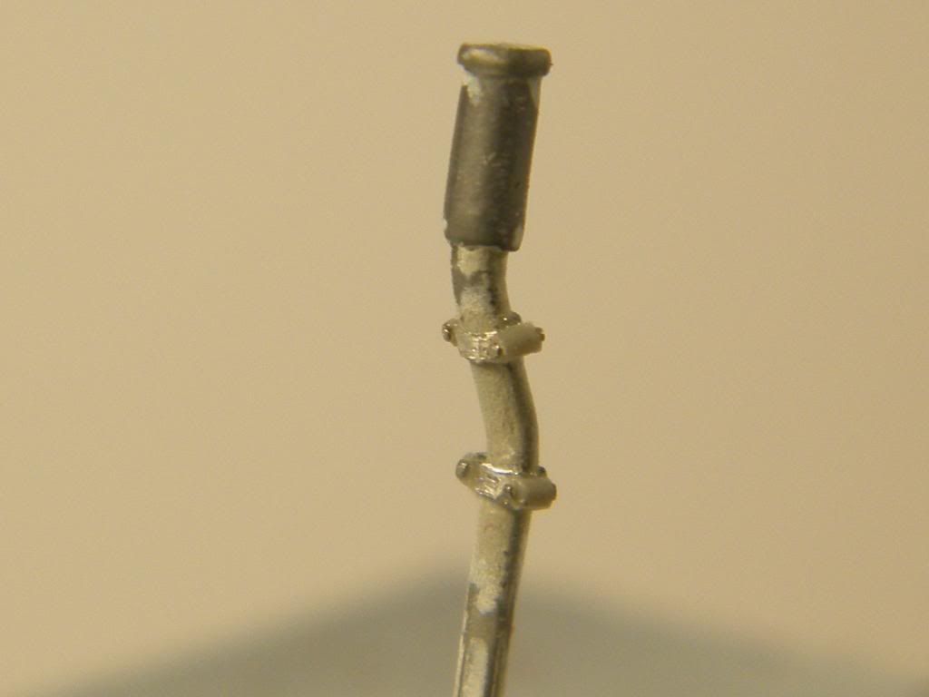
Control stick was reworked from kit part.
Rudder bar and pedals with wires.
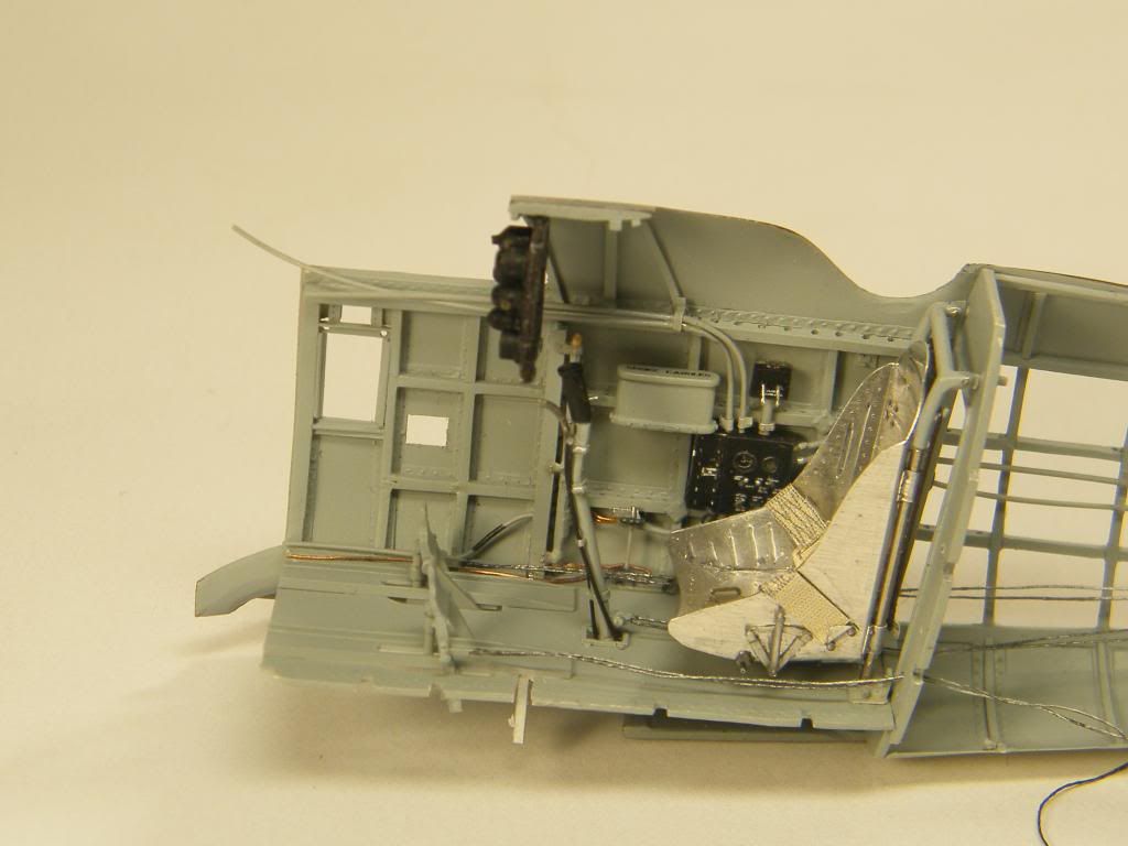
Starboard of the cockpit all together.
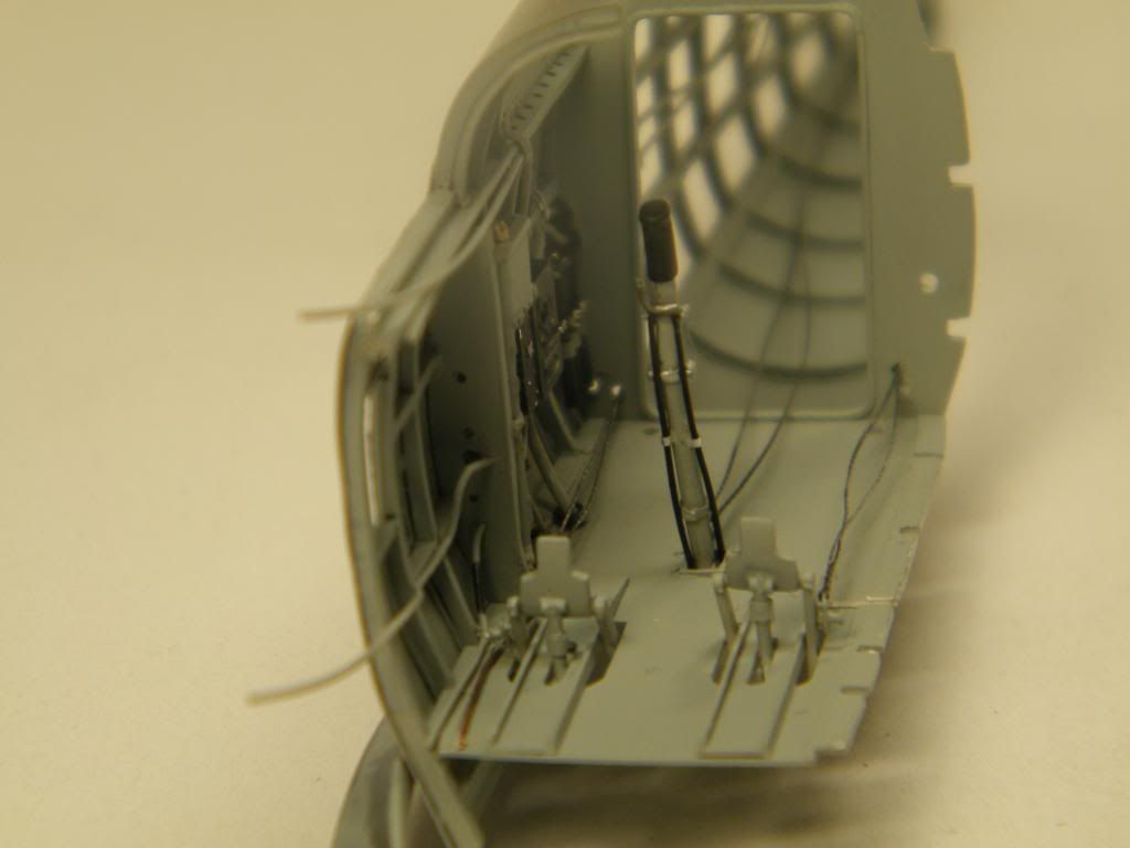
With pilot seat
Tomasz
-
Welcome on next part of the story.
Thanks for kind opinions.
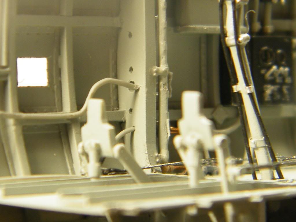
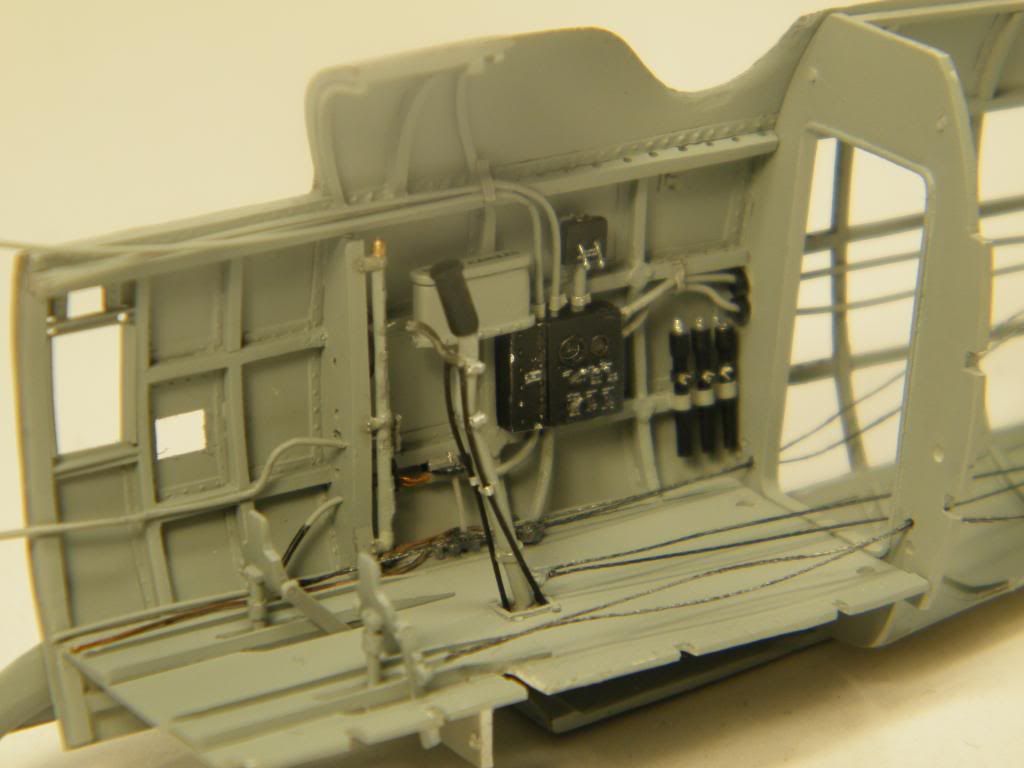
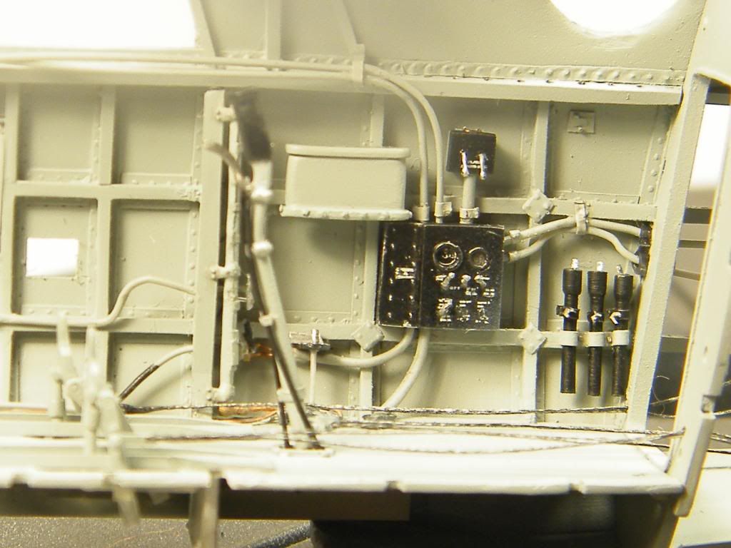
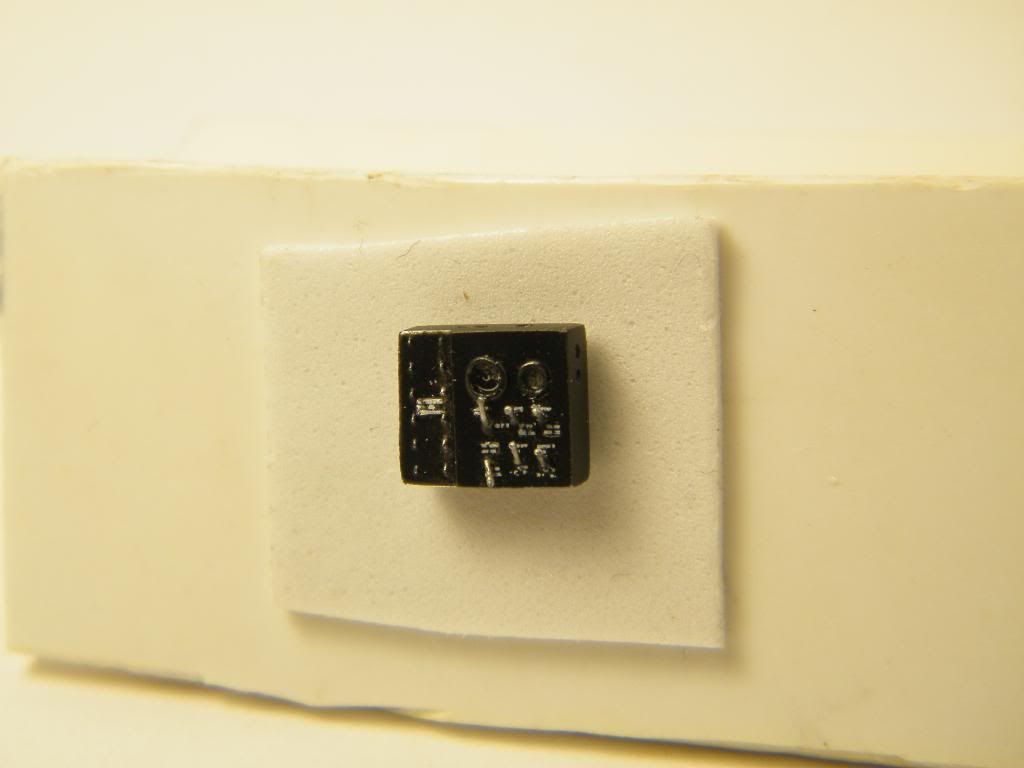
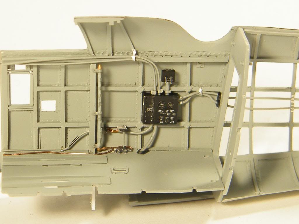
Something about detailing. First starboard of the cockpit. The aim.
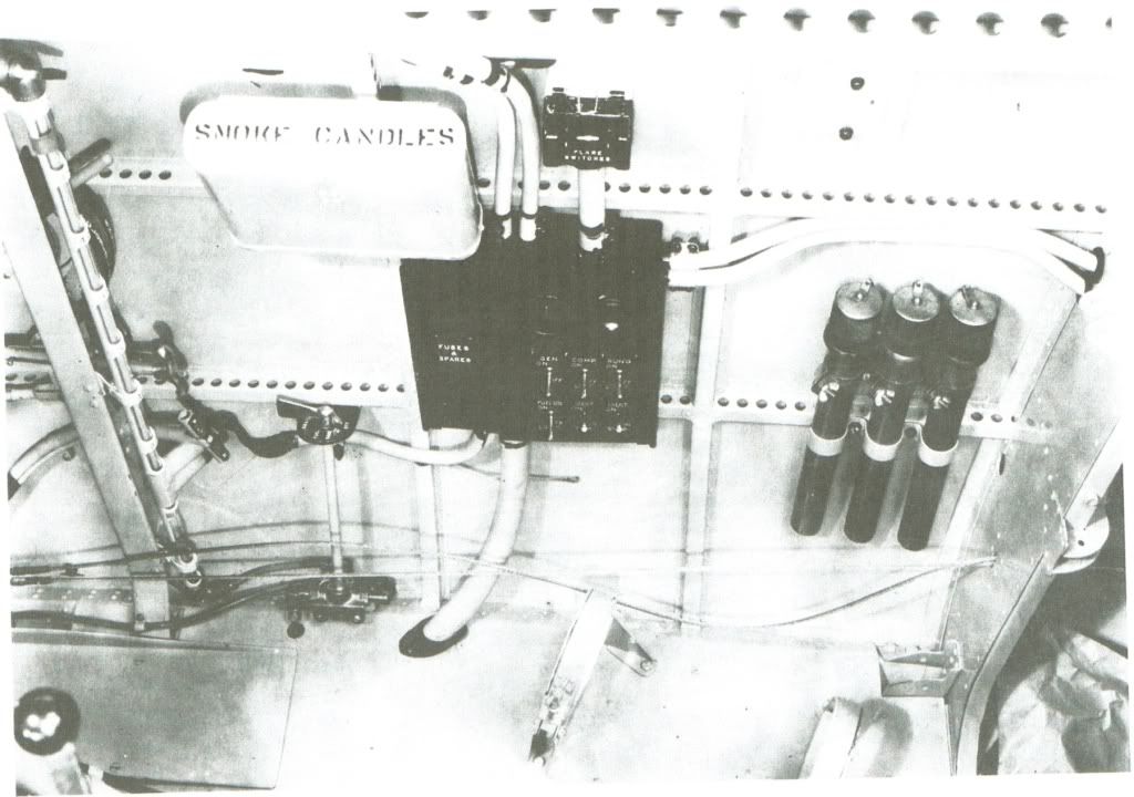
flares
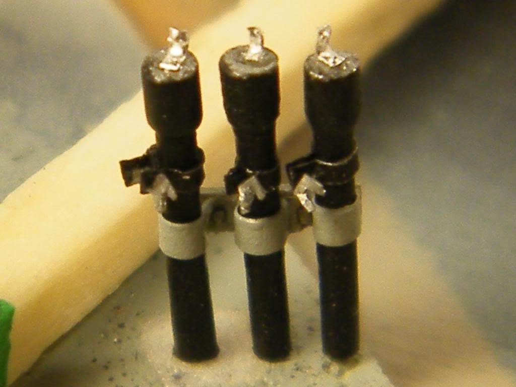
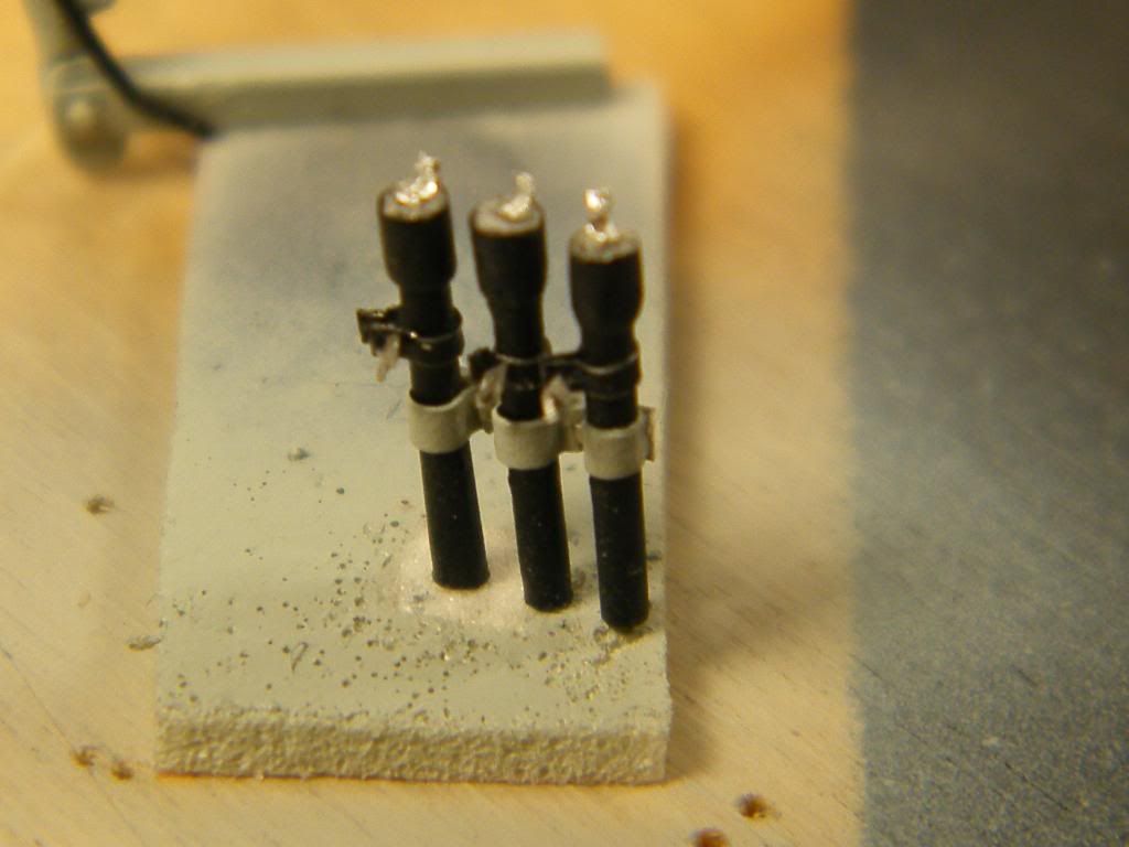
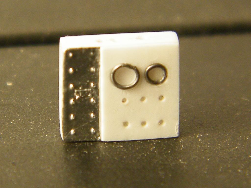
radio set
 [/url]
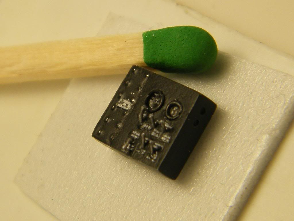 [/url]
[
 [/url]
With pipes, cables, valves
 [/url]
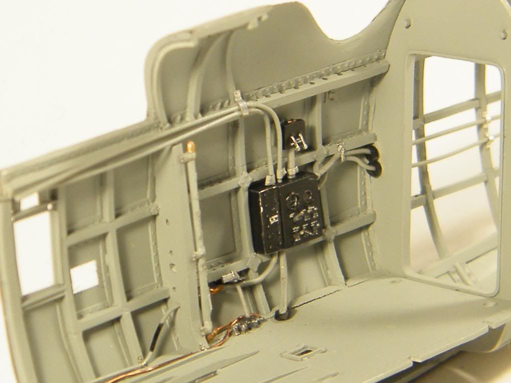 [/url]
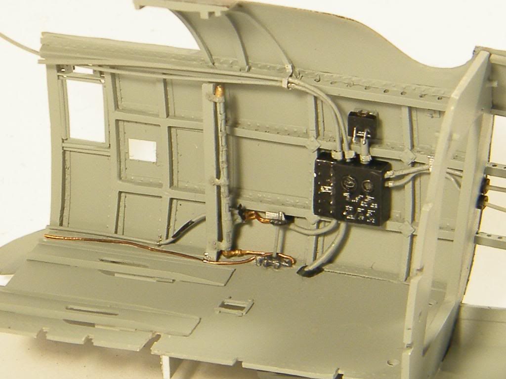 [/url]
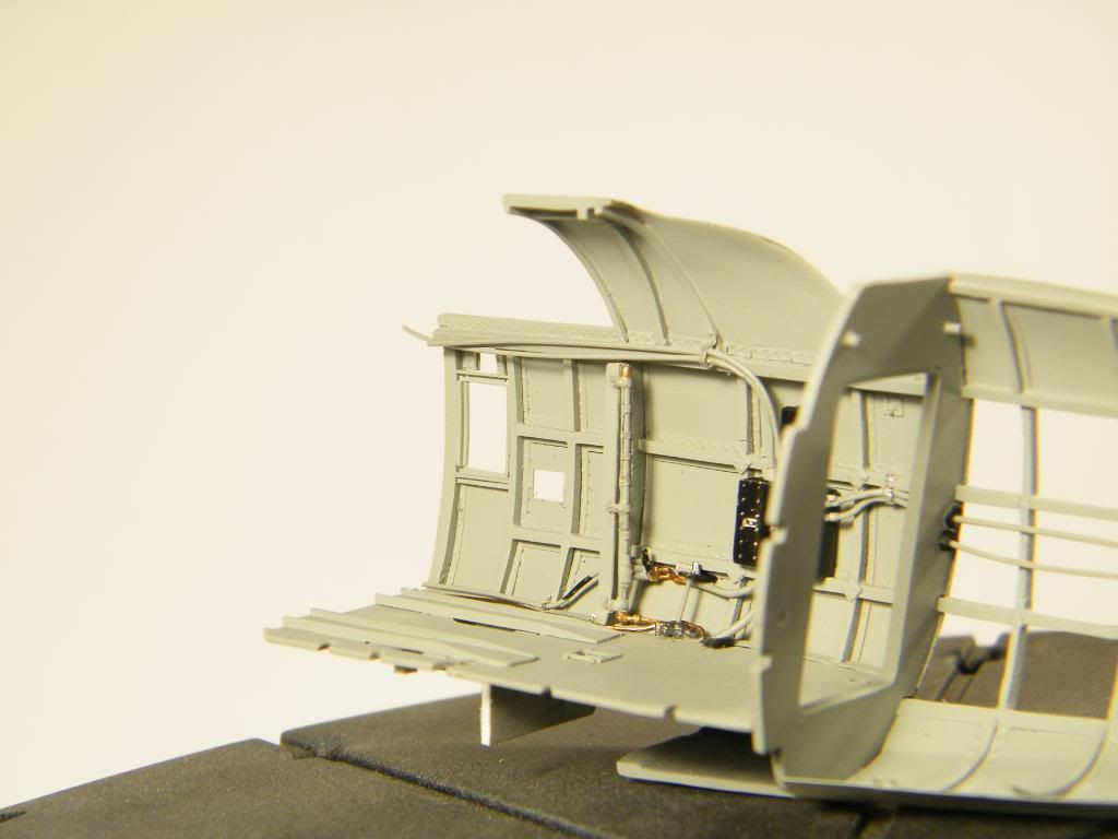
Almost every detail i had to make twice or even three times. First one was like a prototype, next better and last the best.
Regards.
Tomasz
- Lars Befring and sandokan
-
2
-
It is not my idea, I am only imitator. Andrzej Ziober, very good polish modeller, is the author of this method. He has built the model of Mi - 6 helicopter in 1/72 according this idea.He coaxed me into constructing my model the same way.Excellent idea, you know, this is going to be copied... Good ideas usually are..
-Al
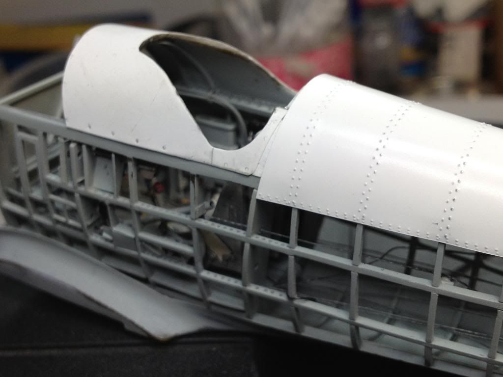
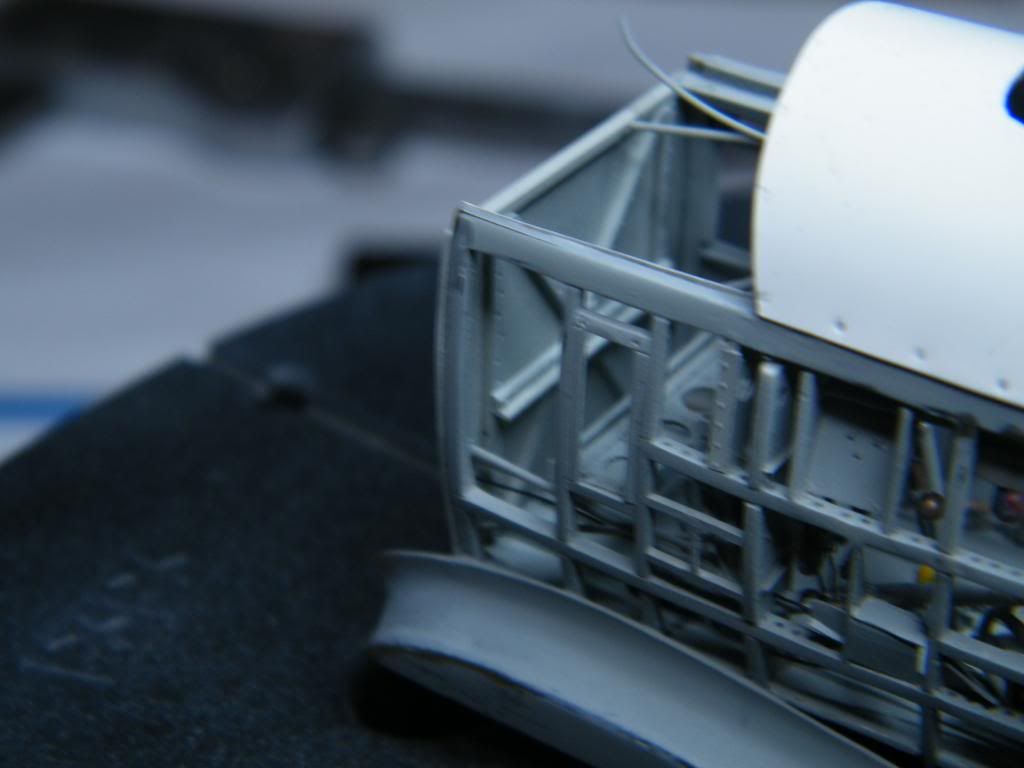
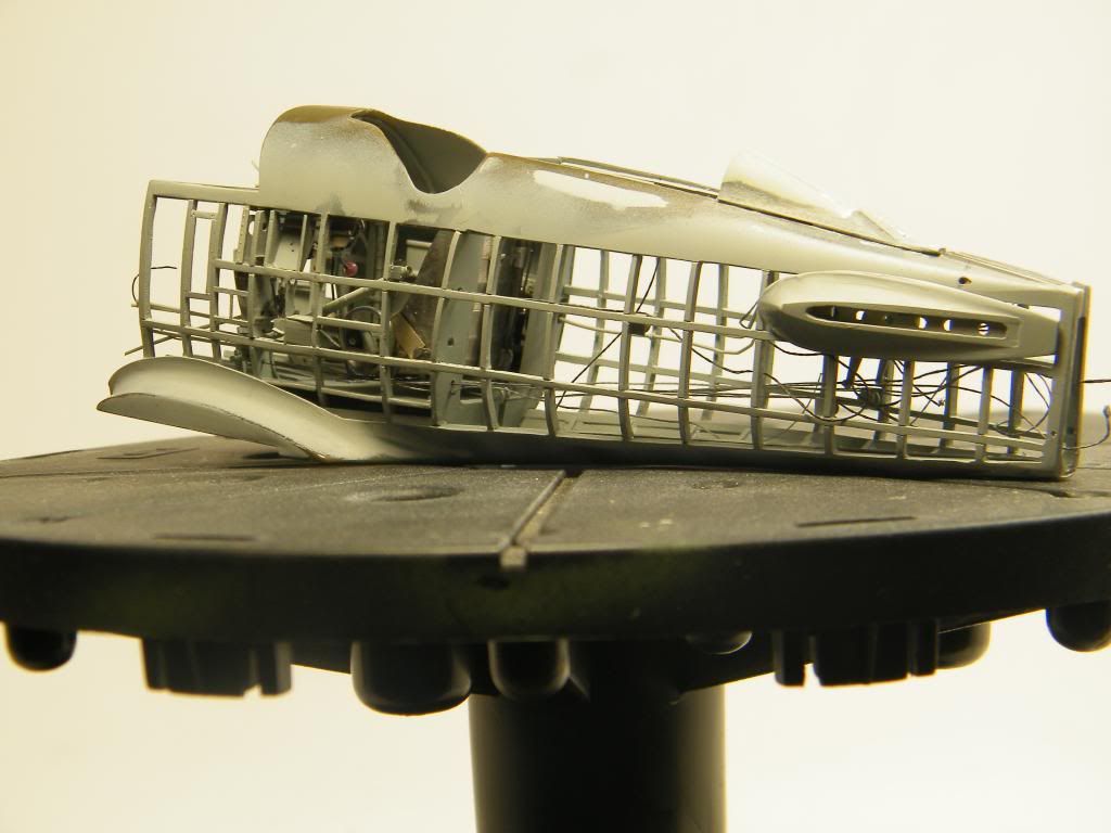
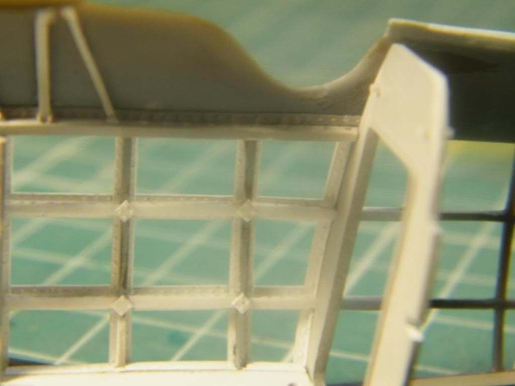
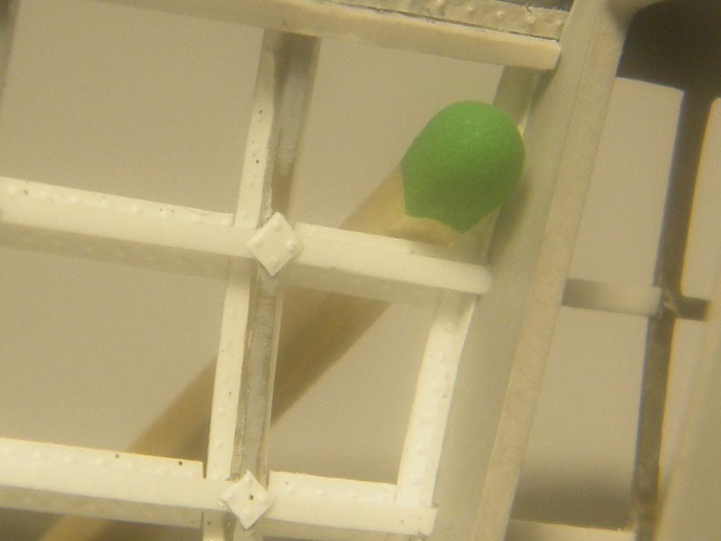
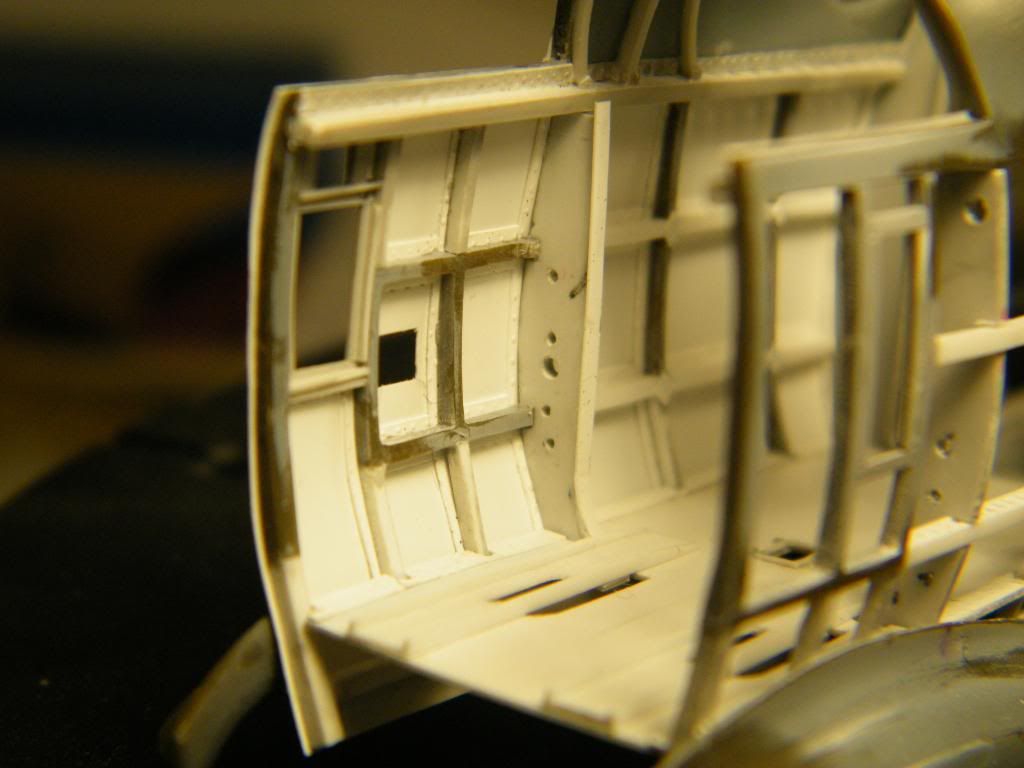
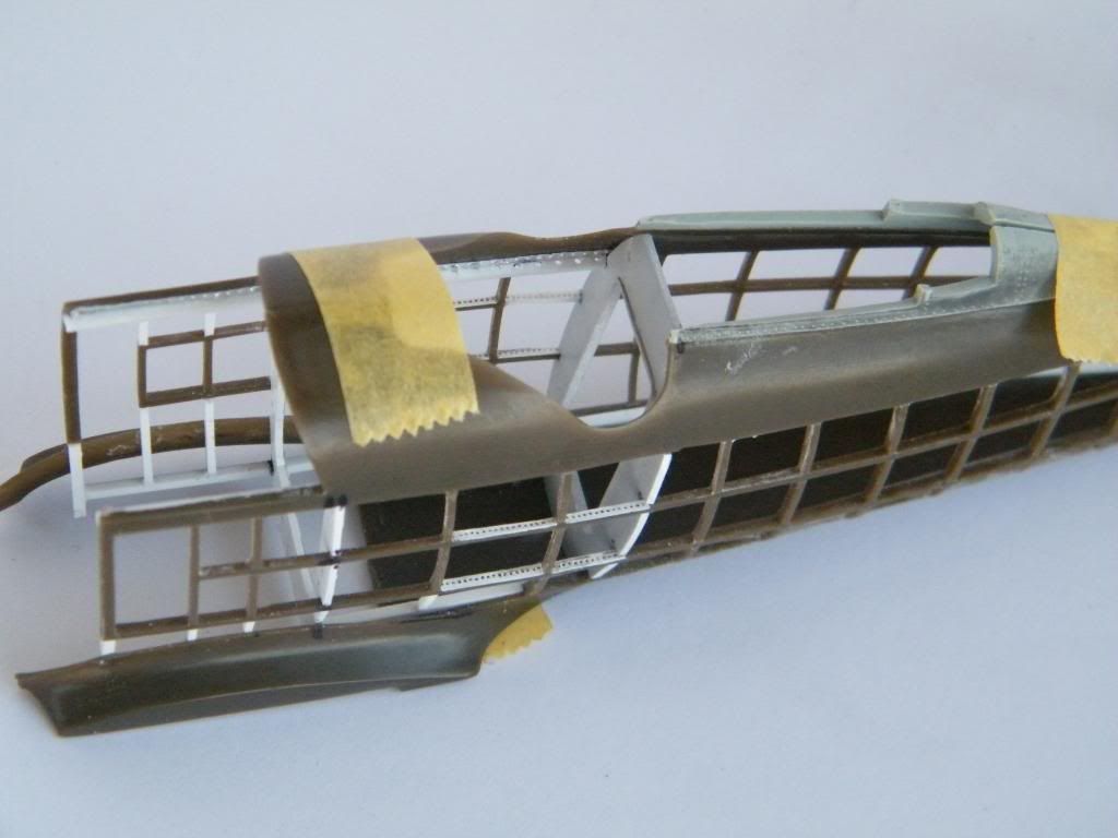
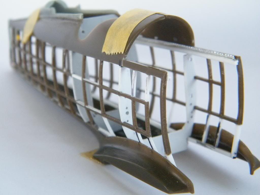
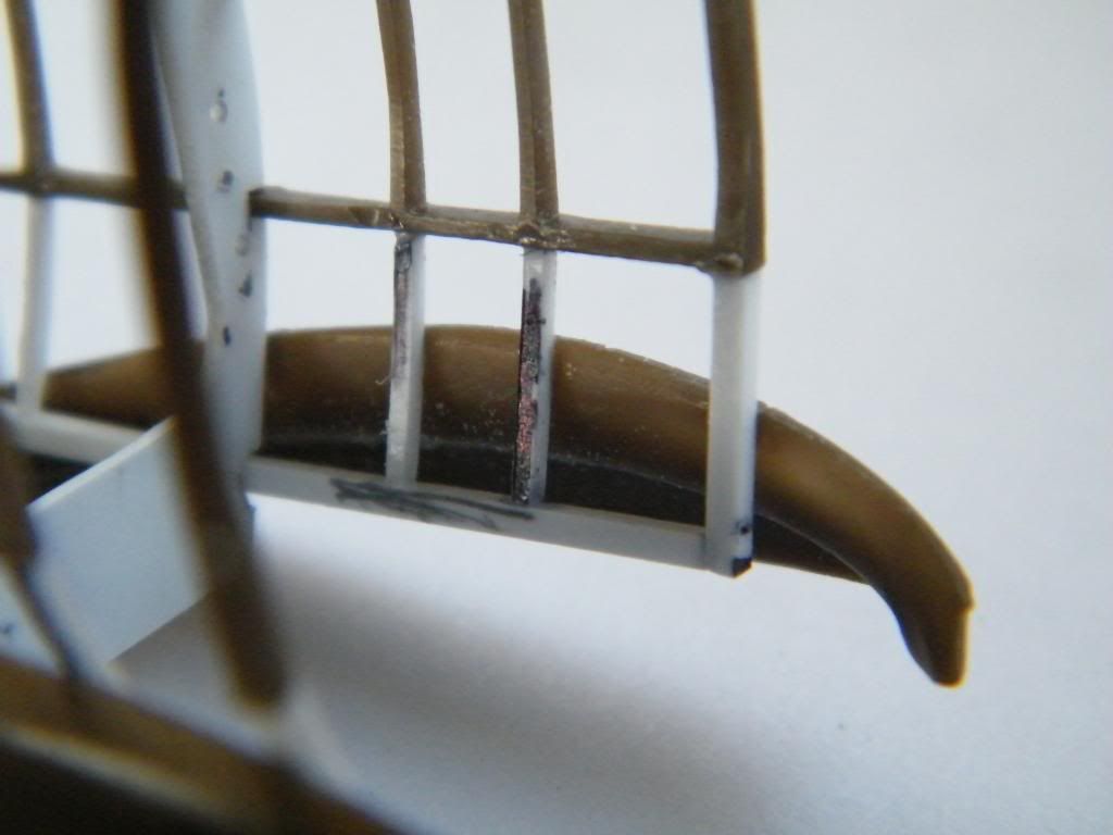
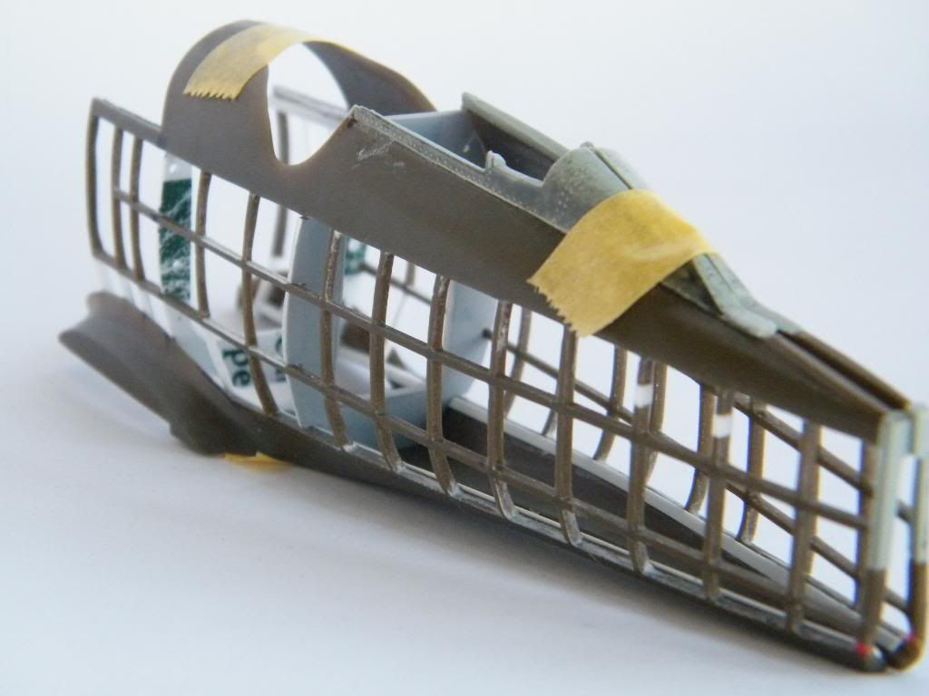
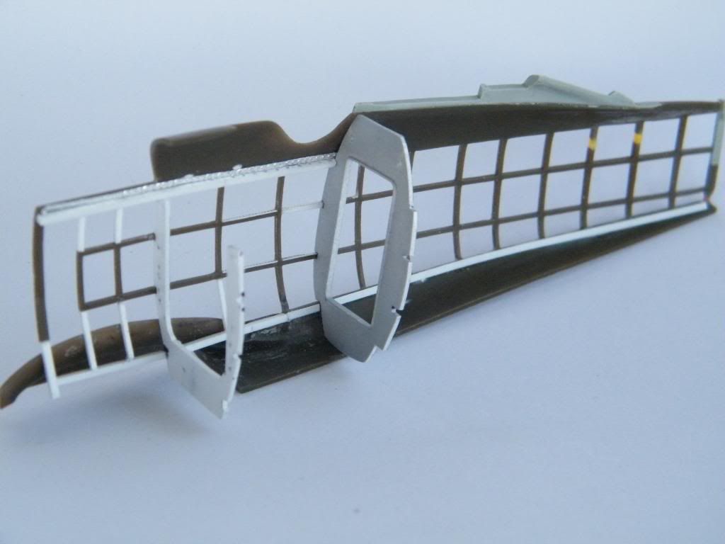
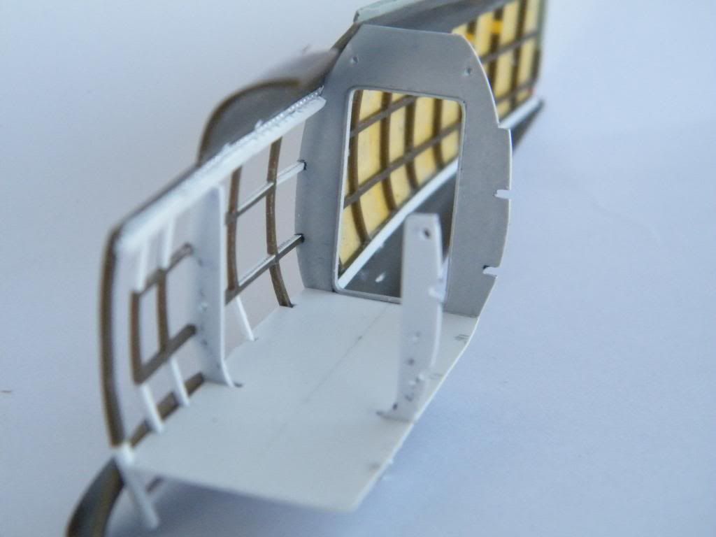
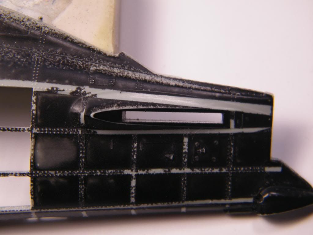
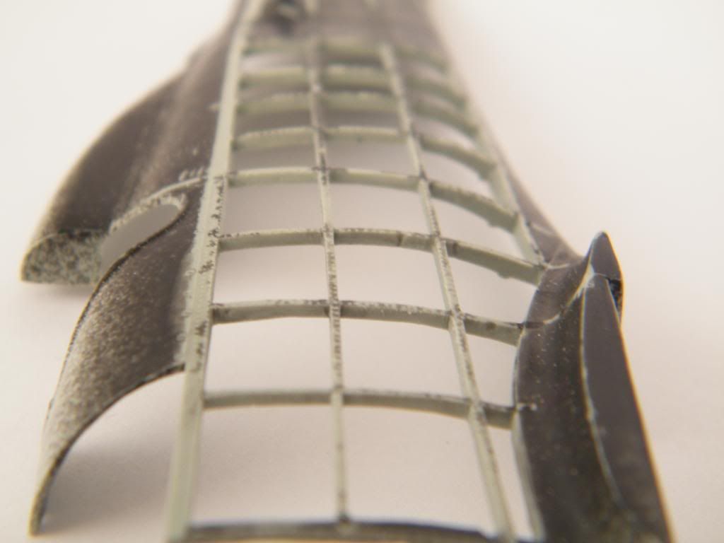
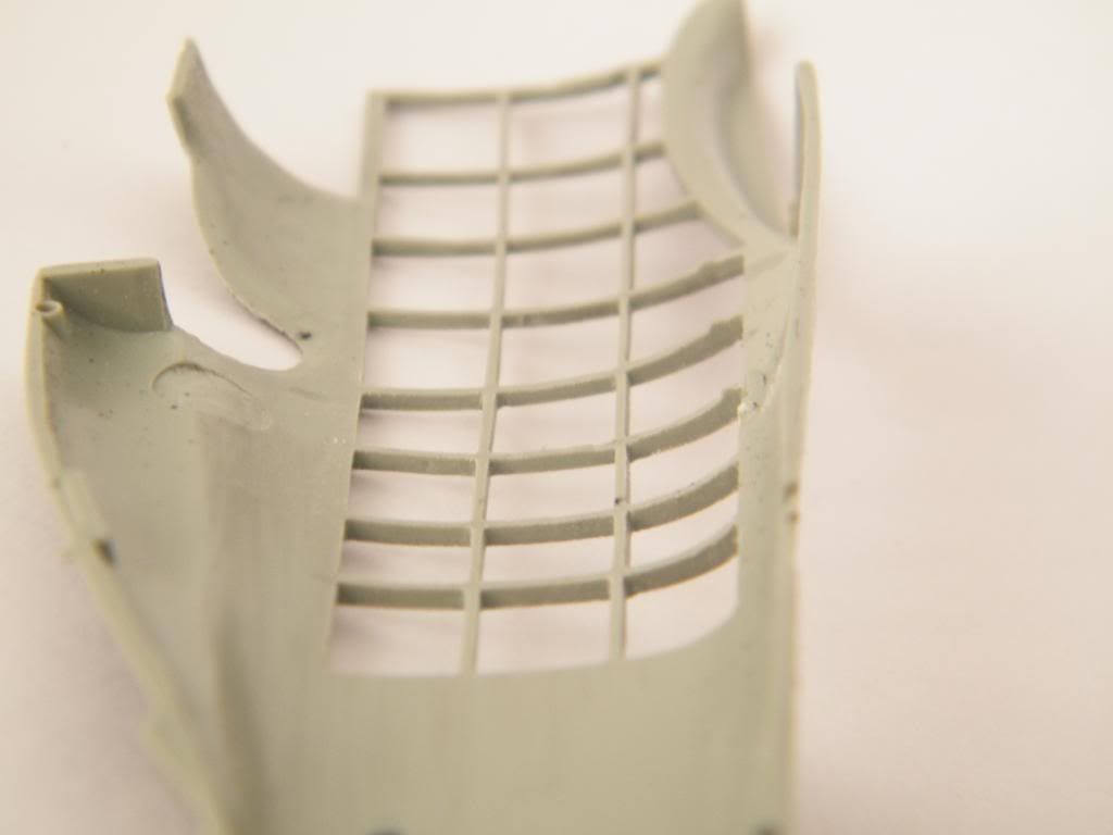
And now come back to my boieng. All interior is visible very well. I had to do frames and longerons inside, on the bottom and top of the fuselage. It could be difficult to do it after closing fuselage. So I made second skin with frames from the inside of the bottom.
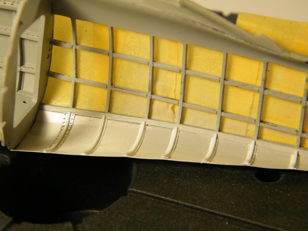
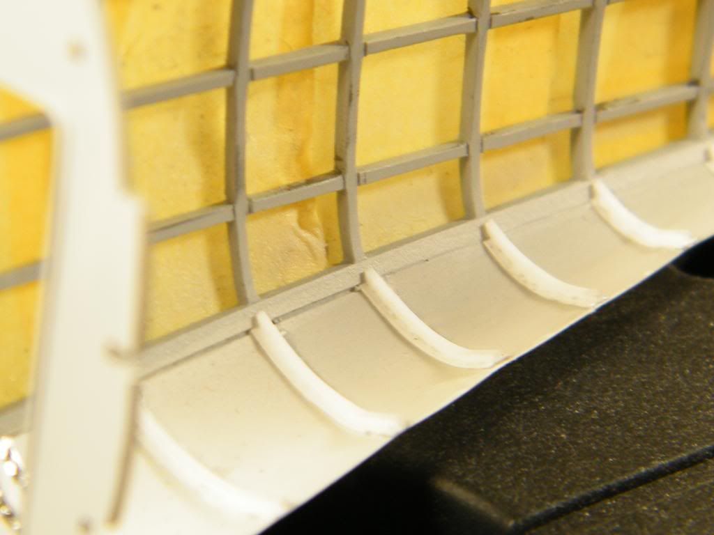
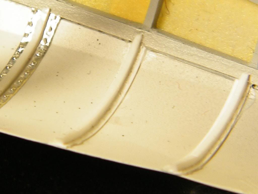
After adding top fragments of frames and longerons.
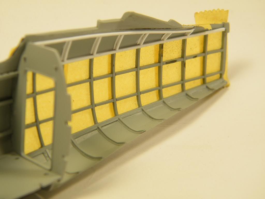
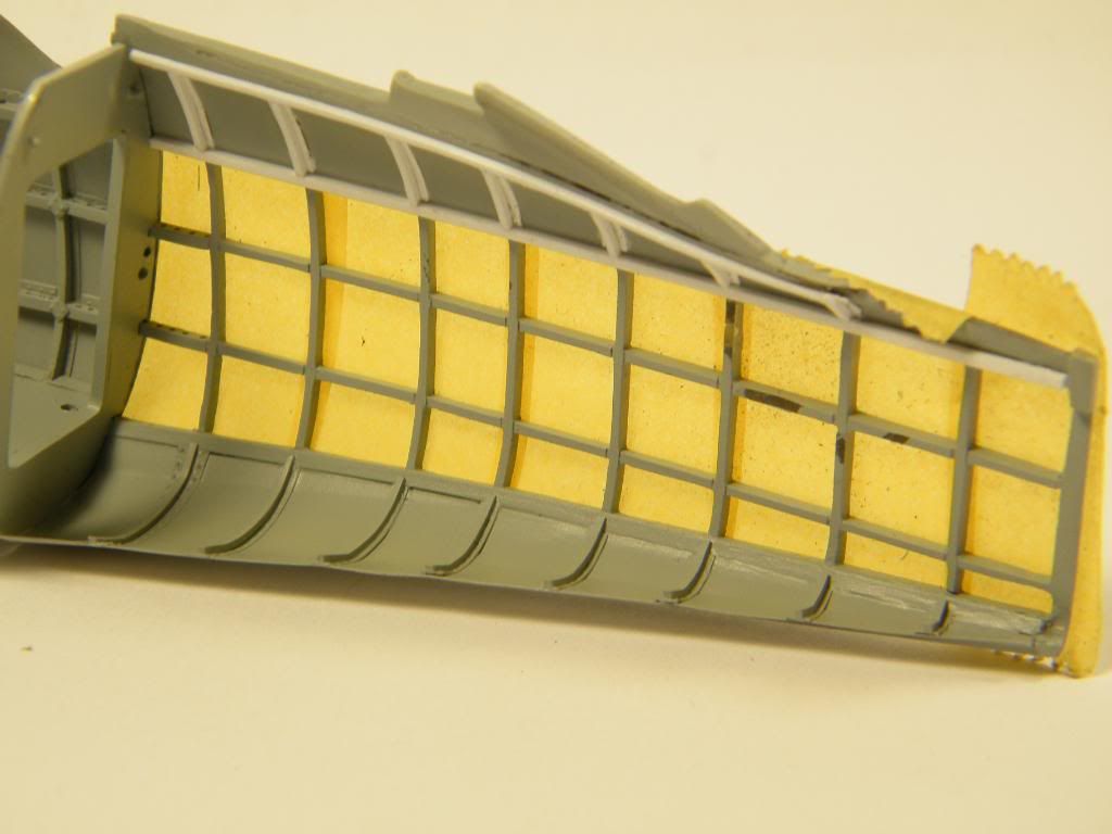
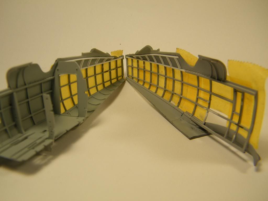
I use Tamiya tape to reinforce openwork fuselage and protect of breaking.
Regards, Tomasz.
-
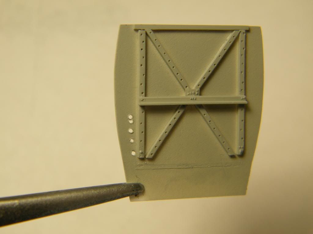
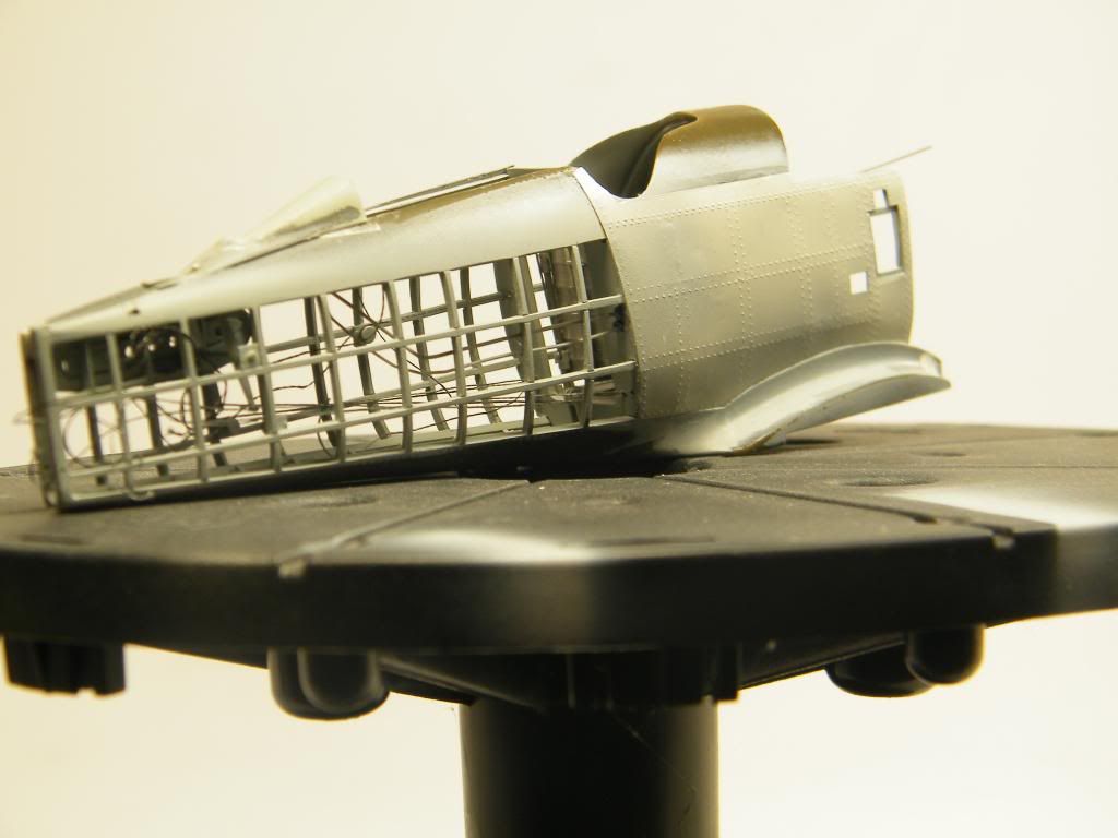
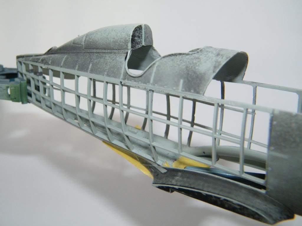
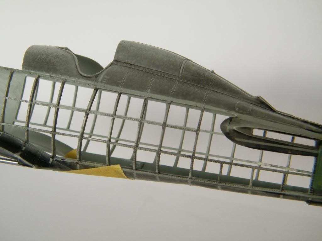
I decided to make the skin on starboard within the cockpit.I glued fasten flats with rivets to construction first.
i cut off the skin from thin plastic and made rivet lines from inside using riveting tool. I glued it together with thin Tamiya cement.
See you next time.
Tomasz
- Squizzy 78, sandokan, TonyT and 1 other
-
4
-
I've got a question about life raft stowage, just behind the cockpit, espacially it's cover. Is this in one piece, or consist of two pieces, opened on both sides, on hinges. My be someone could help me in this subject?
I 've just discovered wonderfull walkaround my boeing on this forum, but i doubt if this plane is original. I found differences with original photos in some areas. So, do you know something about this aircraft?
A few words about situation after the accident. I decided to start once more. I could cut off all frames and longerones better and faster. I didn't have f4b4 set, so i took P12. I had to make longer fuselage and change the ridge.
I bought new f4b in the meantime. I need more than one set for such project, god bless it's not expensive. Some photos.
Hasegawa kit was only pretekst to build this model. All the rest - scratch. So i made two main frames in the cockpit and cockpit floor.
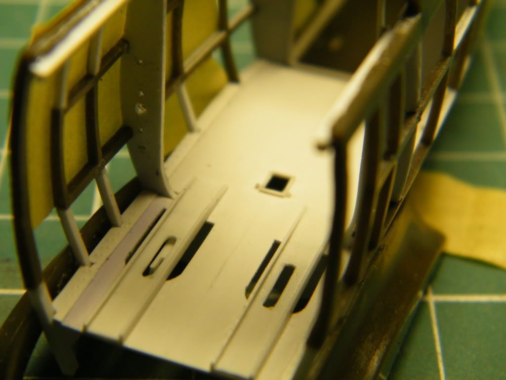
Regards, Tomasz.
-
Cześć Tomku,
I am very glad that you showed here the progress of the construction of your great Boeing

Thank you, Krzysiek.
It was your suggestion.
Thanks all.
Next parts of my project soon.
Regards, Tomasz.
-
Hi everybody!
I had often visited this forum and always admired wonderful constructions that were presented there. And now I have decided to share my own project with you. I come from Poland, but I decided to build one of the American biplanes from the interwar period. Why did I choose a plane without an interesting history? No offend intended. In my opinion it has a great potential for a very interesting model-making project. I started to build it two years ago and I am still working on it. In several posts I would like to describe all my efforts to this moment.
I think you all know what does Boeing F4b4 from Hasegawa mean. It is almost a toy.
I like to open my models and do something that was not done before. Or maybe I simply didn't see anything done like that.
So in this project I decided to open some areas of the fuselage but after discussing it with my friend Andrzej Ziober I didn't need much persuading to do something more – almost full opened model with only small areas covered with skin. The thick sprues of the fuselage provoked me to cut off all the frame from both halves. So I marked lines of the frame and started cutting it out.
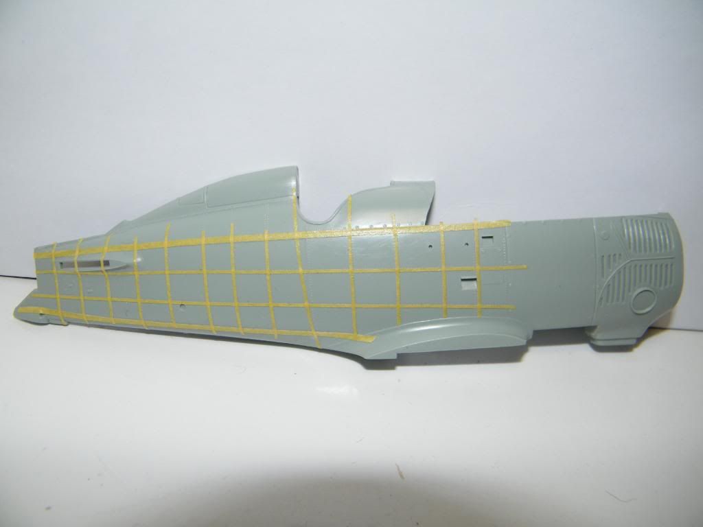
After a month of cutting the terrible accident happened. During polishing inside one of the halves the frame was broken.
But nobody said that the work would be nice and easy. In fact the accident appeared to be the blessing for my work. The main difficulty for me was an insufficient documentation - especially good drawings. The only support for this project were the pictures of original planes. I do not want to bore you to death so I think that would be enough for the first time.
Tomasz


1/32 Boeing F4b4 - almost naked
in Works in Progress
Posted
I have to think about it!!!
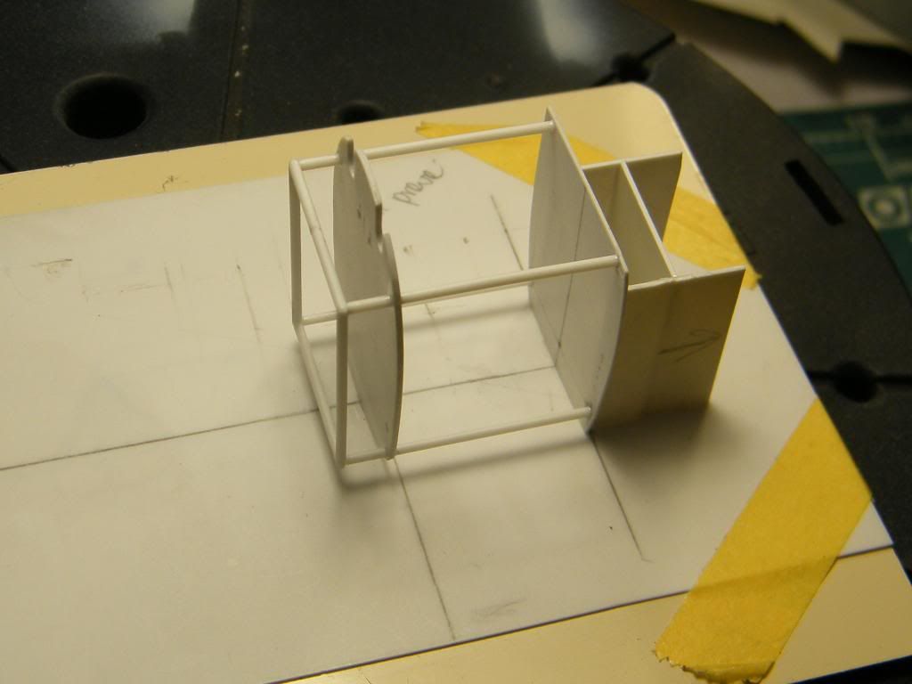
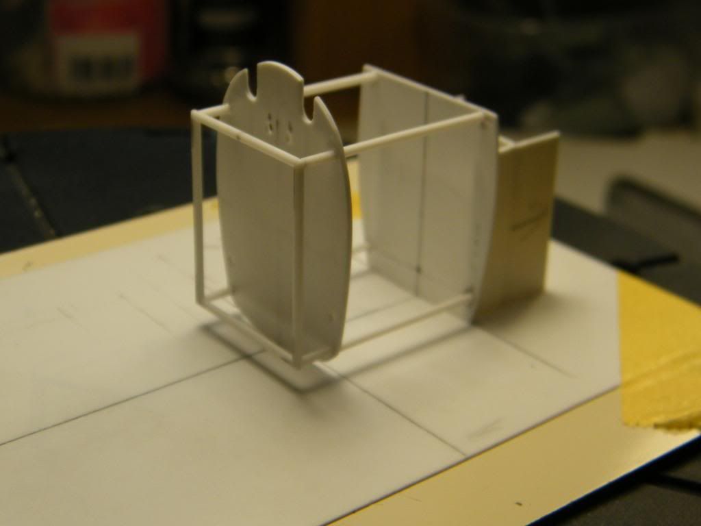
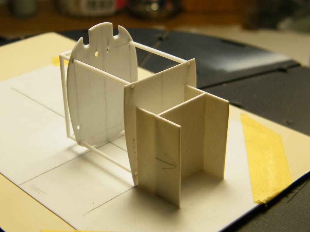
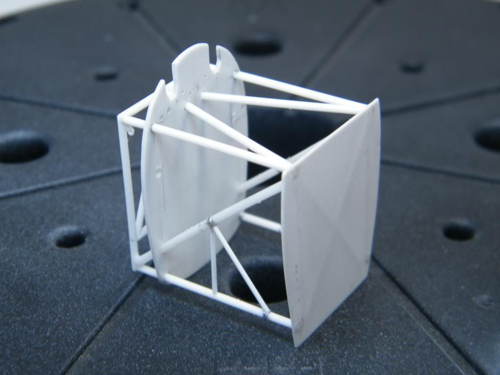
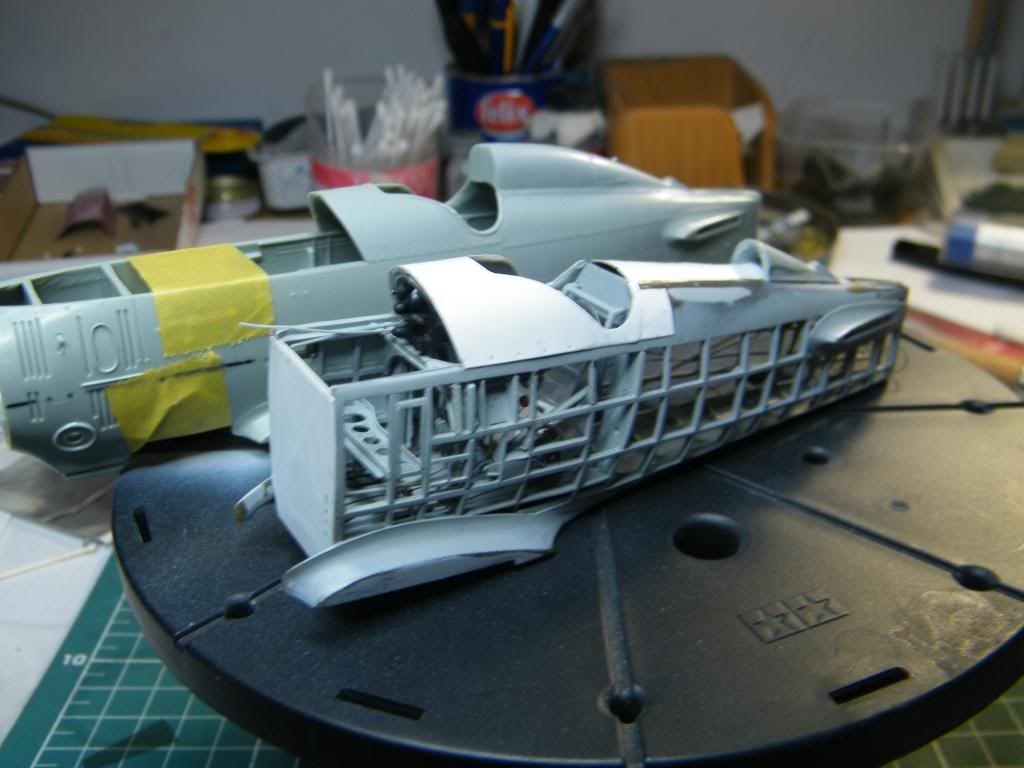
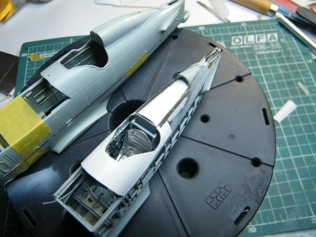
I relieved all construction of the base.
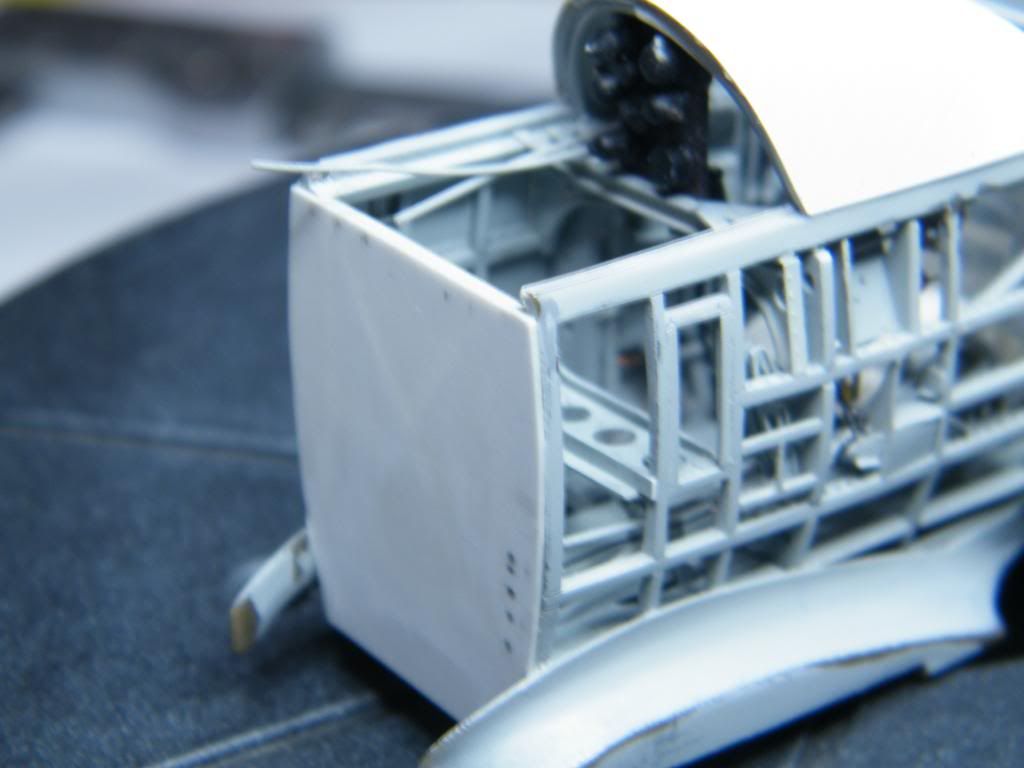
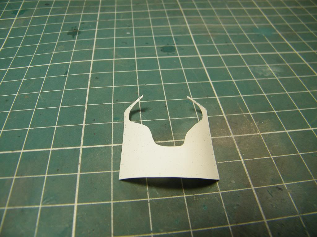
Parts of fuel tank prepared to assemblage.
First I made box from 1 mm plastic sheet.
Next I glued skin of the walls. I made rivets, cavities etc.
Fuel tank on place.
Regards
Tomasz