Leaderboard


Popular Content
Showing content with the highest reputation since 04/17/2024 in all areas
-
Thank you all for your messages. Today I took care of the two "60s". If you look at the photos, you can see a thin border around the 6 and the 0 : I decided, in agreement with myself, that this border was red like the star's border. With this in mind, I placed the masks and painted them white, placed the internal masks and painted them red: Unfortunately, the "60" on the right-hand side was completely wrong: the "60" was leaning backwards and the "60" was squinting between the white and red parts: I had no choice but to redo it entirely (You can see it clearly in the photo above.). The right "60" completely redone:24 points
-
Sometimes they come back! in the last few days I have been busy examining the shelf of doom trying to save from oblivion the works that were briefly incomplete. in this case, after countless attempts to make a frozen puddle I gave up and was pleased (well, more or less) with the last attempt. to begin with, some photos of the plane complete with the last missing details: doors, controls for folding the wings, air intakes. I added a little mud from below, without exaggerating. the engine has the possibility of being partially - or completely - exposed, thanks to the magnets embedded in the thickness of the cowling. and to conclude the whole story, some photos of the completed diorama, puddle or no puddle. the officer won a scarf out of order and all the other insignia, ranks and various insignia by Alliance Model Works decals, splendid. and I fixed one... some other updates coming soon! Cheers everyone and thanks for participating, Paolo22 points
-
Hello LSP community! It's been a while since I've spent meaningful time at my modeling bench but I'm getting that urge again. Not sure what project I want to continue on at the moment but as I'm contemplating, I thought I'd crack open the Spitfire build again and try to re-orient myself. I left off exploring the 3D-printed cockpit upgrades from Laminar Flow Designs. I'm trying to mix the Tamiya XVIe cockpit parts with the LFD XIVe-specific upgrades and adding Barracuda resin on top of that, where applicable. As usual, I am not going to claim great accuracy with what I'm doing but will use the resources that I have available to make a reasonable facsimile of an XIVe cockpit. One of these resources has been previous Spitfire builds, most notably NGBZ's VIII build from 2020. From what I know, the XIVe cockpit is based on the VIII and Gary's build does a great job of capturing some of those differences with some help of Vincent K's past scratchbuilding work. Of course, there are differences between the XIVe and VIII so I have to pay attention to that too. I started modifying the Tamiya kit parts to accommodate the LFD upgrades. The biggest change is the big electrical box that needs to be added to the port sidewall. Some surgery is needed on the kit part to make room for the electrical box. After making most of the necessary modifications like moving the voltage regulator, making a jackplate for the gun camera film footage indicator out of sheet styrene and filling in ejector pin marks, I've tacked the rest of the port sidewall components into place just to get a feel for the wiring that I'll be adding later. There is a big fuel tank directly behind the seat, which will block the view off from the seat bulkhead to the rear. This will limit visibility into the rear bottom area of the cockpit so I'm not going to bother with trying to replicate the flying control linkage wires that run under the pilot, which I was previously considering. I've done similar modifications to the starboard side, which features a resin sidewall replacement from Barracuda. My plan is to separate the cockpit into subassemblies... the port and starboard sides as presented above, the instrument panel/cockpit floor and the seat/rear bulkhead. Once these subassemblies are assembled and painted separately, I'll put them together as the fuselage halves come together.20 points
-

1/32 Tamiya F-16C #00225
chaos07 and 18 others reacted to David Mooney for a topic
Hello all, this is something i've been working for a while....the Tamiya F-16 There isn't much to say about this kit that most haven't already said as its quite an old-ish kit now and been covered a lot, but I'll add to its plaudits. Nice detail and fitting isn't an issue anywhere on the kit. I added some extra detail into the undercarriage bays using various thicknesses of solder wire, Red Fox Studio's cockpit set, mine own mask sets (DM Scale Models) for the insignia and tail codes plus my 'inspection hatches, stencil masks and canopy' set. Paints used were all by Gunze, C305 and C306 were the basic colours and various parts were base colours plus white for variation. I hope you like it :-)19 points -
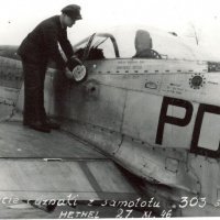
Thanks Richard, "simple and easy" camouflage, but in the end, it's more complicated and difficult to paint than I thought! I'll go on with the small details, which are very time-consuming. The propeller has a white cross on one of its 3 blades to harmonize the cockpit gun sight and the weapons. This cross is clearly visible on the photos of the finished aircraft. So, with the Cameo switched on, the mask is placed on the propeller blade, and here's the result: Exhaust pipes: of course, I masked as much as possible to protect the camouflage, then painted with exhaust metal, then bronze and finally tan. And to finish the day, I placed and glued the 2 fuel level indicators on each wing, from Eduard :19 points
-
More detail painting. The intake nose ring is now shiny inside and out. Lots of undercarriage painting going on - the undercarriage bays look very brown and un-Lightning like at the moment. This is because this aircraft (XS904, as well as XR728) have their undercarriage bays coated in a heavy layer of waxoyl (PX-32). Derek19 points
-

1/16 scale scratch built AT-38B Talon-The Smurf jet is back!
themongoose and 18 others reacted to Pete Fleischmann for a topic
19 points -
1/16 scale scratch built AT-38B Talon-The Smurf jet is back!
themongoose and 18 others reacted to Pete Fleischmann for a topic
How effin cool is this- she’s a big girl, and needs some big legs. Timmy! Engineered all of this; incorporating brass inserts vertically and horizontally and high strength resin to ensure maximum strength…and the whole thing clicks together without glue. Ridiculous. This has easily saved me months of traditional scratch building, failures, and frustration. The whole assembly just drops into the wing- Those are Timmy’s! Fingers BTW- super cool. P19 points -
Thanks Håkan for your message! Today was mostly touching up and a bit of chipping under the plane. As I had put tape on the front and back of the fuselage, it had made very sharp edges between the light blue and the 2 grays on the fuselage. So I redid these delimitations with these 2 grays using the airbrush buse/needle 0.2mm, but without the mask. Before : After : One detail can be seen in the photos at the rear of the fuselage: a maintenance hole that is lighter than the light blue tint : Under the wings and radiator I did a little chipping with blue MRP tint and white (50/50) and colored pencil. I represented dirt with exhaust soot. And I gloss varnished the underside of the wings, fuselage and horizontal stab.18 points
-
Getting back onto the subject at hand - the Malcolm Hood drive and emergency release mechanisms, I have finally got Rhino 3D representations of the parts (13 in all) that I will 3D print. It was a bit of an integration nightmare, as alot of stuff gets crammed in between the flanges of the upper longerons. And my longeron flanges are thicker than the real thing by a good bit (scaled of course). Also my longerons are not quite as wide as the real thing, to account for my skin gages, which are also thicker than the real thing (scaled). This all works against me shrinking the space to work with. Neverthless here are some hard won details that I hope will look representative once painted and assembled (assuming they print up OK): Yup - you are looking at a 3D printed chain (with sprockets). I measure, from the pictures I have, a 1/2 inch pitch and about 1/2 inch wide. Scale to 1/18, and the links are much smaller than I could scratch build (something I managed to do on the Corsair tail wheel door mechanism a while back - but the chain was a bit larger). It is alot to ask of my printer - we shall see. You also see other details that have had a whole lot of artistic license applied to them. Shortly I hope to show you the actual parts installed into the fuselage side panels. Stay tuned!17 points
-
Azur Bloch MB 152C.1 - Zdzislaw Henneberg, France 1940
Martinnfb and 16 others reacted to R Palimaka for a topic
Well, it's starting to look like an airplane...or avion. I assembled the fuselage using long tabs to make sure the mating edges will be solid. The cockpit tub was secured into the fuselage from underneath after a fight. It required some sanding and thinning of the walls to fit. And typical of some Azur kits the fuselage requires a bit of juggling in a few spots to make it all work. I placed the windscreen on the fuselage while dry-fitting and it was a bit wider than the opening and fairing it was meant to fit. I was afraid that if I forced the sides of the windscreen in later to fit it might break...it is beautifully thin and clear. In the end I left a gap on the top so that the windscreen would sit properly, while not making the gap too wide which would cause problems at the bottom where it matched up with the leading edge of the wing root and the rear of the engine "egg". In the end I think it will work and I'm happy. I added the horizontal stabilizers ( out of sequence of course ) and they required sanding and filing to thin them to match the fairing on the fuselage. In hindsight it would have been easier to sand them thinner before gluing the halves together, but... Anyway, they fit now. The tailplanes on the aircraft had a 2 degree dihedral and I had to be careful to set that properly. The structure on the back of the head armour, and the filler cap in place. I've cut the slots for the hinges into the leading edge of the elevators. Next step is to cut the hinges out of plastic card and secure them in the trough at the back of the stabilizers. Richard17 points -
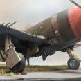
Didn't like the numbers on the side (zero was too narrow) so I stripped them and replaced them with new numbers. Got some guns on board made from .060" aluminum tubing. The ID was much too small so I chucked them in my spinning device and opened them up and then stuck the opened ends in a buffing wheel to homogenize (smooth) the ends. It's actually browner in person, so how'm I doin' ? Critique welcome.17 points
-

Another Kotare Spitfire - Mk.I (Early)
TankBuster and 15 others reacted to Shoggz for a topic
Two hours tonight spent on the instrument panel! ..and I think it was worth it. Doing an IP this way pushes the old decaling skills. For me, the art is to try and hit that sweet spot where you have enough water on the decal to allow you to manoeuvre it, but not too much so you flood and disturb what you've already done.. Got the seat constructed and painted too.16 points -

1/32 Trumpeter P-51B Mustang with Aerocraft corrections
LSP_K2 and 15 others reacted to Tolga ULGUR for a topic
Some progress Matt coat applied after oil paint washing16 points -
Suggestion of 1:32 Sunderland and Halifax from HK Models
scvrobeson and 14 others reacted to tomprobert for a topic
Yup… a 1/32 Sunderland is huge!15 points -

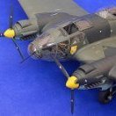
Revell/ AIMS 1/32 Junkers Ju-188 E-1 Z6+DM II/KG66
Fanes and 14 others reacted to monthebiff for a topic
With the engines painted it was time to move on to one of the really tricky parts of this conversion which is getting the nacelles mounted to the wing as there are no positive attachment points at all. I've been pondering this issue for such a long time now (Erm, just the 7 years) and after painting up the engines at the weekend realised it's a pretty simple and clean solution to the problem! With the engine secure inside the nacelle I then carefully taped it into the correct position on the wing and ran a drill down through the centre of the engine into the rear engine bulkhead And with a suitable piece of aluminium tubing inserted I was then able to slide the nacelle in to place and all nicely aligned I then cut the tube to the correct length as this will also then act as a nice positive location for the propeller Pretty happy how that's worked out so far, next up I will build up the prop hub and fan so I can get good alignment of the cowl ring before gluing in to place. Regards. Andy15 points -

Going to the deep side : U-552 DKM 1/48
Archimedes and 13 others reacted to red Dog for a topic
And resupply U-boats, providing fuel, munitions and food supply to the other attack boats. The story is quite interesting. I stalled a bit on the forward torpedo room because of the empty foreground. Trumpeter wants you to simply place two air tanks there but that leaves a lot of empty spaces and play against the cramped area I want to try to depict with this build. These tanks are not correctly located and are partly under the bunks. But if I build bunks on top of them they will be too high so I decided to cut the floor, create a 3D piece to mirror the opposite side and display the lower bunks. The tanks are relocated and attached from above. If I add a floor for them I'll hide too much of the torpedo storage room under the floor of the room. That's not perfect but the best compromise I could come up with. I intend to show a lot of supplies throughout the boat and try to render the mess it must have been in there with 40-50 stinking males confined in there. I went to cult-3D and downloaded as much stuff as possible and scaled them to 48th scale. Plates, coffeepots, cooking pots, rice bags, potatoes bags, tin cans, fruit cases, salads, carrots, 88mm shells & cardboard casings, etc . All these will compliment nicely what I could gather from black dog supplies. I just haven't found ham and sausages yet but I want them to hang from the floor and I am thinking about hanging hammocks full of supplies from the roof of the torpedo room. Here's very early impression of what I am leaning to: I am also debating to put 2 more torpedoes on the floor as it was often done, must made the crew life really difficult14 points -
1/32 Trumpeter P-47D-22 "Kansas Tornado"
chaos07 and 13 others reacted to Tolga ULGUR for a topic
Some progress Oil paint washing applied. And landing legs installed14 points -

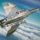
RAF FG.1 XV571 WILD HARE Phantom Conversion
Fanes and 13 others reacted to Anthony in NZ for a topic
Thanks Kev, loving your airliner builds atm by the way! Thank you Niels! Really appreciate it LOL I dont think I will know what to do with myself once it is finished. Actually I am kinda hoping the Icelandic Fine Arts FA.2 Seaharrier or my good friend Tony's 1/32 Wasp he's printing me... Although I should finish some stuff too lol Hey Matt, yeah the new leg looks awesome dosent it? I've done a few structural 'tests'and it is pretty darn strong, I have no worries it wont hold the weight of the kit Thanks buddy! means a lot coming from you Thank you sir! It's not without your help and photo's we could get it so accurate! Thanks John, I am super pleased you are still hanging in here! I am still using your Phantom for some of my refs Thank you! Yes that noseleg is is very different when you know. Thanks Chris! Really appreciate it my friend Small update tonight Undercoat of silver done before a little more tidy up on stuff you just wont probably see On with some colour, sheesh that red is bright! Now toned down with an oil wash and flat coat. This area got quite oily and sooty, considering how filthy the belly of the Phantom got it probably should be worse, but I didnt go too overboard On to something else now, running out of things to do before paint! Cheers team, appreciate your feedback and likes Anthony14 points -

HPH / Infinity Blohm-Voss BV-138 in works
Rick Griewski and 12 others reacted to Jan_G for a topic
Mirek posted pics of finished model on modelforum.cz it should be available to order during the May https://www.modelforum.cz/viewtopic.php?f=6&t=15282413 points -
It was quite a ride, but I have a Malcolm Hood mechanism to show you. This is what I am trying to represent: The chains, the emergency release pushrods, the sprocket support fittings, the crank handle, the emergency release handle, and the black cover plates. Not the cross-tube. That comes later. First, just as what happened so many times back in the 1940's when -B's and -C's were getting their hoods, I had to relocate the recognition light switch box on the windshield frame. From here: To here: Had to be done to clear the new crank handle. All the parts printed up pretty well. There is alot of small detail, especially the chain itself, so I went with the 30 micron thickness setting on the printer (I normally use 50 micron). After careful removal of supports, and carefully painting, I got this collection of details: And I had to be exceedingly careful at all stages of preparation - the long thin parts are so very fragile. The black plates are not 3D printed - just old fashion scratch build with styrene sheet and Meng nuts. Ok that was the easy part. Installing these details into the airplane was the hard part - a most stressful and "stimulating" experience, trying to pry into a small space all these parts without breaking anything. I broke one of the chains, but had a spare and used it. Everything else worked out OK, sort of. Pictures: The 3D printed chains are a success, I am happy to announce. Let's see the finished mechanism in the fuselage jig: I need to do a better job painting up the rollers - I know. But that comes later. Glad to put this sub-project in the rear view mirror! Next I believe is a bit of miscellaneous clean-up chores, and then the lower radio floor and the fuselage tank. I've been waiting forever to get started on that. Hope you like the chain drive! Later.12 points
-
1/32 Trumpeter P-47D-22 "Kansas Tornado"
chaos07 and 11 others reacted to Tolga ULGUR for a topic
A small update12 points -
1/32 Trumpeter P-51B Mustang with Aerocraft corrections
chaos07 and 11 others reacted to Tolga ULGUR for a topic
Some progress The propeller and spinner of the kit - like many other parts - do not look good. I found the Quickboost set produced for Tamiya as most suitable spinner. Still not suitable 100 percent, but I'm bored enough so I'll continue as it is.12 points -
A little progress over the last week - a mix of Airfix kit, Airscale and Quinta. Photos have flagged up a few things I need to improve - but bear in mind most of these images will be showing at larger than life-size. And with the seat section dry-fitted. Now working on the seat - and the next two formers (partially drilled out). Blue skies... Iain12 points
-

F-117A Nighthawk, 1/32, parked mode
chaos07 and 11 others reacted to F`s are my favs for a topic
The storage case and the bombs are aready, so I'm starting the ''parked'' sessions... firstly - just a few nighttime pics with a flashlight: (btw here is the WIP topic, and the in-flight pics) I'll take some ''normal'' outdoor pics soon.12 points -
Revell/ AIMS 1/32 Junkers Ju-188 E-1 Z6+DM II/KG66
John1 and 11 others reacted to monthebiff for a topic
Some more done and needed to fit the cowl rings to the engine nacelles but to do that I needed a basic prop/ backplate/ fan assembly so I could glue the cowl ring in place and be able to remove and re-fit without fouling the cowl ring. And both completed and fitted in place Time next to look at the aileron extensions as definitely some serious work seeded The R/H has already been started on but as you can see from the L/H part much careful sanding and reshaping is needed. Regards. Andy12 points -

(RFI) S.M. 79-II „Sparviero” 1:48 Trumpeter
scvrobeson and 11 others reacted to Kriss for a topic
And another model completed and the photos go to the gallery, S.M. 79-II "Sparviero", 283 squadriglia, 130 gruppo autonoma, Mediterranean 1942. feel free to visit the gallery.12 points -

Recce Voodoo
F`s are my favs and 11 others reacted to Dandiego for a topic
Slow progress this week. Working on getting the intakes glued together and sanding out the step on the inside. Finicky to say the least. But I think I am there. I also removed part of the round part of the duct. You can't see this part of the duct when installed and it makes painting much easier. Dan12 points -

USS Constitution Tribute Build
Hartmann352 and 11 others reacted to Greif8 for a topic
Though I have not posted any updates recently, I have been either researching or testing techniques on mockups. After a lot of reading about how running rigging actually worked, and then testing some ideas over several bench sessions, I finally arrived at the stage where I feel like I can put the sails on the yards and then either rig to show them brailed or clewed up, or deployed to catch the wind. Following is the Mizzen Royal sail, that I have rigged clewed up. Detail shot of part of the sail "bent" to the yard. Due to the scale it is not possible to bend sails to the yards as they would have actually been, so I used a technique I learned from a very good sailing ship modeler. Though I did not get everything perfect it actually looks pretty good when the entire process is complete - IMHO that is! This poor shot shows the two different lines that were either attached to the lower corners of smaller sails, such a Royals; or blocks positioned at the lower corners of larger sails. The smaller line on this sail will be run through the clew block and the larger line will be run through a pair of blocks on the Topgallant yard below the Royal sail. The lines in place. On actual ships they work in together as we shall see. Ok stupid me, ignore the image above, below is the correct one. The small frays will not be seen once I have clewed the sail up. For sails that will be displayed as deployed I will have to make sure I get them cleaned up. An example of how this part of the running rigging works. I have pulled on the clew line (the smaller one) to bring the corner of the sail towards the center of the yard. The heavier lower would have been slackened on real ships to allow the sail to be clewed up. The process was reversed when the sail was deployed. Though I still need to make some adjustments to the footropes, and do some minor forming of the sail, it has now been "clewed up" just as it would have been on sailing ships of the day. I brushed on watered down white glue so that I could shape the sail and also stiffen it in place when dry. I then bunched it as would have been done on an actual ship and tied off what were known as long reef lines to finalize the placement. I made sure to keep the two rigging lines clear as they will be run down to their respective location on belay pins and tied off later on. Photo of the front. Again, I did not do a perfect job here, but I think it looks the part. I still need to do some minor cleaning up and shaping, but this Royal sail is almost done. I plan to do the Main and Fore Royals next. The huge challenge is going to be "brailing up" the Main and Fore Courses as there are a lot more moving parts and the yards are much more crowded than the Royal yards. Keeping my fingers crossed I am up to the challenge. Ernest12 points -

AIMS new Bf 110 G-4 and Ju 88 G-6 decals
LSP_K2 and 10 others reacted to Pastor John for a topic
Hi everyone, in the post a few days ago from Ukraine, the decals for my AIMS 20th Anniversary since my first ever Ju 88 G-6 product - decal sheet 72D002! This is a large set - 2x A5 decal sheets for 27 options! The decal sheet is designed for those who have bought the 1/32 AIMS conversion set and so some of the markings that are needed - like the crosses - are on the the decal sheet that comes with the conversion set. The printing consists of 13x sides of colour instructions on 135 g/m2 glossy paper - unfolded - in a nice A4 clear envelope. Set with printing = £30.00 (plus shipping) Set with downloaded instructions = £22.00 (plus shipping) This set is only available direct from me Email me at aimsmodels1@gmail.com if interested. Also in the post.... AIMS 32D037 'Bf 110 G-4' With the decals printed for the conversion set all gone a new sheet has been printed as a 'stand alone' product. The conversion set will henceforth be still available but without decals. This way folk can buy the stand alone sheet if they already have the original conversion set. Product is £20.00 available direct from my or Hannants when they order Thanks for looking Best wishes, John11 points -
1/32 Trumpeter P-51B Mustang with Aerocraft corrections
Brett M and 10 others reacted to Tolga ULGUR for a topic
A small update I worked on the landing light I used resicast lens as the light. Instead of the clear plastic cover part, I used clear cello tape.11 points -
But wait, there's more! Out of curiosity, I decided to break out one of my Minicraft 777 kits and compare their respective fuselages. To my surprise, they match pretty well! I've made a small start with the assembly on this one, starting with the fuselage. I cut out and shaped the internal bulkheads, as well as filling the provided wing spar with Milliput: These bulkheads never fit well, so you just have to make the most of it. Having learned some valuable lessons from the (still unfinished) 757 build, I decided to number the bulkheads front to rear, and mark their respective positions on the inside of the fuselage: As you can see in the photo, I also added some styrene stock to aid with positioning and gluing. And glued in place: Note that I've also cut out the opening for the nose wheel bay. Since I bought the Bra.Z resin replacement nose for the Minicraft kit, which includes a moulded-in wheel bay, I decided to rob that kit's one-piece nose wheel bay for use here: And a test fit: The fuselage join will definitely need some internal tabs to help with strength and alignment, and have a better idea of how to go about that from the 757 build. I'm not sure if I'll use that dinky spar for the wings or not. It's easy enough to slide in or out as required, so I can make that decision later. I also mustn't forget to add some nose weight! This build won't be a priority for a while, but still has a bit of low-hanging fruit I can harvest before it requires my full attention, so look out for another update soon! Kev11 points
-
Here the white demarcation band and rudder have finally been painted, using Gunze gloss white lacquer. As is all too typical for me when shooting gloss, I got a wee bit heavy handed and will now need to sand those ridges off. Next up, the fuselage light blue. I’m so excited!11 points
-

Spitfire Mk.1b - Kotare 1/32
scvrobeson and 10 others reacted to Azgaron for a topic
Thank you Kev and Andy! The fit sure was tight. If I ever build one more, I'll try glueing the fillets first. I did a pre-shade with brown and then painted the underside with sky type s. Then I masked the underside and gave the topside a black pre-shade. Then on with some dark earth. Some black goo was applied to mask the camo. Dark green was painted and then the goo was removed. I wasn't happy with how some of the camo turned out, so I applied goo again. Don't leave it on too long though! After a few paint sessions it looked like this. I accidently got some overspray on the underside. Easily sorted! I've clear coted the plane and have started with the decals, but no pics yet, so this is where I'm at right now. Håkan11 points -
Suggestion of 1:32 Sunderland and Halifax from HK Models
chrish and 10 others reacted to tomprobert for a topic
Well considering HK are rumoured to be following my lead with their 1/32 range (by lead I mean I spend 2+ years building a vac and then an injection one comes along!) you can count on a Stirling being next11 points -
1/32 Trumpeter P-51B Mustang with Aerocraft corrections
chaos07 and 10 others reacted to Tolga ULGUR for a topic
Decalling I used Kits Worlds decals. National insignias are from an old CAM decals set.11 points -
Ok, here we go.... This is my latest attempt at the F-16 by Tamiya. I tried the Thunderbirds kit a long, long time ago but got stressed out and binned it (this was long before it went OOP). Fast forward to now...I saw the latest Have Glass V scheme on the Block 50 aircraft and decided to: Create a model based on the HG V scheme Create decals for at least one aircraft (I ended up creating markings for three so I have a choice). TBD - I've still got some outstanding decals to create, mostly stencils for the pylons and things like that. Aside from the F-16 kit, I've assembled a good selection of aftermarket to include: Quinta Studios F-16 cockpit set Phase Hangar Resin JHMCS sensor (for the canopy rail) Reskit AIM-120Cs Reskit AIM-9X Reskit GBU-54 bombs Reskit BRU-57 SMART bomb rack Reskit F110-GE Exhaust Nozzle (Open) Wolfpack Aces II Seats (Late) Eduard GBU-39 Small Diameter Bombs w/BRU-51 rack I'm still on the hunt for Master AOA probes and possibly, a set of static dischargers although I can probably create these myself with the stainless rod and tube I have in-house...we'll see. I'd love to get a set of stabilators from Kopecky Scale Models but I'm too late there...all sold out. So, where to start? I decided on the AN/ALQ-131(V) deep pod... No particular reason other than it's as good a place as any. The Reskit 131 pod looks absolutely fantastic in the box and when coupled with the Kopecky Scale Models AN/ALQ-131 pylon, it'll be dynamite! There are three main parts, the two ends and the body...simple. The fit is pretty good. The mounting lugs, electrical connection (at least that's what I think it is) and the 4 stabilizer points (again, not knowing what they're actually called) fit into the drilled holes on the top. Each part has positive locating pins and in order to make sure it fits correctly, you need to have the pylon you're going to use handy or you may be sorry later on. The electrical connection (immediately in front of the forward mount lug) sits in a recessed box; again, with a positive locator on the parts. I'm trying to make my photographs informative (like the ones Chuck does in his builds) so I've added commentary to the photos. Next up will be primer and a coat of 36375, gloss coat then decals. Yes, the Reskit pod (and indeed a lot of their other items) come with decals.10 points
-

Phantom lovers, beware!
Jim Mason and 9 others reacted to Eli Raphael for a topic
Zotz decals is now preparing five sets of 5 profiles ea. for the Red Pill F-4B/N new kit. Also, another set for the RF-4C in the Vietnam war. We are finishing a set of B-26 B/C Marauders for the 1/48 ICM kit. (Wanted a 1/32 kit, maybe coming later?) Good times (hopefully) coming soon. Thanks10 points -
Greetings, A minor update, but a bit of work to get here for this week. On the export Block 50/52+ aircraft, the traditional wedge-shaped cooling vent is replaced with an open-style vent with six prominent openings and visible trunking or fins internally. The Grand Models CFT set had some PE to create this vent, but only the outer opening. Fortunately, this panel is proud of the surface like a doubler, so adapting the PE was much easier than recessing the part. After cleaning up the PE by filing the edges with a diamond file and slightly rounding the edges over with 400 grit wet or dry sandpaper, some profiling was needed. I used my Hasegawa scribing tool, which has a larger diameter handle, that is consistent across the length. I rolled this tool across the panel along the axis of flight to give it a slight bow to conform to the fuselage. After attempting to profile the part by rolling the tool across the part on my cutting mat did not work, a small tray that had some silicone poured into it was used, and that provided the right amount of flex to do the job. With some firm pressure, a half-dozen passes across the part formed it into the correct shape. Then the PE part was located per references found on the net, and the Modern VIper Guide which has been so helpful so far. After being taped into place, a Sharpie was used to color in the openings to leave behind the area that needed to be removed. With these marks in place, an opening of approximately 3.4mm x 8mm was decided on, which will allow for the small box to be built inside to house the fins or vanes for this vent. This opening, if kept square would make my next job much easier, so layout was critical in my mind. The Infini cutting mat B has a grid laid out in 1mm squares. Some Tamiya tape was laid out, and a 3mm x 8mm area was removed so I could lay this on the fuselage and allow for proper positioning ensuring the correct area would be removed. Putting it back after would be problematic, and would complicate the attachment of the PE as well. I was able to index the forward edge of this opening to the panel line just ahead of it on the avionics bay with a 3mm parallel front edge. This ensured that it remained square to the waterline of the aircraft. A second tape layout template was made and then applied to a length of Dymo tape, which was then cut out to the same dimensions. Aligning the openings made this alignment much easier. In my experience, Dymo tape either sticks like its life depends on it, or it does not stick at all. Especially across curves. My thoughts were that the underlying tape would allow for easier removal, and the Dymo tape would serve as a better scribing guide rather than taping down a flexible guide which would be moved several times. A thing Tamiya scribing tool, .015mm was then used to scribe the outline fairly deep, then the tape was removed (with considerable effort - this time it really stuck in place), and the panel was finished freehand. Minimal clean-up was needed with a file, and we had a square opening for the internal portion of the vent. VMS thin black CA worked like a champ to attach the PE. A tape hinge ensured that it was in perfect alignment with the opening and made the initial glue-up a breeze. A small amount was applied with a micro brush to the middle of the perimeter of the part and then pushed into place. After holding it for a couple of minutes, more was wicked around the inner perimeter (inside) and outer perimeter with a CA applicator (the glue looper if memory serves). After a bit, some VMS Debonder and some pointed cotton buds made short work of cleanup. Note the black CA filling in a sink mark below the aft portion of the canopy - and the errant line on the hinged panel has been repaired with clear CA, but still shows the brown panel liner. Inside a basic box was built up. The underside was sanded flat, and marginally square to the opening sides. A couple of thin runners of .030 evergreen were laid down across the length of the vent, and then two sections of .010 were glued in place to make the sides of the internal structure. Below I also have the .005 evergreen strips which will define the internal structure dry fit to verify they will look the part. Later this week they will be glued in one by one with CA from behind (aft side) to hide the glue lines. Once glued in, the added length will be cut back flush with the "box" sides. All this fits nicely inside without interfering with the cockpit tub or the lower fuselage. And the view with the same temp slats in place. Looks the part to my eye! With the macro photos, it does appear that one side of the opening is more round than the other, as installed it is to the rear. In-person, this is not so obvious. Had this been more prominent before it was glued down, I would have reversed it making the aft edge the "square" side, where the internal structure meets the outer openings. This should be the last of the fiddly bits to do before the fuselage is ready to come together permanently. Thanks for checking in!10 points
-
Dart logos added to the nose - and Air League 'sticker' on the rudder... And a reprint of the engine - wasn't happy with the last - in process of getting some paint on the new one. Oh, and the 'blank' for the instrument panel. Have fun... Iain10 points
-
A little bit of progress! The propeller, spinner and bombs got a clear cote. So, now they're ready for decals. I started painting different metal shades. I think I'll keep it there and start painting the nose next. Håkan10 points
-
1/48 Special Hobby Airspeed Oxford
Archimedes and 9 others reacted to Derek B for a topic
In between working towards finishing my Trumpeter 1/32 EE Lightning F.6 model, I have started on this 1/48 Special Hobby Airspeed Oxford kit. It will be a companion to a 1/48 Rolls Royce Armoured Car (both are being made for a friend) that I have completed, but not yet painted. This aircraft will represent an aircraft used at RAF Habbaniya in 1941 and was used as a bomber in a local conflict, so the first job is to cut out the bomb bay doors (I will have to scratch build the bomb bay and bombs/bomb carriers) - other than that (and markings), the rest of this kit will be built OOB. Derek10 points -
Thanks Paul, the cockpit certainly is busy but I'm taking the "less is more" approach on the Typhoon, I really can't see the point in agonising over detail that isn't going to be seen, especially since the canopy may well be closed. I'd like to find a seated pilot figure but they aren't often modelled. Yep, see above Dennis....and below for that matter re- the gunsight! You've got the tee-shirt! Bound to be a) easier and b) more detailed but as a "Silver Wings kits" builder, and all that those kits entail, I'm loving this Tiffie. I'm currently doing the IP, the decals supplied with the kit are perfectly good as far as they go but there's no dial showing the status of the landing gear, and the compass face is far too small so I'll be dipping into my Airscale supplies shortly. I had researched and labelled the function of each dial: And as is right now: Looking ahead to the next stages, the placement of the gunsight needed a bit of research but this picture tells it all: Fitted onto the front of a curved bar. There was also a later type evolved by Roland Beamont that fits behind the bar: Don't know at the moment when this was introduced but the earlier type will do for me. This with a very necessary "crash pad", home made?: And looking even further ahead, the wing to fuselage join looks promising, in fact I've seen IM models with worse fits:10 points
-

Hasegawa FW-190D "Late Version"
Shoggz and 9 others reacted to Rampenfest for a topic
Quick little update (again) Managed to find a tad more time to tighten up the demarcations. Also, I had to remask and spray the Braunviollet along the wing roots again, which is tedious to say the least. Lastly, I decided to make the fuselage green colors a bit more bright, as that is what the Eagle Cals profile suggests…..also, I like how it looks. I mixed some Vallejo RLM25 light green with RLM 83 dark green to get a middle ground green. This will also be used for the mottling as well on the fuselage and tail. Cheers!10 points -
Progress continues on the sails. I have shaped the sails that will be deployed, and prepared the sails that will be clewed or brailed up. I bent both the main Royal Sail and the main Topgallant Sail to their yards during the last bench session. The following photos show some of the progess of that. The main Topgallant Sail after shaping, and awaiting some final prep work before the process of bending it to its yard begins. I used the kit sails as forms to shape the sails that will be deployed. I did this by watering down white glue 50/50and brushing it on the sails while they were laid atop the kit sails. This worked pretty well, and I can also do further shaping as required because while the sails have been stiffened they are still flexible. The stiffening process also helps greatly reduce any fraying. The lower corners of actual sails during the age of sail had rope looped through them. This was reinforced by banding or wrapping additional rope and sewing it into the fabric of the sail. I final band was added just past the tip to give the loop final form and strengthen it as well. I replicated as much of this as possible in scale to try and get a more realistic look. The first shot shows the front of a corner and the second the rear. The main Royal Sail bent on it's yard and clewed up. The main Topgallant Sail bent on its yard. I was very happy with how this turned out though the process is very concentration intensive as you have to make sure you run the bending line correctly, don't cross other lines, and keep any blocks free. I had to re-run a couple of wraps to correct one of those issues. I'll be honest that I am suddering at the thought of bending the main and fore Courses to their yards given how "busy" those two yards are. A close up of the Topgallant sail on the yard. The only wrap that I did not nail was the center one. Due to the amount of "stuff" where the yard and mast meet, I could not thread the line like I wanted. I am going to try a different tack on the next sail in this area. Rear view of the main Topgallant Sail. You can see just how many lines there are, and this is not all of them! I ran the clew line and the sheet lines. The clew lines are the slightly smaller ones that I have used to clew up the Royal Sail. The thicker lines running through the blocks are the sheet lines. I will place all these out of the way when I step the mast and run the lower shrouds and stays. Finally a close up of the rear of the clewed up Royal Sail. You can see one of the clew blocks doing the job it's name implies. I am trying to make both the standing and running rigging as accurate and functional as possible, taking scale limitations into account. When I clew up the Royals for all three masts I am actually running the lines and pulling them to shape and position the sails as they would have looked when clewed up. Clewing up the Royals is actually pretty easy as there is not a lot of lines for those sails and figuring out how to "work" them was really not that hard. On the other hand, "Brailing Up" the main and fore Courses is going to be a much more complex process as there are several different lines and blocks that have to be "worked" to get the right look. I am looking at that project with a bit of trepidation to be honest. Well, the "top hamper" is starting to take shape. Hopefully in a few weeks the sails will be mounted, the masts stepped and secured, and the standing rigging complete, but it is a slow process. Ernest10 points
-
Pix or it ain't true ...10 points
-
(RFI) Northrop P-61A „Bleck Widow” w 1:48 z GWH
D.B. Andrus and 9 others reacted to Kriss for a topic
Finally managed to take photos for the gallery, I know photos taken quickly but you can see something on them. I invite you to view the gallery of the Northrop P-61 A "Black Widow" model. - "Lady Gen", Florennes, Belgium, december 1944.10 points -
P-47D Thunderbolt - Hasegawa 1/32
R Palimaka and 9 others reacted to Azgaron for a topic
The problem areas was sanded and where needed sorted with sprue glue and sanded again. Then I gave it a new cote of aluminium. Freshly painted, but I think I need to give it one more cote where needed. The pilot was finished and the mask glued in place. I'm quite happy with how he turned out! Håkan10 points -
Back with an update. Progress has been slow but steady. After hosing the interior down with a broad brush, I spent some time getting the Eduard cockpit and HGW seatbelts around. I added just a little weight to the cockpit section with lead sheet. This is something like a pound of weight. The interior... given the size, this thing is difficult to photograph. Ammo boxes-o-plenty. A rough fitting of the fuse halves. The fit wasn't great. There's enough openings in the fuse to verify that all internal bulkheads were located correctly, but still there was a decent gap between the halves in the upper spine above the ball turret and another on the bottom between the bomb bay and nose wheel well. Break out the super glue. The canopy actually fits nicely. The aforementioned upper gap. The also aforementioned lower gap. Glue applied! Channeling my P-38G conversion from a year ago, it's time to slather on the super glue and sand things down. Fortunately, Trumpeter's lackadaisical approach to panel lines means that there was not a ton of detail to worry about having to restore afterwards. While the glue was curing, I moved on to the wings. The gear bays are monstrous things. Starting to look like a Liberator. Here's something I'm not too thrilled about. The instructions call for sandwiching the wing halves over the heavy spar piece then... I dunno... it looks like you're supposed to screw them together, but there's just so much wrong with that idea. There are no screws included with the kit and assembling the wings in that manner would leave you no option than to try to paint this monster as a single, complete unit. That ain't happening as there's no way to maneuver it around my paint bench when fully assembled. Sooooo, these 4 studs gotta go. Easy peasy... the wings now slide on without trouble. The wings with control surfaces. I had to sand down the hinges for all the control surfaces because they were too wide and interfered with the control surfaces themselves. Annoying, but not a show stopper. Once nacelle installed before running out of steam today. The fuse halves are filled and looking good, now I just need to do a bit of rescribing. This thing is a monster. I gotta say though, aside from its overall size, it's not a very inspiring kit. Everything is big, chunky, and heavy. There's very little in the way of small details - everything is big and chunky. Ah well, there's no other show in town, so we'll make the best of what we've got.9 points
-
Revell/ AIMS 1/32 Junkers Ju-188 E-1 Z6+DM II/KG66
Fanes and 8 others reacted to monthebiff for a topic
So it's been a while but suddenly decided the 188 needed working on again. I decided to ease myself in gently and work on the engines. I'm not using the AIMS supplied resin parts but instead a couple of Revell Fw-190 engines instead as these although not 100% accurate allow a lot more surface detail when painted and propellers will be from Eduard The Eduard prop set is so good, I've used one before on my F-8 build and is super nice to work with. I've several issues to deal with on the wings but felt getting the engines completed was a good starting point. Regards. Andy9 points