Leaderboard
Popular Content
Showing content with the highest reputation on 05/13/2022 in all areas
-
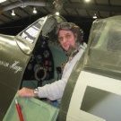
1/32 Trumpeter EE Lightning F.Mk.6 XS904
TimHepplestone and 11 others reacted to Derek B for a topic
On the home stretch...(Parachute withdrawal cord/strop). And ejection seat handles and headrest/parachute pack restraint straps. Face blind firing handle restraint strap tunnels. Harness 'Go-forward' lever. Ejection seat detailing complete. And after a coat of primer. Definitely an improvement over the supplied kit detail. Derek12 points -
decisions, decisions... set! NAA P51B Trumpeter 1/32
Model_Monkey and 8 others reacted to mc65 for a topic
thanks Ernest and Maru, you are too generous with this dumb old model maker! well, today I have not done anything because I was ordered for "a simple ride, less than 10Km". since this discussion has taken a bit of a drift like this, I put a photo of the green part of the route: I have yet to figure out if the sweet* girl who drags me into these things is trying to get me in shape or kill me... anyway. in the midst of this alien landscape, and without even thinking about it, I had an epiphany, and I understood why the P51's main landing gear was struggling to stick firmly in place. in fact, it is almost a week that I have placed it, but it limps, flickers, in short, it is not firmly locked in its place, on the contrary, to titillate it, it comes off, despite the use of very powerful styrene glue as flex-i-file! AND THANKS! the landing gear bay is made of resin, and when it sticks, the styrene glue, there??? I could stay there until 2024, waiting for it to stick... so now** I clean everything and start again with a suitable glue and then insciallah, I finally go to the cockpit. oh, yesterday I managed to complete also the LH ammo bay. cheers, Paolo *so to speak **now I'm going to rest my poor bones, we talk about it tomorrow, maybe9 points -

****Finished**** 1/32 Great Wall Hobby - P-40 Curtiss Hawk "Flying Tigers"
TankBuster and 6 others reacted to Tolga ULGUR for a topic
And here it is: I have used Barracudacast main whells which are designed for Trumpeter kit. But no chance for the tailwheel . It is from the box. And the seat. I have used Eduard seatbelts.7 points -
Sprue Bros Lightning Deals - Hasegawa Ju87G Stuka "Kanonenvogel"
scvrobeson and 5 others reacted to ivanmoe for a topic
Lightning sale has come and gone.6 points -
Many irons are in the fire right now on the F4U. Before I continue the belly skinning effort (which intimidates me), I need to get some 3D print parts in the pipeline. Only one is going to be used soon (the shoulder detail), but to make the order worthwhile I want to include some others. So the next order will be the shoulder, some cowl flap mechanism details (x 18), the tail wheel, and a locating tool for when I install the nose cowl. This has all required Rhino modeling which is what I have been doing the last few days. That plus some coordination with Airscale for some decaling he is so graciously helping me with. You all will agree Peter is pretty awesome. Descriptions follow. Recall I discovered that my subject will not have the production "dead flap" as I once thought. Instead it will have 360 degrees of cowl flaps. This required me to create a diaphragm shoulder to replace the dead flap detail: The top red part is the "dead flap" which will no longer be used, even though I have the 3D print part in my hot hands. A waste... The lower red part is the replacement shoulder detail, which I will send out to be 3D printed. I am going to need that part pretty soon. The silver shoulder parts, I already have. I will need the shoulder parts pretty soon. It will also not be very long before I (attempt to) install the nose cowl. I have it already, 3D printed a few weeks ago: Cool? Note all the internal stiffening ribs, which will be quite visible, and which are used to attach the cowl to the engine cylinders, just like the real thing. This will be a helluva adventure when the time comes. I have been working on a fixture concept to accomplish this: Probably confusing, but you will see once the process begins. That orange part is going to be 3D printed and will go out with this next order. After the nose cowl is installed, the cowl flap ring, cowl flap mechanisms, and the flaps themselves will be installed - probably an even bigger adventure than the nose cowl. There will be a fixture for that too, but I probably will not need to 3D print any parts for it. We'll see.... But I do want to 3D print some of the mechanism parts, which I have been designing in Rhino: The mechanism: I will 3D print a couple of those parts, and there will be 18 of each. That will also go out with this next order. To help fill out that 3D print order, I decided to include the tail wheel. Aft fuselage work is not that far away, and the tail landing gear will be a big deal. Here is a Rhino model of the tail wheel, which tried my patience for the better part of two days: I used this fantastic drawing to design the Rhino part: That is the land wheel/tire, as opposed to the much smaller (and solid I think) combo used on carrier decks. I think y'all will like it. That tire has a realistic flat, tilted about 3 deg, so I can have it in a swiveled orientation. It will gather dust a while when I get it, but that's OK! In addition to some 3D printing needs, I am anticipating exterior decal needs before too long. Once I get the skinning finished on the forward fuselage, create a big cowling over the engine accessories compartment (yikes!), and get the shoulder details installed, it might be good to apply the tri-color Navy top coat, and maybe decals. It took some searching, but I found the decal drawing: And I managed to design the skull & crossbones that all VF-17 aircraft sported: I am going to get some help from Airscale on some of the decals, including the skull & crossbones. But most of them can be done via my current method using my inkjet printer and decal paper and the Testors decal program. I will be working with Peter for a while in the short term to get all that sorted out. Ok, must get that 3DP order out, get some decal data to Peter, and then quit stalling and tackle that skinning! Anticipate slowing down some, as spring as sprung and many activities compete for our time. Keep watching this space - pretty exciting things cometh.6 points
-
****Finished**** 1/32 Great Wall Hobby - P-40 Curtiss Hawk "Flying Tigers"
Uncarina and 5 others reacted to Tolga ULGUR for a topic
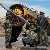
Some progress.6 points -

Aussie Mirage III D ( scaleworx conversion)
Anthony in NZ and 4 others reacted to alain11 for a topic
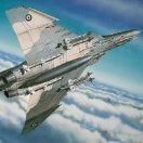
Hi gents do you like the Mirage ???? I do !!!!! . So here is my last build A conversion of the Revell / Italieri kit to the dual seats Aussie Mirage III D ( 75 th squadron ) well , it wasn't a Lego construction , some fit issues , some gaps to fill , sometimes I had to improvise , in short ,all these little things that make our hobby fun . It's no perfect ,but despite the issues here and there , I am satisfied ,the fun I got , has wiped off the problems I encountered ...humm , maybe the demarcation between the two colors , is a bit too " soft " , but , i have to live with that ..... too bad .... So , enjoy.... or not .... thanks for viewing Alain5 points -
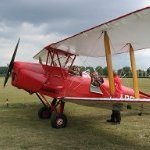
Build of my pup is done! Basically OOB, with nylon monofilament, Ezline for rigging with DIY buckles and rings. Paint used is a local vendor of hobby paints, Armored Komodo brand. Link to the actual build is here, Now on to the pics5 points
-
Friday is upon us....the Icehockey World Cup is also upon us and me being me means I will be watching lots of hockey which might impact negatively on me builing stuff Go Team Finland!!!! but I have an update for you. Closing the pit... Hmmm...I need to make the nose cone fit better...thst means a weee bit of putty. Then a bit of drybrushing. Next it was time for the HUD, you get to choose between a PE and a plastic HUD the PE always loos best but is a tad tricky. After a bit of wrestling and having small pieces of acetate fly off in to the infinity I finally had the glass put in and the HUD painted. Interesting that there is a piece of acetate covering the lens. To make life easier I cut of the tab in the windshield And glued it into place. A nasty seam to the nose cone And the canopy got put in place temporarely for the paintjob. Painting draws closer.... Cheers!5 points
-

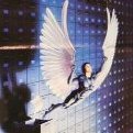
Bandai 1/48 Snowspeeder
Model_Monkey and 4 others reacted to LSP_Kevin for a topic
More out-of-practise modelling from me, as I continue to make mincemeat of the world's easiest build! The wee Snowspeeder has just received a panel line wash: This is actually the second attempt at the panel line wash, as my first attempt with oils (my usual approach) all but wiped right off completely during clean up. I had to fall back to some AK Interactive Panel Liner, and even then, it's still pretty patchy, and I'm far from completely happy with it. Even so, I think it'll be fine as the basis for further weathering. I must remember to paint that panel in the nose, however! Kev5 points -
Back to the paint shop. Time was spent to reinforce contrast and adjust tonal balance. Mostly done with brush and oils. Always in the build-up mode. The result after a few hours work. First attempt at depicting the oil spill from the left side window (an idiosyncrasy of the early Hawks) The dentist’s view! To be continued…4 points
-
I blew out the primer. Metallic. There are, of course, nuances that I did not consider when switching from 32 to 72. But we learn from our mistakes. And a couple of annoying places revealed, need to. fix4 points
-
Getting ahead of myself a bit here - work on the tail landing gear is some weeks away at least. But I did want to fill out my 3D print order with it. It has come to my attention that the wheel I modeled in Rhino might not be accurate. And I think that is right. look at this photo, from the KD431 walk-around on LSP: I have some reason to believe that is an authentic Vought tail wheel and not some unauthorized replacement. Look at the six thin ribs, and compare to what i had modeled here: OK I think the six holes are wrong. So I Rhino modeled two different wheel/tire combos - one with the thin ribs, and one with the dust covers: I could go either way. I see period photos where it appears the dust covers are in place, and also not in place. Either way, I am going to have to somehow add in the tube stem, and if I go with covers, I will drill a hole in one side to allow for same. OK, on to bigger fish!4 points
-
Getting ready to prime the interior. The PE set is 'old school' with the film instruments, so, certain parts have to be painted first and then the back of the film painted white before completion. Slowly but surely. I had to clean off part of the model desk for Tuesday. We had our younger grandson (2 yr), he likes to sit up at my model desk and 'fix' his little diecast airplanes. Of course, he likes tools and will 'fix' anything including the Tonka type trucks he plays with in the garden. He even brought some of his tools along. One of his electronic type toys came along because he had faith that I could fix it. And yes, I got hugs and joy because I did fix it.4 points
-
I’m not sure about the AVG but on the RAF Tomahawks, yellow tips only on the side opposite the pilot.4 points
-
Hi all, I only had a few hours this weekend, so not much progress was made. I have covered the cockpit with a layer of Future, to prepare for wash & decals. I have painted a few switches and buttons, different colors based on the reference photos. These will be installed at the very end when the cockpit’s finalized with wash and decals. I have started to add decals to the side panels of the cockpit. In the next photo you can see the surface texture of the cloth covers and added decals to simulate the seam lines. For the seam lines I have used ANYZ 1/48 Universal labels and stencils set. Here’s a photo from the real cockpit where you can see part of these side cloth covers. Hopefully next time I can show better progress. Tomas4 points
-
One of 6 Polish C.Vs which served in 9th Sqn in 1919 until it crashed and broke the fuselage beyond damage.3 points
-
Once the Spitfire is out of the way I think that this will the next project while I am on a PCM roll. Cheers Den3 points
-

Is there a aftermarket 1:24 Revi C/12D gunsight available?
John Stambaugh and 2 others reacted to Model_Monkey for a topic
Hi guys, yes, as Greg pointed out I do intend to offer more 1/24 scale products including a Revi sight. Presently, I'm working on two different 1/32 scale Beaufighter observer's stations for the classic Revell kit, the first to be released within the next couple of weeks, followed by a 1/24 scale Shiden Kai cockpit for the Bandai kit, then a host of other projects. Timings have been badly affected by Covid-related issues but work is proceeding, just a lot slower than expected. I can move the Revi sight ahead of the Shiden Kai cockpit in the queue for a June release if your other sources don't work out. Generally, I'm not able to accept requests for new research and design projects, as Greg stated. The project queue is already full to overflowing. But there are indeed 1/24 scale projects in the queue. Cheers!3 points -
Get it cheaper off the publisher Chandos Publications … https://www.chandospublications.co.uk Rog3 points
-
Taking good shape, Tolga Just two minor details you’d want to correct: The two filler caps under the side window should be RED (fuel) in front and YELLOW or SILVER (oil) at the rear. GWH got it wrong with their instructions A noticeable difference between the P-40B/C and the later versions is the central seam visible under the chin. They’re very easy to correct and would add much to the finished model. Cheers, Quang3 points
-
Thanks Dennis! The drop tanks are definitely unique looking with the clear pylons. Thanks Vincent! Do it! I'd love to see a Vincent K build here! Thank you very much! Thanks Matt! Actually, I was more afraid of the bulkhead being knocked off during the fitting process. When it comes time, the bulkhead will not provide much of a glue joint unless I try to pre-apply some epoxy. The majority of the glue connection will be provided by the bottom and sides of the nose to the fuselage. Thanks Andy! Yeah, it's work but I'm enjoying it! I don't think it is a bad kit but it doesn't take much variance to throw off the fit if you are not careful. Thanks Michael! After the bulkhead was glued into place, I verified that the nose/engine was able to slide into place without interference. There are some slight overhangs that I'm hoping can be corrected with finger pressure during the gluing process. Bigger gaps will be filled with sheet styrene or sprue so that I can increase the joint strength as much as possible. The width of the nose section is a bit tight at the forward edge of the wing roots. It may be causing a bit of anhedral so some slight trimming might be necessary. After the test fit, the seam around the edges of the bulkhead were filled and cleaned up. I'm not going to bother doing any paint touch-ups now as it will be easier to do that after the fuselage camo painting is done. The stabilizer joints have been cleaned up as well.3 points
-
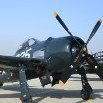
Here is my recently completed 1/32 Tamiya F4U-1a Corsair painted in one of Greg "Pappy" Boyington's purported mounts, BuNo. 17740. The Tamiya kit is an extraordinary state-of-the-art kit and doesn't need much to build up into an impressive model but I did take the liberty of adding a few aftermarket items: 1. Vector Resin Cowling 2. Barracuda Resin Wheels and Tires 3. HGW Fabric and Phototech Harness 4. Barracuda Cockpit Stencils 5. Montex Masks 6. True Details Resin Parachute 7. HGW Wet Transfer Stencils The complete build can be found here: The canopy is removable so that I can pose it in the closed or open position. I did not glue the wings into place so that transport would be easier. AK Real Colors acrylic paints were used for the exterior.2 points
-
I start building an interesting model from Ukrainian manufacturer "Clear Prop" in the 72nd scale. This is the first model of this domestic manufacturer, which I collect in general and the first in many years in the 72nd scale.. On the model itself I think there were great reviews, from myself I would add that very high quality casting even small parts (minimum workmanship) . The plastic is nice to work with, not brittle. Assembles perfectly at this stage of assembly. Variant of the Argentine Air Force number 607 . Started with the cockpit. I could not resist and added the wiring. The model is equipped with photo etching, which animates the appearance. Worked with the engine. Painted the cockpit and engine.2 points
-
Just put a big coat on, and go on endless bus rides, to nowhere.2 points
-
I've now rescribed some of the panel lines that weren't holding the wash, and reapplied it in those areas. Seems better now. Photos in the next update! Kev2 points
-

Zoukei Mura - Old Man Blog No.115
Rick Griewski and one other reacted to rafju for a topic
Up to this day, summary of the parts and instructions, waiting for the last one: The Old Man Blog No.116 - The instruction manual (Japanese version) for the SWS 1/32 “Bf 109 G-14/U14” is completed!! Part 1 | ZOUKEI-MURA (zoukeimura.co.jp) The Old Man Blog No.117 - The instruction manual for the SWS 1/32 “Bf 109 G-14/U14” is completed!! Part 2 | ZOUKEI-MURA (zoukeimura.co.jp) The Old Man Blog No.118 - The instruction manual for the SWS 1/32 “Bf 109 G-14/U14” is completed!! Part 3 | ZOUKEI-MURA (zoukeimura.co.jp) The Old Man Blog No.119 - The instruction manual for the SWS 1/32 “Bf 109 G-14/U14” is completed!! Part 4 | ZOUKEI-MURA (zoukeimura.co.jp)2 points -
Lots of great modelling going on here and lots of useful information for my future build. Cheers Dennis2 points
-
I reckon those old school laminated instrument panels produce the best results, personally. They can be a bit fiddly, though! Kev2 points
-
Looking fantastic ..! Gotta love those Air Superiority Blue Eagles ... -Gregg2 points
-
Edited some images2 points
-
Build is done! A preview of the finished kit. The rest of the images are posted on the Ready for Inspection site.2 points
-

THE SHARK HAS LANDED! Curtiss Tomahawk 112sqn RAF
Paul in Napier and one other reacted to quang for a topic
Thank you guys for your kind words. @nmayhew Haha Nick, incidentally I saw your Neville Duke WIP the other day. A great, detailed thread and also a superb read. It was very interesting to be able to compare approaches and techniques. Now back to the fray. Nothing spectacular happened these last weeks concerning the WIP because I was mostly concerned in doing something I have always neglected before: WEATHERING. For years I’ve read the magazines, attend the forums, study the videos, discuss about the current trends but I never put it into practice … …until now . I’m sorry I haven’t taken many pictures during the whole process because progress is very slow and the results not readily apparent, being on the discreet side of subtlety. Aside showing that our plane has been subjected to wear and tear during its (rather short) lifetime, IMO the final purpose of weathering is to add more contrast to the colours and the contours of the model and to make it more ‘readable’ while giving it more depth and life. It’s mainly a build-up process and like with every build-up, the issue is to know when to stop before going overboard Wing and cockpit floor assembly. The fit of the GWH is so good that the wing and fuselage can be finished separately and finally assembled without a joint showing. Stock seat with refined and beveled edges. Sutton harness is Eduard steel etch. Cockpit floor is treated with hairspray applied with a paintbrush. I added some Libyan desert sand next to the foot rests. More wear added to the walkways using oil paints. I gave a quick brown oil wash to the upperwing to unify the camouflage and deepen the contrast. Walkways and wing, different materials, different wear. Note the metal ledge bordering the linoleum walkways. Next time: the underwing and the fuselage. Questions and comments are very welcome as usual. Until then, keep well. Cheers, Quang2 points -
PCM Spitfire Mk.IXc
Tolga ULGUR and one other reacted to dennismcc for a topic
Thanks Mike, I forgot to add that every time I do something to this one I keep muttering about not forgetting to drill the gun camera and fuel cooler holes in the wing roots a simple thing that I have forgotten on other Spitfire builds so that also got done. Gun camera, taped over in this case. Fuel cooler And done Cheers Dennis2 points -
PCM Spitfire Mk.IXc
Tolga ULGUR and one other reacted to dennismcc for a topic
Some progress at last, I got around to changing the code letter masks to the correct ones and masking off the rear fuselage Sky band, the latter made me move the code letters forward a bit to fit the band in. They were probably in the wrong place to begin with but hopefully now they are correct. Then out with the airbrush and the yellow paint, and the roundel position and the wing leading edges were painted, so I can now position the fuselage roundel mask. Cheers Dennis2 points -
Time for another update! Even though it seems like I'm racing through this, it still somehow feels like slow progress. Anyway, I decided to experiment with using the kit decals for the panelling effects, and while they were OK, I'd definitely mask and paint them next time. For starters, the printing is surprisingly coarse, with the dot pattern quite visible close up. They're also quite thick, and I'm still trying to deal with some residual tenting issues around raised details. And the last issue, one of my own making, is that I misplaced some of the underside panels, creating gaps and misalignments along the way. I decided not to apply two of them at all in the end, as there was no way they were going down over the raised details in those areas (I did try with one of them). Here are the photos: I've started to weather the rear panel, ready to be inserted later: I've also started to paint the pilots, base-coating with Fire Orange from the new Infinite Colour range from SMS: They'll need another coat before I can move on. Lastly, I prepared the kit stand with a simple black-and-white finish: I should have taken that photo against a blue background, as there's no hope of seeing anything against a white one! Anyway, once I can get the decals to all fully settle down, I'll seal them in with a clear gloss coat, paint the dark nose panel (oddly missing from the decal sheet), and begin the weathering process. Should be fun! Kev2 points
-
Pacific Coast Models Hawker Tempest
Model_Monkey and one other reacted to dennismcc for a topic
Nearly there, the wing tanks have been giving me grief, though it's my own fault as usual, it took a while to get the clear fairing frame decals in place, then I had to paint the areas were I was short of one decal. Then I decided to dirty the tanks up a bit so I held the tanks with clamps on the clear fairings while I did this. Fair enough, it went well but when I removed the clamps I also removed the decals that I had so carefully applied, so out with the paint again, not a great job but it will have to do, it's shame as the PCM decals for the tanks are better than the HGW Wet transfer versions. I also decided to drill the wing and fit pins to the tanks to fit them to the wings rather than just glue them to the wing, it's not accurate as the fuel pipes were at the rear of the tank on the real thing but never mind. I don't normally do things under wings but the Tempest tanks are so much a part of the Tempest story that I had to fit them. I also realised that I had forgotten to remove the masking disc from the various underside lamps so it was nice to remove them and see the finished results. And the corresponding holes in the wing. Then the radio aerial, it is showing on the photo as black but it's steel in real life as I believe they were stainless on the real thing. And the gun barrels, for this I used drilled out plastic rod painted with metallic black. Test fit of a tank, not the greatest fit, but no one will see it apart from me, and you lot. And the IFF aerial, again painted with steel And the semi finished state it is in at the moment, I am rather pleased with the result as it looked a bit iffy if I would finish it at all at the start of the build. That's about it, I'm just waiting for the varnish on the other tank to dry before I can fit it and then I'll take some more photos for the RFI. Cheers Dennis2 points -
.thumb.png.64af68ce3763f9af8a91e71374ce741e.png)
1/48 Lockheed SR-71 A Blackbird undercarriage RELEASED NOW AVAILABLE TO PURCHASE
Gary Needham reacted to Ali62 for a topic
NOT LSP BUT IT IS QUITE BIG. The undercarriage is now drawn, needs to be printed and checked, then brass parts sent to casters. All being well and some design change you will be able to install the undercarriage after main assembly and painting of model, added to that a much stronger set of undercarriage.1 point -
 I'm the first to admit my ordnance recognition skills lag somewhat behind my aircraft recognition skills, and I wondered if the collective expertise here on LSP can help me? I have a Hasegawa P-47 that I want to finish as a British Thunderbolt Mk II of 79 Sqn. My particular subject is KJ233/NV:G of 79 Sqn in Burma, seen at 2:55 in this short film: https://www.iwm.org.uk/collections/item/object/1060025281 There are various interesting points, including shots of bombs being loaded right at the start. Can anyone identify whether these are British bombs, or US-supplied bombs? If the latter, I can use the items in the kit. It would, of course, be expected that the RAF supply chain supplied British bombs: but were the mountings, fusing systems, etc compatible or even common with the US systems in the P-47? Or would appropriate mods have been undertaken to the aircraft? Or did they use US-supplied bombs? I'll put my can (of worms) opener away now: any information would be appreciated, and as the title says, enjoy the video anyway.1 point
 -

HK B-17...C 5/4 sweating the metal
Greg W reacted to brahman104 for a topic
So I think I've come up with a workable solution for the actuators. With some rod ends from RB Motion that fitted nicely inside a brass tube, I figured I could use 3mm magnets in the actuator gearboxes that could provide enough "grab" to hold the doors in the open position, yet still loose enough to allow them to move closed. Not entirely sure it'll work yet, but I think I'm off to a reasonable start.... To give the magnets something to grab onto, I inserted a steel pin inside the brass actuator tubes. They can slide freely through the gearbox bodies. I just have to figure out how I'm going to mount them into the bomb bay now while still allowing them to pivot when the doors open. I luckily had a 3mm end mill to machine the recesses into the brass rod. I hadn't used the lathe and mill in well over a year, so it was really fun to get back into some good old fashioned machining. I could have 3D printed the gearbox bodies, but at least I know they won't break! Here's the actuator more or less assembled. You can see the steel pin which sits inside the brass tube which is attracted to the magnet. The pin runs the length of the actuator, so I can position the rod at at point. The end of the pin was ground off and a brass "limit cap" was soldered on which also contained the steel pin. I still need to add some styrene details to it, but that's pretty much what the 4 actuators will look like. Next up, I need to mount them in the bay and fabricate some brackets for them to attach to the doors. Stay tuned! Craig1 point -
ZM Henschel Hs.129B-3 pics
npb748r reacted to thierry laurent for a topic
This is very probably the price of the the original edition (that is OOP for more than 15 years).1 point -

1/24 Trumpeter FW-190D
adameliclem reacted to SimonCornes for a topic
Thank you guys! The reviews Ive read say it isn't a bad kit apart from the cowl hinge line. When I get it I'll give it the once over but Id say that my priority is the seat harness although at that scale lead foil, etc may well do the trick. Weighted wheels would be my next 'wish' and I'll have look at Peddinghaus. I've used him before for 1/16 AFV markings but, in my opinion, he's nothing like the sort of decal manufacturers we're now used to - crude by comparison really and you have to know what you're looking at as no guide as such but I'll see what I can see on the website. Thanks again Simon1 point -
Cleaned the wash,ready for flat varnish...1 point
-
evening folks & thank you got a bit more done, like finishing off the carb intake... ..this needs to be ever so slightly proud so that metal skins around it will sit flush with it - it will ultimately be painted as i can't really make it from metal and polish it (I did try..) ..this is done by marking the boundary with dyno tape and adding a very thin skim of P38 filler which is sanded down to the tape - hey presto, a great, proud edge to skin to.. ..the gun covers either side of this intake are being 3D printed, so in an idle moment I started on the gun breeches... ..these are PE and stock and are the Browning M2.. ..thankfully, very early in the build of the guns, I looked at my subject... ..now I did a couple of double takes, but there are no gun covers on that aircraft - just the central carb intake right? this is with the covers.. ..so that was news, and good news as skinning around all the humps & bumps would have been tricky.. it also meant I didn't need to make guns... ..as I wanted to get all the big ugly building on the fuselage done before I can start on the cockpit, I wanted to start the stabiliser.. ..I used plans to make my own drawing which was stuck to 2mm plastic card.. ..hopefully you can see the slots I need to cut in the leading edge to slide ribs onto.. ..the ribs were cut from thinner card and slotted into place and all the borders done in black sharpie so I can see where to sand to.. ..first gob of P38 filler.. ..after the first rough sand down to the rib outlines.. they are really only a guide.. ..final sand before final prime.. ..and the finished stabiliser - the intention being to cut away the front and some of the fuselage so they slot together.. ..working out the alignment... ..after dremelling away most of the 5 min epoxy in the joints.. ..and just in case you sit there thinking I don't regularly screw things up, this is the second time I had to chop it all apart, this time after filling & blending it, I noticed I just had it in entirely the wrong place - as you can see above, the elevator hingline should be a couple of mm behind the rudder hingeline - I had it waaay behind.. ..also notice the damaged tailwheel well walls where the CA impregnated foam is just too weak for handling.. ..finally in place and blended in - the filler acts as a base for the complicated one-piece metal fairing that goes around the joint.. ..also chopped away all the lower rear and rebuilt the tailwheel aperture with a sheet of formed plastic card.. ..the next thing to do before starting getting the cockpit together is the scalloped panels behind the rear cockpit glass... these were made from drawings interpreted from photo's and tape templates from the model itself.. ..I had read that these panels are NOT cockpit green, but olive drab (or camoflage colour if camo is used), so I painted them OD and added the pipe bases... ..and in place.. ..a dry fit of some components, the next stage of the build is figuring out how to detail the cockpit in a sequence that will work - a particular problem being the instrument panel, rudder pedals etc will need to be a free standing assembly coming off the floor I think as it's gonna be tricky to mount a crossmember to the sidewall carrying it all.. ..until next time.. TTFN Peter1 point
-
Some good progress on this one today. I managed to tidy up the damage I did around the rear cowl with some heavy applications of Mr. Surfacer 500, followed by clean-up with some cotton buds moistened with Mr. Color Levelling Thinner. After that, I could assemble the rest of the cockpit components and join the two hull/fuselage halves: I'm taking a lot of inspiration for my build from one that Jon Bius built on his YouTube channel. In that build, he describes how he left the black rear section off for the painting and weathering stages, and fitted it towards the end, so I'm taking a risk by doing the same: It'll be a tight fit, but I've deliberately not glued the two halves together along the back, so I can potentially pry them apart sightly to facilitate the process. Another tip I got from Jon's build is to use the 2-piece canopy solution (rather than the 2-piece all clear alternative), mask the inner clear piece, and then assemble them temporarily for painting and weathering: This can be popped off at the end, so that the interior frames and roof can be painted, and the masking tape removed. Jon even left his clear piece out, just like with the filming miniatures. I'll decide on that when I get there. Here are all the major assemblies after a couple of light coats of Mr. Finishing Surfacer 1500: The black areas were painted first with Tamiya Rubber Black. I've decided to keep the Mr. Surfacer as the base colour, as it's pretty close to what I was aiming for anyway, and will make a good base for the subsequent weathering. I've also decided to try the kit decals for all the panel variations, rather than mask and paint them, so the next step will be to give the relevant components a good gloss coat. But if you've built this model and used the kit decals before, and lived to regret it, please let me know! Kev1 point
-
I don’t know about the first photo but on the second one, it’s indeed a blue formation light on both sides of the fuselage. Same light on a P-40E Cheers, Quang1 point
-
I really like how the fasteners and things are finished. Keep on chugging!1 point
-
Lumber pad shaping sequence continued... Basic shape completed. Derek1 point
-
Ejection seat detailing sequence/progress. (Below) Liferaft Personal Survival Pack (PSP) completed and start of seat leather cushion. Seat cushion shaped and slot created (kit seat cushion shown above it). PSP and seat cushion assembled. The seat cushion has been shaped and scalloped to make it look used and sat on. Start of parachute pack. Test fit of parachute pack. Check fit of parachute pack, PSP and seat cushion. The parachute pack was covered in self adhesive aluminium foil (gas plumbers sealing tape). A single piece of thin copper wire was added around the parachute pack to represent the edge pack cover beading. The parachute pack cover material creases were impressed into the aluminium foil (which was the reason for covering it with foil in the first place). Using the same aluminium foil, pack cover closure flaps and opening elastics were fashioned and added to the parachute pack. The parachute was completed with the addition of a parachute pack opening rip cord cable. The assembled ejection seat Aircrew Equipment Assembly (AEA) and Survival Equipment assemblies so far. A parachute pack seat support has been added to the seat, which supports it as per the full size item. The square shaped grey plastic card is the start of the harness back pad assembly. Derek1 point
-
The instrument panel cowl needed some work as it was the wrong shape and had no (or incorrect) detail. An obvious feature not present in the kit cockpit are the cockpit warning panels which are in strip form on either side of the cockpit cowl sides, so I scratch built them. Below are some progress shots and comparison to another standard Trumpeter kit part for reference. The Cockpit Warning Panels (CWP) were built up from thin plastic sheet - I used the grip parts of the plier jaws to create a regular ridge pattern in the plastic strip. These ridges were then filed to regular stepped angles. These were then cut to the correct lengths and were glued onto thin plastic card, which was also glued around all sides. Once dry, the individual CWP panels were sanded down to the correct size and shapes. Some comparison shots of 'before' and 'after': The kit cockpit does not provide rudder pedals, so I made some. Below you can see where I have added a little more detail to the kit cockpit right console (anti-G valve and stop cock, light shroud and electrical panel). The left cockpit consul was altogether much more problematical! (see below). As can be seen, the throttle panel as supplied in the kit is positioned much too far aft. I could not live with this, as it positions everything incorrectly, looks wrong and will not allow other key features to be added, so some drastic rectification was required. I removed the throttle panel from the console and filed the corresponding vertical angled panel flush to form a single flat vertical panel. I then modified, detailed and re-shaped the throttle panel before I mounted it in its correct forward position. Once this was done, I could then fill the void below it with a plain panel, hide the fictitious shaped at the back of the cockpit side panel with a plain electrical flat panel and finally add scratch made throttle quadrants and AI radar controller plus a couple of other knobs and levers (these are key features which are missing from the kit). As the top of the angled cockpit seat bulkhead is a fairly prominent visual feature, I modified this area first to resemble more or less what would be expected to be seen in this area (see below). The top of the control column bears little resemblance to the real thing and is not angled correctly like it either, so I modified and detailed it to look something more like the way it should. Derek1 point