Leaderboard


Popular Content
Showing content with the highest reputation on 01/24/2021 in all areas
-

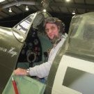
F-4E Kurnass 2000 1/32 Tamiya
Loach Driver and 17 others reacted to Peter Gregor for a topic
Hi, so another Israeli bird is out. It is an F-4E Kurnass 2000 number 650 from the Bat SQN, Tayeset 119. The F-4E kit from Tamiya is used as a basis. The building was quite comfortable, I did not encounter any major problems. I used the cockpit from Avionix, of course, supplemented with a modification of the Kurnass 2000 version, MFDs, few switches, and a new HUD were added. I also used the seamless intakes from RealModel and thanks to Miro Medzihradsky for the dimensionally accurate engine nozzles. The refueling probe and part of the decals from Isracast are complemented by Hebrew stencils from Skys Decals. The armor plates in the lower part are cut out with a plotter, the central fuel tank is from the F-4J kit modified to the IAF standard. What bothered me the most was the slatted wing, but I think that the result revived the model. The AGM-142 with a pod are from the F-16I kit, but it was necessary to enlarge the pylons because they were specially adapted for these missiles and I also redesigned the guidance part of the missiles. The outer pylon for AN/ASW-55 is from RealModel. The AN/ALQ-184 (short) ECM s from AMS Resin and the adapter for ECM and reduction for the Sidewinder to the AIM-7 shaft are homemade. The whole model is rescribed and riveting according to available materials. The wheels and arresting hook are produced by Eduard. MRP colors and Ammo Of Mig washes were used on the surface. The sources are from Isracast and Double Ugly Books. Thanks for all comments. Added pictures:18 points -

Italeri CF-104 Starfighter "Kicked up a Notch": KLP Publishing eBook now Available!
KiwiZac and 16 others reacted to chuck540z3 for a topic
Thank you Gents! January 23/21 A short update, but I think a very important one. The fuselage has been glued together and all gaps have been filled with CA glue and sanded smooth. This was tricky on the dorsal area, where there are 10 small square access panels that need to be rescribed after filling. Thankfully they line up pretty good, but that’s partly because the panel lines are so darn big! The Eduard exterior set has these little panels in brass to cover them, but since they are so small and curved, I left them off since I think they will cause more headaches than they solve. On the underside, I left off part C-9, so that I can install the main landing gear at the end of the build. Here it is dry fit to the rest of the fuselage, which is a bit of a mess just forward of it on the left. This must be a well-known problem, because Eduard also has a brass plate to cover this area, so I glued it in place and then sanded it to remove any sharp edges and help the paint stick to it a bit better. I also decided that since I will have an MN-1A bomb dispenser (modified SUU-21 dispenser) hanging from this part, I should have some extra strength here that is easy to glue to underneath, so I installed styrene strips that conform to the curvature of the part. Part C-9 will not only be an easy drop in, but strong as well, although the arrow head should not have a panel line through it. According to my Wingman Jari (Finn), that recess forward (left) of the brass plate should be filled. Consider it done. Thankfully the center line pylon that the bomb dispenser hangs from will cover this, so you won’t be able to see it easily. Moving forward from the center, I had a very hard time installing the front landing gear assembly, because it wouldn’t fit flush. At first, I thought it was interfering with some of the resin assemblies I installed above it, so I spent a very long-time trimming pieces and dry fitting, but to no avail. Finally, I shone a flash light from the back through the part C-9 opening and discovered the culprit! The port/left side of the gear bay was rubbing up against the gun compartment, which has nothing to do with all the resin I installed. After sanding the outside of the gear bay and the gun compartment, everything slid into place nicely, so here’s a tip for you who may have the same problem in the future. In all my frustration with this assembly, I forgot to install the clear light F-5 from behind in that little hole on the left. Dang! Now I’ll have to install one from the outside the hard way. Recall that I had a lot of gaps to fill and detail to add in the front cockpit area. All better now, but a lot of picky work to fill the gaps, and add a styrene strip behind the cockpit missing on the kit parts, without wrecking the delicate detail of the avionics bay. This time I didn't forget to install the little light at the top of the fuel cover! I also created a new avionics bay cover hinge out of modified styrene I-Beam, instead of the brass one I had before. While the brass hinge would have worked, the styrene one is much more flexible and easier to work with, and allowed me to scribe hinge markings on it which you can’t really see very well in this pic. Here is the hinge from the rear, unpainted so that it will stick to the cover. I sanded a slight groove in the sill for it to sit in, so that it will be an easy drop in at the end of the build. Here is the hinge glued to the cover and dry fit with tape, which shows the hinge detail a bit better. From reference pics this door opens about 80 degrees, while the canopy is closer to 90 degrees, so I can adjust the angle accordingly when I glue it in with Gator glue, that is flexible and easy to clean up with water. When installed permanently, I will add additional wires that go from the cover to the bay itself. I end this post with a problem to fix. The windscreen is too wide for the fuselage and based upon a quick review of other builds, I’m not alone. After painting it underneath, I installed it a tiny bit rearward to help with the width, since the further you go back, the wider the cockpit sill. I also squeezed it slightly, being careful not to overdo it and risk cracking it. I plan on sanding the edge of the windscreen to narrow it, rather than just add filler that will look wrong. This in turn will erode the fine fastener detail on the bottom, so I plan on redrilling some of these recesses to recover what I sand off. For the CF-104, the front infrared sensor at the front of the windscreen was removed, which was another pain because it's hollow and needed to be filled. When I finish that, I will add the brass side rails to cockpit sill that will eliminate the square opening in the corners. I hate it when clear plastic parts have challenges, because the plastic is so brittle and hard to work with, but I’ve been to this movie before and maybe I will have a happy ending once again? I also crashed and burned with my Kitty Hawk Harvard build that gave me fits with the canopy, so wish me luck! Cheers, Chuck17 points -

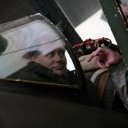
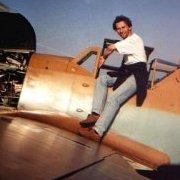
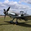
Bf 109G-10/R3, W.Nr.130297 10./JG 51
109 and 14 others reacted to Miloslav1956 for a topic
Hasegawa 1/32 model Eagle cals, Aires wheels, exhaust & cockpit, AMUR propeller & scoop, painting mask homemade, all colours MRP. reference:https://www.forcedlandingcollection.se/LWe/LW136-Bf109.html15 points -

Strike Wing Mosquito FB.VI
D.B. Andrus and 10 others reacted to John1 for a topic
Calling it done on this year long project. Kit is Tamiya's magnificent (dare I say the best scale aircraft model ever released) Mossie, with a boatload of scratch built details (I think I put over 200 extra items into the weapons bay alone), Barracuda cockpit decals and other bits, AIMS 100 gal slipper tanks and Avieology decals for No. 333 (Norwegian) Squadron. Thanks to everyone on this site who patiently answered my hundreds of questions and provided additional information. Here's the real thing, it matches up very well with the one photo available of KK-Q.11 points -
OK - some pix. Bear in mind this has involved some major modifications so I'm very pleased with how well everything lines up! Assembly done with Revell Contacta (the one with the needle applicator) for maximum strength, and minimal shrinkage. Aires cockit tub bonded with thin superglue... I've just spent 5 mins with some sanding sticks and everything mostly blended together beautifully! Now, that emergency canopy release - here's a photo of the real thing - printed out and bonded behind the clear cover. Looks OK I think - remember, this is only about 4.5mm diameter... And some initial assembly of undercarriage assembly halves, and under-nose intake. Note that the oleo section on the nose leg has been separated - this will be shortened later to improve the 'sit' of the final model: Back later, perhaps... Blue skies! Iain11 points
-

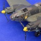
1/32 Revell Me 262B-1/U1 Nachtjager
Paul in Napier and 10 others reacted to Thunnus for a topic
Some of the external bits temporarily placed using bits of Blue Tack...11 points -
1/32 Revell Me 262B-1/U1 Nachtjager
Paul in Napier and 10 others reacted to Thunnus for a topic
The rest of the stencil decals have been applied and now it is time to give the model a dirty wash. As usual, I am going to make my washes using pastel chalks and water. I am making two washes... one light beige for the undersides and a dark brown for the uppers. A drop of liquid soap is added to the mix to help the pastel particles to suspend and not sink. The undersides are done first with the beige color. The wash is brushed over all of the raised and recessed details and allowed to dry. The top sides are given a dark brown wash. I usually work in sub-sections to make sure that the wash process is complete and uniform. The brown shade was chosen to provide contrast with the light blue upper camo color and add a dirty tinge to the exterior. I thought a black wash would be too stark.11 points -
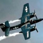
F7F-3 Tigercat - BuNo 80405 - VMF 312 MCAS - El Toro, CA 1946
R Palimaka and 9 others reacted to Out2gtcha for a topic
MLG bays are done, the nacelles are fully and permanently attached, and the firewalls are fared in to the top of the wings: While not perfect, the fit of the nacelles to the wings was pretty decent, and will only requite a minimum of filler or corrections: The tops of the nacelles was very carefully aligned with the panel lines on the tops of the wings, and thick CA was applied to fill any major gaps. No need for anything fancy here on top in this section, as you will see why later in this post: I ended up taking a series of finer mesh sanding sticks to the top nacelle area as to get the transition as smooth and step-less as possible: Taking a very small page out of Peters book, I used the tape flap method to apply some contact adhesive for the upper PE wing/nacelle pieces. These large PE parts have raised rivets where required and will negate any need to fill or re-detail the area where the wing meets the nacelles: I dont have any pics of the finish product yet, as by the time I used some balsa wood blocks to smooth things down, then applied thin CA to any edges that needed it, it was pretty late. The landing gear SHOULD be next, but I ran out of the correct size of stainless steel tube I need for the front oleo strut, so I placed an order for some more tubing. I will have to move onto other things in the mean time, so my plan now that I have the large upper wing PE parts in place, is to do some smoothing and finish sanding on the whole exterior, as I havnt really touched that in years. I need to apply an overall primer coat of white to see where I am at in regards to what I need to sand in order to apply the rest of the smaller PE parts. Cheers!10 points -

RAF FG.1 XV571 WILD HARE Phantom Conversion
Seversky and 7 others reacted to Anthony in NZ for a topic
Here we are at the intakes...did I mention this is a massive job???LOL. But I think if you see how I have tackled it, then it might make it a little easier and quicker. As I say there are probably other ways, but this is just how I have decided to go about it. Both top vent boxes are done (and match-phew) but I still need to add the louvers. But I am just finishing up the lower ones before I tackle that. I have taped them to the WH resin fuse to see where I need to be as I know this area is going to be a mess due to the fact this area was widened too much. I can slowly see the more accurate 'coke bottle' shape starting to emerge However you will start to see the issue between the resin fuselage and accurate (I believe) intakes. Notice the 'dip between the 2? The actual shape is somewhere between the two here it is close up Interestingly what I can now see is how the Spey engine thrust line must effect the intake trunking. and structure shape, and why the shoulder is higher at its junction with the upper fuse spine area on Brit Phantoms. I will address those shapes in another post As always thanks for tuning in Anthony8 points -
1/32nd scale Avro Shackleton - scratchbuild project
Tony T and 7 others reacted to tomprobert for a topic
It's been a while since I've done any work on this, but had the wind in my sails the other day so decided to get the engine nacelles finished off. I made some radiators and oil coolers (got carried away and didn't photograph these) and added these to the interior of each nacelle, before adding the 3D-printed engine fronts. A quick lick of filler to blend it all in and some sanding, and job done. Apologies for the poor lighting in the pics - these have been taken in the kitchen on my phone and the light was fading fast - it's too cold outside to set up the camera properly (this thing is so big and can't fit anywhere else other than the patio!) and there's snow forecast here tomorrow so I took my chances... I'm rapidly approaching the point where I can begin adding the surface details - I've been doing a remedial work on the wings and wing roots (as can be seen by the filler) and these areas, as well as the nacelles, will get a fine wet sanding and then a shot of primer before I can commence on a mammoth scribing session. A few more bits and bobs to attend to first though, but the main construction is more or less done now. All the best, Tom8 points -
For my own amusement as much as anything else I've been comparing the three Tiger Moth kits which are now available. I thought I'd make a running thread of my musings on various aspects of the three but please feel free if inclined to add observations, comments, questions or ribald humour! Part 1 - THE KITS: The oldest of the three is the Matchbox one, first produced as long ago as 1978 in multi-coloured plastic (why?) then latterly re-boxed by Revell in 1997 in a light grey plastic: Matchbox/Revell is quite a mouthful and too much typing for me so from now on I'll call it Revell. Only last year Silver Wings picked up the challenge in what appeared to be a gap in the market given the venerable age and increasing scarcity of the Revell kit. The Tiger Moth is very much in line with the type of aircraft that Silver Wings tend to specialise in so fitted the bill very nicely. A little persuasion from LSP members added to the chances of its issue: And then, completely out of the blue ICM announced a new Tiger Moth kit which has come out very recently indeed. ICM are the emerging player in 1/32 scale aircraft, we were all stunned and delighted by the Gladiator that they produced last year, so a new Tiger Moth was very welcome: BOXES: It's worth mentioning the boxes, and indeed the box art because in each category one is notable for all the wrong reasons. The villain in box design is the Revell one, an end-opening box which as a storage box whilst working on the kit is as much use as a chocolate fire screen. The hero is the ICM box, it's the type we have come to expect from them of a cover lid lifting off to reveal a stout box which opens from the top and closes securely. ICM can't rest on their laurels though because the box art isn't that good, especially the representation of a Tiger Moth being flown solo from the front cockpit.....it doesn't happen!! MATERIAL: Both the Revell and ICM kits are injection moulded plastic, the Silver Wings resin with some photo-etch. COSTS: Most people wanting a Revell Tiger Moth will search on eBay and as we all know prices there can fluctuate wildly, a recent search showed kits available between £25.00 and £70.00. Silver Wings kits, being short-run and resin are always expensive, slight variations can be found but typically they are around £120.00. The brand new ICM kit works out at about £35.00 from suppliers such as Hannants. WHAT'S IN THE BOX: So what do you get for your hard-earned money in terms of bits of plastic (or resin)? Five sprues with the Revell kit which includes two aircrew and a mechanic (not very well done I'm afraid), but also floats should that "float your boat" and an enclosed canopy if you want a Canadian version. Lots of bits (I haven't counted them but some smaller ones duplicated) giving a high level of detail. For example, a one-piece mould in both the Revell and ICM kits of the main undercarriage structure comprises five pieces in the Silver Wings kit. Just three sprues in the ICM kit, the most notable part is the lower wings and cockpit floor structure moulded as one, therefore setting the lower wing dihedral. More about that in later additions to the thread. INSTRUCTIONS: Wide, wide variations here! All are A4 size. The Revell one: Compared to the Silver Wings ones: The main problem with the Silver Wings instructions is that apart from the PE, there are no part numbers showing allocation positions so the builder is entirely at the mercy of the clarity of the illustrations. Experience shows they don't always work! and the ICM ones: I know which I prefer! Enough rambling for today, more diatribe downstream!!7 points
-
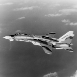
Test Build: 1:32 Flying Start Models Tornado F Mk.3 Conversion (Revell base)
Coneheadff and 6 others reacted to Iain for a topic
Whilst I'm here, the intake trunking has been taken out of the airing cupboard for a coat of looking at, and a bit of sanding. Looks crude after three dips (it's household emulsion paint, so it will be) - but sands easily and should give some nice smooth trunking: Sprue handle is a press fit into a previously drilled hole - stops me getting too messy whilst I dip the part. And the important bit - a little sanding to be done later: Making good progress now - may have a full airframe by next weekend! Stay safe! Iain7 points -
Found this on a local auction site, bid and held breath. The intake trunk was already glued so low asking price, I got it for € 40 including shipping. Now on the hunt for Big Ed’s set for this one...7 points
-
As promised more photos with the salt removed. I went with MRP M495 light grey thinned with around 70% lacquer thinner to get a translucent finish. That worked out okayish. I'm using a cheap salt mill for this purpose and its advantage is that it creates a lot of different grain sizes leading to random patterns. Its disadvantage is that it creates a lot of different grain sizes. You can see that on the port wing with the large dark patches where big grains covered the surface. There's still so much to learn! Adding the tip tank brings a whole lot higher contrast which tones down the problem on the wings - at least in my perception. The macro picture is unforgiving as usual and shows quite a lot oh salt residue in the panel lines. Even though I wiped the whole model with different brushes and even flooded it with water. But overall I'm quite happy to get closr to the finish line Next up is a flat coat to prepare for a grey oil filter and than it's "just" adding the small bits and bobs.6 points
-
Just picked this up today, first plastic to appear since the incredible 1/48 GWH Su27. And 20% off; how could I say no? Recently I've got a thing for 1/350 pre-Dreadnought BBs and IJN CVs; currently stalking a reasonably priced Kaga, not easy let me tell you. The Tsesarevitch was a French-built Russian BB, with a tumblehome hull, which looks exactly like a French baroque bombe chest -- what a coincidence. It was sorely tried by the Japanese and of course the worst abuse came from its owners, but it managed not to sink, only to be scrapped after the revolution. Lovely model, finely detailed, with all the PE included by Trumpeter, who truth be told seem to set their A team to making ships.6 points
-
Priller Double Thriller Part 2 - Trumpeter Bf 109 E3 1940 Complete
themongoose and 5 others reacted to Panzerwomble for a topic
@MikeMaben @Gazzas Thanks for the thoughts and pics. Just goes to show "what RLM says on page 435..." and what happended in the field can be quite different Not my area of expertise at all, and TBH I don't even know if it is pictures of the same aircraft ...ie I've no idea if he was shot down at all that summer . It looks to me that the amount of camouflage was added to as the campaign went on but his is purely my guess . It is a pity he didn't live longer , he died just after advising on "The Longest Day " but agree he probably had some great stories to tell . BTW your comment on another thread about "no one left alive who ever saw it for real" resonates with me Mr M Anyway back to the show .... Cockpit and engine mostly done , ready for zipping up tommorrow hopefully . Trumpeter colour instructions are vague , so making it up to a degree ( with the odd image search for 109 cockits) as we go, throwing airscale decals at it for good measure . Seat will go in towards the end , so I can mask it up easier .6 points -
6 points
-
6 points
-
1/32 Revell Me 262B-1/U1 Nachtjager
Pastor John and 5 others reacted to Thunnus for a topic
The wing roots have been set up for hairspray paint chipping but it didn't work out as well as expected. I should have learned from my Bf109G-14 build that mottle camo patterns and hairspray aren't a good match. You really need a uniform paint layer on top or else the chipping will just propagate around the areas where the paint is thinnest. I stopped after I started to notice this pattern. Wing crosses have been masked and painted. The fuselage crosses and tail swastikas were painted next. I'll let this dry before I paint the aircraft WN code on the tail, which will be the last painted marking. The rest of the stencil decals go on next.6 points -
5 points
-

HK B-17...C 5/4 sweating the metal
Starfighter and 4 others reacted to brahman104 for a topic
Thanks Terry! I'd put off doing the tail wheel for a long time as I wasn't really sure how to do it, but eventually it came together Agreed, there's lot of little sub projects going here, the question is: Will this year be the year we see them all come together? I sure hope so! That's certainly the plan Matt, she's putting on weight at a rapid pace these days! Thanks Tom! I really love working with brass, and parts can be as simple or as complex as you choose to make them. Give it a go, you won't regret it! It certainly is Mark! Another small update, but one I'm happy to have done. My order of scale hardware arrived from the States, so I disassembled the gear in preparation for painting. Nothing fancy here, just primed and painted aluminium, with a little bare metal foil for the strut and some DDG to break up the colour on one of the links. My retract screw looks much better with a wash. I also found a resin electric motor from a verlinden workshop set so that became my retract motor, with a little more creative painting and some wiring, it should look the part! Here's how it looks so far: I've also been working away at the shroud that sits partially around the tail wheel. A couple of years ago Tim (Wunwinglow) sent me an assortment of resin-machinable blocks. I always thought I'd find a use for them one day and today was it. Taking the fuselage contours from the tail wheel cutout in the fuselage, I cut, sanded and filed a male profile to form some litho plate over. In hindsight, I should have just used this to vacuum form the piece over, but I'd been reading Gerald Wingrove's "The Complete Car Modeller" over Christmas and wanted to have a go at forming a complex shape in metal. Firstly, here's the "buck" I then took two roughed out pieces of annealed litho and, working one side at a time, firstly creating folds with pliers, then working out those kinks with the hammer, started to coax the metal to my will.... After a few hours, I had something that looked pretty close. Still needs work, but you get the basic idea! At least the #8 bulkhead is back in place. Time to make that toilet I think! Cheers, Craig5 points -
Stage 'The Next' - missile fin cut-outs. I had an idea - strange, but true... The layout/spacings for the holes mirror those in the front insert so, I thought, put that on the scanner, scan, then mirror. Print out on paper, trim to size and we'd have a template. Simples! This is the mating surface of the front fuselage insert/3D print: And the scanned/mirrored/printed template. Positioning is straightforward - align centre - then rear edge of second slot from rear lines up with panel line - see arrow. I've scribed through with a sharp blade, so next I'll cut out the slots. Iain5 points
-
1/32 Revell Me 262B-1/U1 Nachtjager
Pastor John and 4 others reacted to Thunnus for a topic
Thanks Matt! No particular reason... just the way that I learned how to do washes and have never felt the need to try anything else. It's simple, easy, cheap and effective. Checks all the boxes for me. The remainder of the wash has been done.5 points -

F6F-5 HELLCAT 1:24 AIRFIX
phasephantomphixer and 4 others reacted to spartacus2000 for a topic
Hello everyone, little update (busy working week so little time to model) Air intake and small finished parts now I have to move to the carburetor and accessory support area.5 points -

Italeri TF-104G Marineflieger - final struggle
Chris Wimmer and 4 others reacted to Fanes for a topic
How do you like your zipper? - medium rare or well done? I like mine salty! Ready for salt fading with a light grey which was already applied and is drying right now. More photos will follow tomorrow.5 points -
None at all. Superb fit and clever engineering. struts were easy. Cabanes to fuselage, then wing on, Then each outer struts pops into its recess as they are springy. You can even plop the wheels in after the spats are painted. Simples. Loads of fun, honestly.5 points
-
5 points
-
Bf 109G-10 Erla, 3.JG300, Prague-Kbely,May 1945
Nikola Topalov and 3 others reacted to Miloslav1956 for a topic
My first finished model in this year. Revell kit 1/32 Aires cockpit, Eduard wheels, HGW riveting set, wet transfers, seat belts, Barracuda exhaust & decals Montex mask, All colours MRP4 points -
Cockpit plus engine bay are now essentially complete. Started work on the empennage and the various filler pieces that complete the fuselage. There are separate sections that drop in for the section in front of the vertical tail (so you can do different drillings for the different possible antenna combos) and for the section of fuselage that contains the rear LG. The latter is notionally to allow you to switch back and forth between gear down and gear up, but it's convenient in that it allows you to build and paint the rear gear completely but not install it until the fuselage is fully painted. With any other kit brand, there would be issues around these parts not fitting perfectly and just adding sanding/filling/fitting chores. With Tamiya, they just fit in perfectly and seamlessly. Anyway - here are some up to date photos of the engine etc.4 points
-

1:32 scale Ansaldo A.1 'Balilla'
geedubelyer and 3 others reacted to sandbagger for a topic
Hi all, I've now fully rigged the wings. This includes 'twin' flying and landing wires, cabane and interplane incidence wires and two bracing wires from the upper wing into the engine bay. The only wires not fully connected are the two drift wires from the rear spar of the upper wing. To avoid damaging them, they will be connected to the radiator area later in the build. For the same reason, the moveable aileron control levers in the upper wing will be connected to their control rods later in the build. Now it's onto completing the tail unit before tackling the inserts between the flying and landing wires, Mike4 points -

Which Tiger Moth kit? Part 11
Landrotten Highlander and 3 others reacted to mozart for a topic
Part 2 - FUSELAGE The Silver Wings fuselage halves differ from Revell and ICM in that with the former the nose section forms part of the fuselage whereas in the latter two it ends at the firewall. This has major advantages because, as Kev found out with his RAAF Air Ambulance conversion where he's using the Revell kit, attaching and lining up the engine bearers, the engine and the upper cowling can be tricky. Get it wrong and the whole of the nose section can look like it's been through a few rounds with Tyson Fury (insert your own choice of heavyweight boxer here!). Other less obvious external differences include the treatment of the area below the forward cockpit where the control horns for the rudder bar project, see below: The Revell kit ignores it completely, it just ain't there! The Silver Wings kit provides a slot and PE strips which you bend at an angle as the shield, and the control horns which you build into the cockpit framing. The ICM kit has the shield moulded in position but instructs you to drill two holes from the inside and secure the control lines early on in the build, ie no control horns showing. This is a compromise which can be easily overcome. ICM's is the only kit which includes a blind flying hood to be fitted aft of the rear cockpit.....Brownie points there! BUT whilst doing their research they have omitted the rubbing strips fitted below the rear cockpit which are there to avoid the thick rubber bungees from the hood ripping the fabric of the fuselage as the hood is pulled forward and backwards: On the other hand, Silver Wings have included the rubbing strip (Brownie points!! ) but no hood! Can't have it all I guess. Whilst looking at this picture, note the baggage area aft of the rear cockpit. Revell acknowledge the existence of this area with an engraved line. Silver Wings have moulded catches and a PE strip for the hinge at the top. ICM similarly have moulded catches but their baggage door is slightly proud of the fuselage surface. It isn't: Those catches Kev are fiddly to reproduce aren't they if you're using the Revell kit?! Just visible in the picture above towards the lower right corner is a green "bolted attachment". The vertical bolt secure the rear part of the wing to the fuselage. Silver Wings is the only kit which features this item, so more scratch-building Revell and ICM!! Notice how smooth the fabric is in these close up pictures. The ICM kit surface has a slight "grain" to it, I don't know whether this is an attempt to replicate fabric covering, and it will soon be lost under a coat of primer and top coat, but it really isn't necessary anyway. Moving to the aft end and the area of the fuselage where the cables for the elevator lines run: The Revell and ICM kits will have you drill these points; the former gives very precise dimensions for the correct position in the instructions, the latter drilling points are marked on the inside of the fuselage so these need drilling before halves are joined or else you're scuppered. The Silver Wings kit has small "fairings" moulded in place. They may have been on the Tiger Moth they used and measured but I can't remember noticing them before on the many Tiger Moths I’ve seen. Shooting right forward finally: the lower location points for the cabane struts! These really are horrible great square seats on the Revell kit moulded onto the fuselage, easy enough to streamline though. The Silver Wings rendition is much better, but interestingly they form part of the cabane strut on the ICM kit, not part of the fuselage. Enough for today! Part 3 moves to inside the cockpit.....a can of worms!4 points -
Ahaa, I did the same thing for my Mc200 (on the SOD). Yours look better.4 points
-
Lights on ...4 points
-
Spent the afternoon bringing the work I've done so far together. Have I mentioned how good the engineering on this kit is? Despite all the extra stuff I've stuck on, everything pretty much fell together. The tolerances in some places are so tight that I had to scrape paint off to get things to fit fully together, but other than that no real issues at all. I should finish assembling everything fuselage by the end of this evening. Then I'll need to think hard about how much detail I want to try and add to the landing gear and the gun bays. One downside to trying to show all the detail in this engine bay, even with the removable cowling sections, is that with the exception of those big aluminum pipes for the coolant system and a few bare metal linkages, pretty much everything is black, at least if you're going to be historically accurate about it. Black engine, black wires, black rubber hoses, black battery box, etc. It would be fun some day to do one as a hot rod - dream up a modern civil air racer scheme that could have a bright red engine block, chrome valve covers, braided stainless hoses, anodized fittings, yellow Accel plug wires, etc, etc. Have to give that some thought.4 points
-
Revell Focke Wulf Fw 190 S-8
Greg W and 3 others reacted to Chris Wimmer for a topic
Hi again! The space in front of the engine looks a bit empty as the Revell kit doesn't provide an oil tank. I found a couple of good pictures of a Fw190A-3 tank, not sure whether it's correct for the A-8. Anyway this is the point where my efforts on serious modelling come to an end: The kit engine is placed much more forward than the real one. So all I did was to create something that gives just an idea of all the things that should be there... More to come soon, thanks for looking in! Chris4 points -
4 points
-

Priller Double Thriller Part 2 - Trumpeter Bf 109 E3 1940 Complete
Chris Wimmer and 3 others reacted to MikeMaben for a topic
Acoupla more that might help PW ... Looks like standard cammo with mottle all over, including the wingtops. hth4 points -

First Build of the Year FW190 A-6
F-4Phanwell and 3 others reacted to Greif8 for a topic
Now some mid-distance and close up shots. Ernest4 points -
S H Tempest VI
Derek B and 2 others reacted to Nighthawk Calling 1 for a topic
Hi to you all I've been here some time hiding in the shadows and this is my current project Special Hobbies Tempest VI. After a long time away from the hobby and two false starts, one made it to the SOD but the other ended its days in the bin. This looked a straight forward build in the box but she has fought back all the way, so decaling under way and most of the build done I thought I would share with you all, mistakes a plenty and almost a year in the making the finishing line is in sight.3 points -

B29 TIE FIGHTER
Alain Gadbois and 2 others reacted to SCRATCH BUILDER for a topic
So i have person over at the Art Station web site and they do some pretty cool drawings and he had one of a B29 Tie Fighter and thought it would be cool to do this in 3D. So here is the 3D work and now I am of to the printers!, I do have the engines for a B24 kit i hope to use.3 points -

Hawker Typhoon
Michael931080 and 2 others reacted to Finn for a topic
or is it a Tempest? Either way a nice look at the weathering: Jari3 points -
Priller Double Thriller Part 2 - Trumpeter Bf 109 E3 1940 Complete
themongoose and 2 others reacted to Panzerwomble for a topic
Greetings - Part Deux. For this I will be building the "inferior" Trumpeter kit .....although with a decent fit and parts count , PE, etc seems ok to me and it comes with a Priller scheme -BTW this comment is not an invitiation to explain how 3 rivets are in the wrong place please .... I'm having fun , don't suck the joy out of it for me ! Two LSP's in one year as opposed to one a year .... hmmmm am I turning to the dark side ... .? Why is that Pz Mark IV looking at me strangely from the shelf ..? So ...enough of my yacking ....rocking on....references ....sprues , & starting to put it all together . I'll be back later with pics when it's painted Pic of the real thing - 25 year old Lt Priller of 6/JG51 Summer 1940....there are pics out there showing different schemes as the campaign went on perhaps more mottling more yellow and the wings don't look to be splinter on some ....see what you think . BTW I'm digging the Raven with a Cold ... Probably what I'll go with , is that nose yellow ? This one a bit earlier maybe no mottling at all ? ...although contrast and tonality is such a sod with old B/W shots. Doesn't look splinter cammo , and has someone P/shopped the swasitka of the tail ?? The bordeaux was a good one . ...3 points -
Revell 1/32 Heinkel He 162
Alain Gadbois and 2 others reacted to Grunticus for a topic
In the last few days I have redesigned my modeling room completely. New bench, lighting, layout. Lots more space and light now. The drawers are not installed yet. As we all know no one can finish a half ready kit on a brand new bench (the F-84G, which gave me more grief and was set aside once again). So I’ll start a dual-build of two Bu-131’s soon. Today I did feel like finishing the He-162 first. Notice how I divided the stash left and right so it seems like a normal quantity The new setup: Base markings and Werksnummer have been airbrushed using masks cut with the Silhouette cutter. The rest will be decals from the kit. Sorry for the not so good focus, the new LED light gives my IPhone an issue with flickering shutter. More soon.3 points -

1/32 HK Models Lancaster B Mk.I Nose Art Kit RF128/ QB-V Victorious Virgin.
Uncarina and 2 others reacted to monthebiff for a topic
Working through the port side and added the ground position indicator and switch box along with some cabling in the navigators position. With a bit of luck the interior will be finished this week and ready for some paint! Regards. Andy3 points -
B29 TIE FIGHTER
Jim Barry and 2 others reacted to SCRATCH BUILDER for a topic
A bit of an update, I have about 95% of the items printed, just some small bits to do, at the moment my brain is fighting with my attention span on weather or not to do a cockpit, for now i am set on printing my bucks and pulling some clear plastic for the windows. Almost forgot, I know i should have a 4 prop blade but i had an old 1/48 B24 sitting around so I'm using that.3 points -
To help with my PCM Fabric wing Hurricane build. Cheers Dennis3 points
-
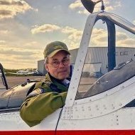
Received the Airscale upgrade for the cockpit, I guess i will need to remove the raised face of the original and make a small cut out at the top of the bas to slot around the range finder? I was also pleased how the pilot fitted together, I heard that it could be very difficult to get a fit - and started to prime - so whilst the build is going slow (and I'm in no rush) I've spent a lot of hours cleaning the fuselage - I hope I'm not boring you guys with my pictures. Take care and keep safe.3 points
-
Here is another pic: Jari3 points
-
1/24 Airfix RCAF Mustang IV…finally done
Greg W and 2 others reacted to R Palimaka for a topic
Thanks Michael! I've been at it for over three years as well, but it's so close to the end. I've run into a couple of frustrating little puzzles that have paused the build temporarily. I'll sort them out this week. As for the wheel bay, a better solution if you prefer, would be the 3D printed parts from Model Monkey. They are spectacular, and are designed to fit the Airfix Mustang. The detail is far better than I could ever have done, and will save so much time and cussing. You may have to wait a bit for them, but they would be worth it. https://www.model-monkey.com/product-page/1-24-p-51d-p-51k-and-mustang-mk-iv-wheel-well-inserts-for-airfix-kits In the meantime, here is the rough drawing I did. They are just hand-drawn and I've put a scale on them so you can confirm the dimensions if you print them out. I can send it to you in an attachment to your email. You can send me a message here at LSP. All of that stuff above in place: Richard3 points