Leaderboard

Popular Content
Showing content with the highest reputation on 11/29/2020 in all areas
-
Thank you chaps - very kind Hi Alain - thanks - no, no clear finish, I almost want them to oxidise to give a bit of age to things Gotta call that out Ben - totally untrue! I have seen what you do and it scares me - you easily have this sort of stuff in your locker I thought I might change things up a bit having been in the 'pit for a few weeks (and while I search for pics or drawings of the ammo boxes / chutes...) so thought I might make a start on the lower wings. These are more simple than the uppers (no ailerons) so are better candidates to learn on.. .. I copied the techniques in the Alcorn book - they made it look straightforward ..first up make a brass template of the rib - thankfully these are constant chord across the span until it gets to the tip.. the holes they are pinned through are the centrepoints of the two tubular spars and match the mounts on the brass tube fuselage section... after making about 30, they are put together as a laminated block (using broaches to align them), clamped and finished to all are identical.. as the book says, they were taken out and 'shuffled' a few times to get them equal.. ..i created a drawing of the wing with the outline & rib position marked and then stuck lots of little plastic 'U' channel strips where each rib meets the leading edge. The leading edge itself was a bit of half round plastic strip.. ...cut the tip shape from black plastic card so I can see the midpoint during sanding later and stuck those to carbon rod spars.. ..also made a jig for each wing so the assembly is flat & true.. ..started adding the ribs having reamed the holes to fit the spars as a tight fit.. ..there is a loose rib yet to be attatched at the root so the root rib is double thickness.. ..added the ribs to the tip as blanks and sanded them down, also added a folded litho trailing edge for a nice crisp edge.. ..added lots of sheet strengtheners - even with these the wing doesn't have a great deal of torsional strength against twisting, so will have to watch for that.. ..also added mounts for interplane struts and rigging... just thick 3mm card & brass tubes for now ..then realised I had not allowed for dihedral (doh...) ..so I put a slit in each spar and built a jig so I could crack them and CA at the right angle... once that was done I added a brass rib at the canted angle and backfilled with CA to surround the cracked spars - all seems strong enough thankfully.. ..and now I have started experimenting with scoring ribs into sheet with a ballpoint pen in order to skin them... I will most likely do one big skin and wrap around the leading edge.. ..this is all uncharted territory for me, so we will see how it goes TTFN Peter14 points
-

1/32 Revell Me 262B-1/U1 Nachtjager
Paul in Napier and 9 others reacted to Thunnus for a topic
I know I've posted a lot of build updates this weekend. That's what happens when normal Thanksgiving activities have been cancelled and your adult children have elected to stay at school instead of coming home. I actually spent most of today putting together the HGW seatbelts. This is a two-seater so twice the fun, eh? Although I love them and use them on most of my builds, I'm still of the opinion that the HGW harnesses are a bit overscale. I wish they were consistent and made the harness attachment loops (Part #6) overscale. They are way too small for me to effectively use. Instead, I looped copper wire around a small drill bit and cut my own, larger attachment loops, which were attached to the seat prior to the seat belts. HGW uses a fabric material that is pre-printed in the appropriate color. Make sure you take off the backing before using. I like to crumple my belts prior to assembly per the instructions to loosen them up a bit and add some irregular wrinkles and bends. A few hours later... I have two sets of assembled harnesses for the Nachtjager. Attachment to the seats was accomplished in two stages. The lap belts were glued into place using dots of CA glue. The belts were then given a clear coat and a wash to bring out some of the stitching details on the HGW belts. I then attached the shoulder belts and repeated the gloss and wash. A flat coat seals the deal and the seats are done. I can now glue the seats into the cockpit and get some shots of the nearly completed cockpit in the light box.10 points -

Hurricane PCM 1/32 Douglas Bader
FreightDog and 8 others reacted to X15 for a topic
Hi everybody, For the Battle of Britain 80eme aniversary i buit this Douglas Bader Hurricane from the Pacific Coast Models kit. Not an easy kit !! Paint with Tamiya and Gunze and oil paint weathering. X159 points -
Something has to tow the birds when they break down. I did it, I finally did it.......I left home and faced high temperatures and hot wind (no I wasn't talking!), took a bus and had to walk and then ascend 2 flights of stairs. TWO FLIGHTS!!!! IN THE HEAT!!! IT'S HOT!!!! But I made it. I found and paid for it. Then I decended TWO FLIGHTS of stairs with only gravity and teeth gritted determination to assist me. Here it is. In all it's regal spendour, a Lancaster cockpit. Not a Lincoln! Nor a Shackleton. A Lancaster. To celebrate I bought a six pack of Corona beer. My 1st drink in many many months. Because it's hot.9 points
-

Trumpeter 1/32 Czech MiG-21UM Stress Team
Anthony in NZ and 8 others reacted to spyrosjzmichos for a topic
Hi all! Work continued with the seats! I ended up using the CAM seats as I found the HAD ones to be undersized. Painting was done with a mixture of MRP and Lifecolor. While no decals were provided I was able to find some from the spares box to put on the headrest. With the seats done, I can finally call the cockpit done (although a few more additions are required on the canopy). I also completed the wheel wells. Trumpeter has provided quite a bit of detail but due to limitations of injection moulding they looked flat. I instead used lead wire and masking tape to get a more 3D look. Quite unusual even for a special livery, the main wheel wells and covers were painted with a brick wall effect. I used the kit's decals to get the final look although in hindsight I think it would have been better to paint them myself. The front wheel well had the normal interior colour. Finally, I also detailed up the undercarriage struts with lead wire, too.9 points -
A while ago I told you guys I was getting this from a friend. He lives in Nevada and I'm in Washington so we ended up meeting in Oregon. I have not had time to look for all the markings and do any research but here it is. My wife thinks I'm nuts for wanting it and maybe I am but if anyone understands you guys do. My friend lives near and worked at NAS Fallon so I assume it came from a Navy version that was sent to the scrap yard. Here are some pictures.8 points
-

Bf-109K 4 "Red seven"
Landrotten Highlander and 7 others reacted to CZPetrP for a topic
Foto: My frend Miloslav (thank you) more photos...8 points -
1/48th Boeing B-52H Stratofortress
dodgem37 and 7 others reacted to tomprobert for a topic
Morning guys and gals. Not the most exciting of updates but a little progress on the landing gear. The undercarriage legs come in two sections: the upper retraction struts and the lower main legs. Initially I had stuck these with ordinary superglue but it didn't give a strong enough join - I needed something more industrial! So it was out with my trusty Araldite and we now have four undercarriage legs for further detailing: So... where's the Evergreen..? Tom8 points -
So far, so good........8 points
-
I ain't dead7 points
-
Thanks all. These last few days have all been about the nacelles/wheel wells. They are seriously complex with not only the number of parts, but the fitment. The nacelles themselves are each made up of two horizontal side bulkhead rails, followed by 8 small vertical bulkhead pieces a side, times 4, + the main forward U shaped bulkhead, all made out of very thin resin that is extremely fragile. The only good news here is that I got a lot of the most tedious elements out of the way 2 years ago before I put it down, in having already cut out the seemingly hundreds of holes in the bulkheads. This was done with a variety of sharpened brass tube. This just left the parts themselves to be cut out and sanded smoothed which in itself is a tremendously tedious task as each rib has to be labeled and kept track of, and which side it does on: One tube for port and one for starboard: Each of the 4 main horizontal ribs had notches for each vertical rib, and were even easier to snap in twain Since it was now time to deal with the nacelles and wells, I knew it was time to then fix the port nacelle, which had its trailing end filled with resin. So in seeing this 2 years ago I promptly cut off the trailing end of the nacelle, and hollowed out the resin with a cone sanding bit in my Dremel. However, right after that the overall tediousness of the build caught up with me and I put the whole thing aside. Fast forward to 2020, and I had to make a tiny jig to seat things right, as there are some complex curves to the rear of the Tigercat nacelles I used some extra tick gap filing CA to glue the rear portion on, then slathered on the MS 500: Height and shape seem about right when comparing the sbd nacelle: Once the port nacelle had set up and had things sanded a bit, I set about dumping each sides clear tube of bulkhead pieces out, and gluing them in one by one. I did end up adding a piece of small hardened wire to the forward gear well bulkhead, as it was very flimsy, and the bulkhead didn't look right bowed in: All the bulkheads are installed, and the interior of the nacelles, firewalls and upper internal nacelle roof parts are ready for primer: A view down into what you will see once installed, which is much less, especially once the gear is installed. The gear bays will definitely be busy when done however:, as I have a lot of small detailing to do and things to add that will need to come after paint, but before weathering: Off to the spray booth these went, and got a few coats of MS 1500 black. In fitting the overhead parts of the rear bulkhead parts I found they were too long, but already installed. So to get them to fit, I cut them and took a small suction out of the center (the nacelles get "squeezed" together a bit to fit in the end) and will fill in later before full paint: While that MS 1500 was hardening off, I started assembling the starboard engine mount parts. THIS is a section that has driven my OCD around the bend............. There is absolutely NO direction on how to install these or even WHERE exactly to install them (no marks, holes or indicators what so ever as to where to drill) so this was all guess work and cursing. In the end, to my utter amazement I somehow managed to get the two main holes drilled fairly correctly and two of the cross braces initially installed: Laying the recently sprayed nacelle over the engine bearer portion, so far yielded great results: I guess it was at this point after ALL the tribulations of this kit I should have known something was about to go horribly wrong.................. SURE ENOUGH!! I busted out the port side engine bearer parts and then had a bit of a head scratcher moment when I started comparing identical parts from the R and L sides: Same part from the port side compared to the starboard side ?!?!?!?! Ummmmmmm This was getting ridiculous, and reminded me of the factory misaligned wing sections. Yikes. Well looks like Im off to the LHS to get some similar styrene rod to make my own mount! Cheers till next time7 points
-
1/32 Revell Me 262B-1/U1 Nachtjager
Paul in Napier and 6 others reacted to Thunnus for a topic
Perhaps but I'm rather encouraged by my dry-fitting exercises up to this point. See my update below. Yes, tell me about it! I love my tools! The photoetch Revi 16B gun sight has been finished. Instead of the supplied clear acetate, I used a slightly thicker acetate sheet for the reflector glass. That way, I can highlight the edges of the rear glass with clear blue/green. Some more dry-fitting... this time I added the nose gear wheel wells to the underside of the gun station. Actually, the fit of the these frontal exterior panels is not that bad. Similar to the Trumpeter kit, which is probably not saying much. There is a molding irregularity in the fuselage joint with the gun cowling that is causing the most noticeable gap. Test fitting the horizontal stabilizers and rudder onto the tail prior to riveting. Yes, I am going to rivet the entire aircraft. And yes, I know that the Me262 was supposed to have putty/primer over the rivets but the airframe exterior is just too smooth and featureless for my tastes. Even without the wings, the futuristic shape of the Me262 is very evident.7 points -
Bf-109K 4 "Red seven"
FreightDog and 5 others reacted to CZPetrP for a topic
Bf-109K 4 10./JG 27, Prag-Kbely 1944/1945 Kit: Hasegawa Cockpit: Aires Wheels: Barracuda Belts: HGW Guns: Quickboost Exhaust: Quickboost Paint: Gunze C6 points -
www.facebook.com/ICM.Models aeroscale.kitmaker.net - Fiat CR.42 Falco Out Soon Juraj6 points
-
It's not dead! During the last two weeks I've spent several hours with applying the stencils to the zipper. I worked in small sessions to keep the frustration level low. Somehow I had huge issues with the decals this time. They're from the kit (printed by Cartograf) and are nice and thin. It can go well (with Microsol): One decals looks like it somehow melted?? And some others (read a lot) show heavy silvering Right now it's mostly the inconsistency which annoys me a lot. Nonetheless the belly is all decaled up and the port side about 90% finished. There will be a small halt until I've figured out what I'm doing wrong with the decals.6 points
-

Picked up my F-4 Phantom rear canopy (Real One with pictures)
D.B. Andrus and 5 others reacted to Michael931080 for a topic
Sorry Albert but it's not an F-4 Canopy, it's actually a canopy from the "Alien Crash" site in Roswell, New Mexico. So I would be more than happy to take it off your hands and forward it to my favourite museum, MINE! Enjoy it and totally envious!6 points -
Thank you all for the comments. @Antonio Argudo I followed your work with great attention before starting mine. For the transparet parts I 'm considering clear acetate cutted to shape. @Johnny Cloud Well, what you correctly underlined is call "age"! I confused what I really have in my hand with my initimate whish! With this second post I put in pair both forums. Arranged the frame and radios Cables, paint a fuselage closing. This model will have the engine not exposed because I do really want to enjoy her elegant silhouette. This create a problem with the exaust, as they should be glued to engine block. I made a template of exaust holes and replicated on 1mm plastic sheet then glued the exauts an cover All this block was glued inside the nose. A also cut out section with the wing fillet. I decided to try a metal foil cover for the fuselage and after many test I feel confortable with 0.2mm tin foil, heavy but flexible fot this first attempt. I started with epoxy glue 2 panels in order to have a solid straight pattern. I made a copy of the fuel fuselage cup with the coocking alu foil and glued it from backside The result Now one of the herdest poit: wings. I carefully studied Antonio's work and the drawing that MikeMaben added (thank you!). I made 4 templates of the highlighted wing stations Cutted the kit wing root, inserted the templates and refined the whole as per scale plan Eduard set gun by for the revell kit adapted here and roughly ammo ejection holes Filled all panel lins with epoxy putty Final stage and forum paired Ciao Fabio6 points
-
Howdy folks, I've just published the latest What's New update. Enjoy! Kev5 points
-

Valiant Wings Publishing Airframe Album 16: The Messerschmitt Me 410 Hornisse
scvrobeson and 4 others reacted to LSP_Kevin for a topic
Howdy folks, I've just published my review of the new Me 410 book from Valiant Wings: Valiant Wings Publishing Airframe Album 16: The Messerschmitt Me 410 Hornisse Thanks to Valiant Wings Publishing for the review sample. Enjoy! Kev5 points -
Picked up my F-4 Phantom rear canopy (Real One with pictures)
D.B. Andrus and 4 others reacted to AlbertD for a topic
The aliens might want it back. I wouldn't want to put that on you. You know how those guys can be when they want their stuff back.5 points -

Picked up my F-4 Phantom rear canopy (Real One with pictures)
D.B. Andrus and 4 others reacted to LSP_K2 for a topic
A lot of folks would never understand my having an old rusty Panzer IV or Tiger track link either. Though for me, it's a way to literally touch the past, a past that I've been mesmerized by for ages, so I'd do it in a New York minute, regardless of what others thought.5 points -

Revell/ AIMS Mistel S3C Wk Nr 460066 Bernburg 1945
red baron and 4 others reacted to monthebiff for a topic
Some serious progress today with first up getting the fuselage extension glued in place after some careful sanding and trimming Than the massive sail of the vertical stabiliser was fitted followed by the equally massive horizontal stabilisers Also couldnt resist a quick test fit of the main sub assembies Absolutely massive with the fuel tank extension fitted, lots of filling, sanding and scribing coming up! Regards. Andy5 points -
1/32 Revell Me 262B-1/U1 Nachtjager
Paul in Napier and 4 others reacted to Thunnus for a topic
Thanks Kev and Mark! The cockpit is connected to the main wheel wells, which requires a bit more thought and preparation. The gun compartment and the nose gear well are similarly connected. I'm just starting to look at these areas and trying to form a strategy. Adding details like wiring can be difficult when construction is modular like this. And I have to start looking for places to place weight to keep the model from tail sitting. Like most of my builds, my preference is to preserve the lines of the Me262 and close all panels and canopies. But that hasn't stopped me from admiring the included gun parts. The gun compartment has some nice details and I took some time today to place the Mk108 cannons into place.5 points -
Trumpeter 1/32 Czech MiG-21UM Stress Team
Dany Boy and 4 others reacted to spyrosjzmichos for a topic
Hello everyone! In the previous update I had added only a small number of scratchbuild parts in the cockpit as Trumpeter has actually done a decent job in this section. I spent the next couple of days painting the cockpit and test fitting everything in place. Initially, I used MiG Ammo's emerald green paint but found it too dark and wrong overall. Looking through my stock of paints I came across Gaia's version of emerald green which seemed more accurate. Smaller details were brush painted with a mix of acrylic colours from Lifecolor. All details were then highlighted with a black wash before sealing everything with a matt varnish coat. While I'm not a big fan of this Russian green it certainly is a change from the usual western grey cockpits. Next step will be the ejection seats and wheel wells.5 points -

1:32 scale - Nieuport N.28C1
scvrobeson and 3 others reacted to sandbagger for a topic
Hi all, The wing rigging is now complete, except for the flying wire inserts. These I'll try to do later. Also the undercarriage has been pre-rigged, but left loose so as not to distort the struts. These bracing lines will be final fitted and tension once the undercarriage has been fitted. These bracing wires were all attached, between the struts, to a rigging ring. The two outer wires are attached to midway along the leading edge of the lower wings , Mike4 points -

Hasegawa 109F-4 to F-2 conversion..
Darren Howie and 3 others reacted to pvanroy for a topic
The essential differences between the F-2 and F-4 were the engine, and engine cannon. The F-2 used a DB 601 N engine with an MG 151/15 cannon, whereas the F-4 used a DB 601 E with an MG 151/20. However, over the course of production, a number of further differences accumulated between both subtypes - I've tried to list the most significant here. Engine F-2: Daimler-Benz DB 601 N F-4: Daimler-Benz DB 601 E This difference is externally not visible. Engine Cannon: F-2: Mauser MG 151/15, 15.1 mm calibre F-4: Mauser MG 151/20, 20 mm calibre This difference is externally not visible. Propeller At the start of production, both the F-2 and F-4 used the same prop with VDM 9-12007-10 prop blades. The F-4/Z introduced the broader VDM 9-12004.10 prop blades, which were then standardised for the entire F-4 production. Older airframes could be retrofitted with the broader prop blades without problem; this was mostly done to F-4 machines produced before standardisation on the wider prop, but some F-2 also received the broader blades as an upgrade. Supercharger intake At the start of production, both the F-2 and F-4 used the same narrow, tubular intake. The larger supercharger intake was introduced on the F-4 trop and F-4/Z. This was done in part to increase air flow to the engine, but also to allow fitting of the Italian dust filter to the trop intake. Subsequently, the enlarged supercharger intake was standardised for the entire F-4 production. Some F-2 machines were apparently also converted to trop standard, which would have required retrofitting the larger supercharger intake to mount the dust filter. As already pointed out, some very early F-2 machines had the supercharger angled slightly downward; however, the majority of machines had it mounted parallel to the longitudinal axis. In addition, it's worth pointing out the the 50 F-1 machines built by WNF had a rectangular supercharger intake (Messerschmitt had tested at least seven or eight different supercharger intake configurations during the development of the F-series). Oil cooler At the start of production, both the F-2 and F-4 used the same small oil radiator. The F-4 trop and F-4/Z had increased cooling requirements, and introduced the larger Fö 870 oil cooler. This was subsequently standardised across the F-4 series. Exhaust cover The F series introduced a metal cover over the left-side exhaust row to prevent exhaust fumes from being sucked into the supercharger. However, as pointed out earlier, some very early machines missed this cover. Armour glass Both the F-2 and F-4 could fit an external appliqué armour glass panel onto the windshield, similar to the E-series. However, in March 1941, it was planned for the F-4 to use an internally mounted armour glass panel instead. The mounting was different from the armour glass in the G-series: in the F-4, the internal armour glass was mounted directly onto the windscreen frame, and replaced the unarmoured windscreen pane. However, only few photographic examples of this internal armour glass mounting are known, so it was probably not very widespread. Windscreen spray The F-4 introduced tubing that allowed fuel to be sprayed onto the windscreen to flush away oil and other dirt. Seat Most F aircraft used a seat bucket as seen on the G-series. However, some early production F-2 aircraft had a full seat similar - but not identical! - to the seat of the E-series. Wing mounting bolt cover Most F airframes had a crease in the wing fillet to accommodate the mounting bolt of the wing, similar to the later G-series. However, some earlier machines had a teardrop-shaped cover over the mounting bolt - comparable, but not identical to that found on the E-series. This type of cover seems to be most prevalent on earlier machines, but is also in evidence on Horst Carganico's F-4/Z W.Nr. 10132. I haven't looked into this, but the difference in mounting bolt cover/wing fillet may be associated with specific production blocks / manufacturer. Position lights The F-series used uncovered position lights on the wing tips. However, during the production of the F-4, plexiglass covers for the lights were introduced, and these were also retrofitted to many earlier built F-4s. Gear wells The F-4 introduced the rounded gear well; on the F-2, the angular gear wells were still in use. It seems, however, that a number of F-2 were also retrofitted with the rounded openings (this essentially entailed simply fitting two pieces of sheet metal, so it was an easy thing to do). Tail reinforcements After some accidents where early F-series machines lost their tails due to resonance coupling with the engine, four external metal tail stiffeners were introduced to obviate this problem. These stiffeners were present on all F-2 machines, and were also applied to early F-4 aircraft. During the production of the F-4, the construction of the tail was improved with added internal reinforcements, so later F-4 machines dispensed with the external stiffeners. However, near the very end of F-4 production, these reinforcements make a come back, due to a number of older airframes being rebuilt to F-4 standard - but without receiving the improved tail sections with internal bracing. That's about all I can think of for the moment, but I may have missed a couple things - if I think of anything else, I'll update. Also, for those interested, a list of Werknummern / manufacturers for the F-series: F-1 MTT Regensburg - W.Nr. 5621-5757 (137 aircraft) - October 1940 - February 1941 WNF - W.Nr. 6601-6650 (49 aircraft out of 50 planned) - November 1940 - January 1941 F-2 Arado - W. Nr. 5401-5558 (158 aircraft) - February 1941 - May 1941 MTT Regensburg - W.Nr. 5758-5786 (30 aircraft) - March 1941 - April 1941 WNF - W.Nr. 6651 -6822 (169 aircraft) - January 1941 - April 1941 Erla - W. Nr. 8078 - 8266 (189 aircraft) - February 1941 - May 1941 Erla - W.Nr. 8303 - 8332 (30 aircraft) - May 1941 - June 1941 MTT Regensburg - W.Nr. 8107 - 8999 (76 aircraft) - April 1941 - May 1941 MTT Regensburg - W.Nr. 9153 - 9248 (122 aircraft) - June 1941 - September 1941 Arado - W.Nr. 9535 - 9734 (200 aircraft) - June 1941 - August 1941 AGO - W.Nr. 12601 - 12978 (378 aircraft) - October 1940 - June 1941 F-3 WNF - W.Nr. 4780 - 4799 (15 aircraft) - May 1941 - June 1941 F-4 WNF - W.Nr. 7001 - 7250 (250 F-4) - May 1941 - August 1941 WNF - W.Nr. 7251 - 7660 (410 F-4/Z) - September 1941 - December 1941 Erla - W.Nr. 8267-8302 (36 F-4) - June 1941 Erla - W.Nr. 8333 - 8399 (67 F-4) - June 1941 - July 1941 Erla - W.Nr. 8400 - 8806 (55 F-4/Z, 325 F-4 trop, 5 F-4/R2, 5 F-4/R3) - July 1941 - December 1941 Erla - W.Nr. 10001 - 10285 (251 F-4 trop, 29 F-4/R3, 1 F-4/R4, 1 F-4/R8) - January 1942 - May 1942 WNF - W.Nr. 13001 - 13390 (134 F-4/Z, 240 F-4/R1) - December 1941 - April 19424 points -
Almost there. As usual, the last little bits take soooo long.4 points
-
1:32 scale - Nieuport N.28C1
mgbooyv8 and 3 others reacted to sandbagger for a topic
Hi all, Upper wing fitted. Although the outer struts located fully, the fuselage cabane struts were slightly clear of the underside of the upper wing. However, a bit of pressure and CA adhesive did the trick. Also the rigging, which is the next stage, will hold the wings together, Mike4 points -
1:32 scale - Nieuport N.28C1
mgbooyv8 and 3 others reacted to sandbagger for a topic
Hi all, Rudder pre-rigged with double wires on each side, Mike4 points -
Trumpeter 1/32 Czech MiG-21UM Stress Team
Dany Boy and 3 others reacted to spyrosjzmichos for a topic
Hi all! I'm certainly taking my time with this project but at least progressing slowly. With the airframe rescribing completed I moved on to the cockpit. Trumpeter's effort is quite commendable as the kit parts look fairly accurate when compared to my reference pics. There a few details missing such as small switches but otherwise I was quite happy with the cockpit. I only added some details on the control sticks as well as throttles in the cockpit tub. I also cleaned up several injection pin marks. For some reason, Trumpeter provides the instrument panels in clear plastic. I really don't see the point of this as separate instrument glass bezels are included, too. If there's one thing I was disappointed with are the CAM resin seats. They are too wide for the cockpit tub. I find it very annoying when aftermarket companies don't test fit their products. I decided to order a set from HAD which will hopefully fit better.4 points -
Dear friends, my entry in WIP section and my very firts model since many years of inactivity. I hope you will forgive all the errors and imprecisions I will perform (fo sure). I'll be more the happy to receive critics and suggestions in order to improve my skill and my english, of course. Why a P-51? For me is the best ever made fighter. I spent hours admiring this https://forum.largescaleplanes.com/index.php?/topic/74079-118-p51c-mustang-lopes-hope-the-3rd/ It is a source of technique and inspiration. I'll try and if I cannot manage, I'll try once again, error after error to learn. Where starting from? From a more then welcome present I received my last birthday It's a work I started 2 months ago on my domestic forum that I wish to share here too. This first post will be a long up to date so both forums will be in pair for the future. By now I do not have any camera ( I'm searching for a decent one) so I made all the pictures with the smartphose. I bag your pardon for the poor quality but, by now, that's it. Satrted wit a rough texture for the main fuel tank and the roll bar Some work on side frames with eduard's photoetched set dedicated to the revell one For the floor plywood I made a template to be used with a real thin foil of wood that is used by few cigar's manifacture Few drops of wood polish and the result is this Time to have the office completed to check the measurements. I used Yahu panel for the early D version, but I could't resist. First error. I'm not so focused on detail by now, I have to practice. <a href="https://imgur.com/Ec0945i"><img src="https://i.imgur.com/Ec0945i.jpg" title="source: imgur.com" /></a> Work on tail section and tail wheel Now arrive one of the hard poit, a correct hump. The very first attempt was to use the upper part frm an lod revell kit, but after mnay attempt and mistakes I managed to get something like a low silhouette. A sort of convertible mustang! The corretc profile template did not allow replies. But I never forgot the great work made by Rodney Willimas many years ago with his 1/24 Airfix models. I reduced his drawings to 1/32 scale and started to create single frames. Once the main cage was tested on fusolage , small strips had been glued, first layer longitudinal and a secon layer vertical. I had a rough hump, but at least resembling it. Next step will be closing the fuselage and plan a strategy for the wings. Ciao Fabio3 points
-

Canadian CF-104, Gilze Rijen, Netherland, TAM'84
Buster99 and 2 others reacted to Daniel Leduc for a topic
Oh boy, look what I found, pictures that never made it up to RFI...... must had done those, 4 or 5 years ago. So there it is, PART: 1 , An Italeri kit from the box for most of it exept for the burner.... Tamiya paint with Canuck decals, very nice set by the way, wich I heard that they don't produce anymore..... dang !, I could have used 1 or 2 set. Hope you like it and part 2 is following..... Dan.3 points -

F111-A
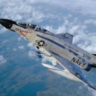
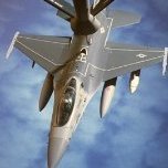
mywifehatesmodels and 2 others reacted to HL-10 for a topic
Hobby Boss's F111-A. This is a development airframe, hence the non standard scheme. Apart for the crew figures, it was built out of the box. Thanks for looking Angelo.3 points -
UNDEAD???!!!!! Everybody beware, Ironwing is a ZOMBIE!!! Ironwing wants to eat your brains!!! Run for your lives. If the women and children are too slow, leave them behind. Aaarrrrggggghhhhhhhhh........3 points
-

Make the others jealous
Rick Griewski and 2 others reacted to ironman1945 for a topic
My wife is very amiable to my crazy model building habit. Always very encouraging. Just had a birthday and she bought me these 2 bad boys. I'm very very lucky! Going to be very busy over the holidays! Gotta finish the P-51B conversion first though! Dave/Ironman19453 points -
$17 for one of these bad boys. Thank you BF sales! It will be built as NL151AM. I want to try replicating the uneven, polished surface and it felt wrong carving up a tamiya P513 points
-

LSP Christmas Raffle 2020
Phartycr0c and 2 others reacted to mark31 for a topic
i will trow in this kit i only donate a item prefer not to enter the raffle Thanks Mark3 points -
Panther V Aufs G 1/16 Trumpeter
dodgem37 and 2 others reacted to josebagasteiz for a topic
Hello everyone. I have started to paint the gearbox and some other parts because I think it will be better that way before putting them in place on the hull. I start by priming with this: The result is this: Then I go on to mark the indentations with black paint: And then I go on to give it its lightened color in some areas: The colors for this step are: Base color Steel Gray by Green Stuff World and FS 37886 by Anmo Mig for lightening With Rot Brown and FS 37886 by Anmo Mig I paint and lighten the brake drum covers.3 points -
3 points
-

Interesting Spitfire IX
Jack and 2 others reacted to alaninaustria for a topic
I just finished building this exact Spit scheme - I do subscribe to the theory that they left the forward upper cowling in camouflage. The reason I believe this is as follows: as a pilot, you would not want a silver or natural metal finish ahead of the windscreen because of the problem of glare/reflection from the Sun’s rays and ambient light. That is why so many aircraft, both civilian and military have a dark color applied to the forward area. Just my thoughts on the matter... Go for it, it’s a great scheme to complete, Cheers Alan3 points -
Valiant Wings Publishing Airframe Album 16: The Messerschmitt Me 410 Hornisse
Royboy and 2 others reacted to alaninaustria for a topic
Man, I wish we had an IM 1/32 scale Me-410!3 points -

As an aside...
mpk and 2 others reacted to Confusionreigns178 for a topic
This is beginning to sound like a Blues track... Maybe by Blind Lemon Bellyache or Slurpin' Joe Itcher..... Chris.3 points -
thanks), just glued, when using high-quality CA and technology, you can't tear it off. Well, considering that the assembled model weighs only 240 grams, that's enough. To be sure, you can add some elements screwed to the end rib on the fuselage parts, which will go into the wing cavity.3 points
-
Some progress I hadn’t recorded - the web supporting the spare wheel (laser cut PLA) & the socket for the davit that raises/lowers the 220kg/485-pound spare wheel assembly. Non-slip on the air sentry hatches added as well. With spare wheel:3 points
-
Sorry if I come across brusque - it's 12.25 am, I'm knackered and about to visit Nod - the cowl has a canvas cover, and it's a different scheme, if I have the time tomorrow will have a look through my reference books.3 points
-

Hasegawa 109F-4 to F-2 conversion..
scvrobeson and 2 others reacted to RBrown for a topic
F through K versions are covered in Messerschmitt Bf 109 F, G, & K Series: an Illustrated Study, by Jochen Prien and Peter Rodeike. The book gives production batches by Werk Numer and documents the various changes during production.3 points -
Thanks Gary I have been involved with the Wings cockpit figures from day one as MDC casts all the figures. We did retail them before we downsized MDC, but I think you should see more of them in the near future as he has some fantastic new releases. Back to topic Wings has a few WW1 seated pilots but has some new ones for the Meng release one with Voss leaning on the cowl of the aircraft and another two figure set with Voss sitting on to of the aircraft accepting a bunch of flowers from a small girl. Bob3 points
-

1:48 Eduard Bf 110E
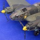
Greg W and 2 others reacted to PeterOlsen for a topic
G'day everyone, here's a bit of progress on the 110 to show you. All the cockpit parts have been cemented into their required places and packed away nicely into the fuselage parts. After all the hard work I always find this to be a bit of a bitter sweet moment on any kit but the build does have to move on. I left out some of the ammunition canisters near the radios which will require a little adjusting to get them to sit in nicely. The two fuselage halves went together rather well and I took extra care to make sure the vertical panel lines matched up on the upper and lower parts of the fuselage spine. This would have been a real mess to correct so its definitely worth taking a little extra care to get things right if you're working on this kit. After clean up they did need a bit of a re-scribe to freshen them up and I also added some rivets with my 1:48 Rosie to replace some of the lost detail. Their is a bit of a gap on the port side of the middle instrument panel ( between the front an rear cockpits ) but this fit very well I just haven't added any cement their yet. Eduard depicts this part as being hollow from the sides .........I wonder if this was the case in real life ? Does anyone have any pics or info on this area ? I was only able to find a front on view of these instruments. ...Below are some pics of the re-scribing and riveting of the fuselage spine. I've added an acrylic wash here so the details pop up better in the photos. And the bottom half...... More in just a tick .................3 points -
And another. Not real sure yet what I'll do with this, perhaps a Tiger turret change, V2 to Miellerwagen, or something else, who knows. Good price though, or I certainly wouldn't have been able to afford it. Really large box and a jillion parts; just too cool.3 points
-
QF-4S Phantom "VX-30" - Tamiya/Cutting Edge, 1/32
Starfighter and 2 others reacted to Rainer Hoffmann for a topic
Once the new set of wheels has arrived and once you've painted them, the old one will reappear from the 11th dimension through a wormhole that spontanously formes on your bench. Mark my words. Rainer3 points


.thumb.jpg.5da8bff9741de420eb2e87addd8f2cf6.jpg)

.thumb.jpg.cd22b958c9e88a898a21e18b862c523e.jpg)