Leaderboard
Popular Content
Showing content with the highest reputation on 07/31/2020 in all areas
-
Thanks guys! I haven't updated in a while because I was busy with other things. Those pics of the Shiden Kai are very nice Matsu! I don't if I'll try to replicate those antifreeze tubes on the prop hubs. I FINALLY received the HGW seatbelts from the Czech Republic so at least that is not holding me up anymore. Less components than a typical Luftwaffe harness system so assembly was relatively simple. Even though the fabric material is much more flexible than brass, it's still difficult to drape these things in a realistic manner. And is it just me but don't all of the seatbelt representations, whether they are fabric or brass, seem a tad OVERscale? Would the lap belts really fill up the bucket of the seat so completely? Anyways... now that the seat is complete, I can take a few more pics of the cockpit. Overscale or not, the seatbelts add a nice finishing touch to the cockpit. Now I have to start getting serious about riveting. I just received another set of Galaxy Tools riveters with the wider spacing. Same vendor as before but instead of having to wait over 60 days, transit time was only 11 days.13 points
-

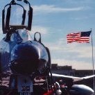
1/32 Hasegawa P-47M Thunderbolt ”Josephine”
Paramedic and 10 others reacted to Tolga ULGUR for a topic
11 points -
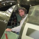
Special Hobby's 1/32nd scale North American X15 A2 Apart from a few scratch built additions in the cockpit, and a pilot figure from Shapeways (3D printed), it is an out of the box build. Various shades of black, dark greys, and metallic tones from various manufactures. Shapeways X-15 pilot. 3D printed. The version I ordered was the "basic quality" one & higher quality versions are available, for an increased cost. This one was rough, but workable. Head/face replaced with a Hornet Heads resin item. He needed some adjustments to get a better fit in the chair & cockpit. Thanks for looking, Angelo10 points
-
1/32 Hasegawa P-47M Thunderbolt ”Josephine”
Paramedic and 7 others reacted to Tolga ULGUR for a topic
This is 1/32 Hasegawa P-47M with the markings of “Josephine / My flying machine” from 62FS 56 FG in Boxted January 1945 Cockpit modified with Aires cockpit set and Yahu instrument panel. Wheels are from Barracudacast I have used Zots decals set (ZTZ32/013) Paints: Gunze Sangyo acrylics and Alclad lacquers. Happy modelling8 points -
I have quit stalling and have begun work on the exhaust stacks. Lots of trepidation, but geez - it's a model; it's supposed to be fun. My plan is to use a combination of .125 inch diameter aluminum tube and also .125 inch diameter solder. If perfectly to scale the diameters would be about .14 inch. But I could not find material that size that would suit this application. I will use the solder where I can because it is easier to bend and form. The aluminum tube will be used for the lower portions of the stacks where they exit the fuselage and the ends are exposed. The stacks must be hollow there, obviously. The aluminum tube must be bent and formed as well - and in order to prevent the walls from collapsing I have filled the ID with .093 plastic rod. Then after forming, I can easily drill away the plastic rod from the ends to regain the hollow. I have a variety of tools and fixtures in which to accomplish the bends and accurately locate the ends common to the cylinder exhaust ports - so far so good I guess. There are three pairs of stacks, each one serving three cylinders. I have started with the middle pair of stacks. What I really need to do this is to mount the engine on the fuselage. But it isn't time to do that yet (far from it), and I don't want to handle the engine a million times in the process (which is what would be required - lots and lots of trial and error here). Also don't you know I would drop the engine on the floor doing untold damage to a 6+ month project. So I made a fixture that simulates the rear portion of the engine and has all 18 exhaust ports accurately located. Here it is with the two almost completed middle stacks: This thing mounts onto the fuselage "bulkhead" that I am using to mount the engine: That bulkhead kind of has a counterpart on the real aircraft, kinda doesn't. The real aircraft has something called a diaphragm that provides an aerodynamic surface for air that enters the cowling and passes out the cowl flaps. All radial engine aircraft have such a thing. But it doesn't support the engine nor is it a firewall - it is merely a thin sheet metal surface. The real aircraft has six flexible "Lord" mounts (motor mounts) that attach the engine to a mount ring. While I will model these "Lord" mounts later, they are too weak and fragile to hang onto that engine, so I had to modify the diaphragm and have it support the engine: I did the same thing on the Thunderbolt. You may also notice the aft fuselage and tail are gone. I have done this on all my 1/18 efforts except the P-38. One, the fuselage is very long and bumps into things. That was painfully apparent while messing around with the exhaust stacks. Two, a staggering amount of work must take place inside the fuselage - cockpit, engine compartment, aft landing gear and empennage. This way all that work can be split up and joining the fuselage halves is easier. I split it at the bulkhead where the pilot seat is hung - along a prominent panel line. Here is the LH middle stack: Inspect it just a moment and you will see it has a long single tube, and two short pieces of solder bonded onto it (with copious amounts of 2-part epoxy and a little putty). Those bends are exceedingly difficult to get just right, and were the reason for my trepidation. Although it fits well to the cylinder exhaust ports, and seems to fit well to the fuselage, I still don't know for sure how it will fit with the upper stacks that kind of lay on top of it. And that is going to be next. Wish me luck - this is the most challenging part of the build to date.7 points
-
First run at the placards left side panel...6 points
-
new pic up now the landing gear Mark6 points
-

A6M2b Zero - Attack on Pearl Harbor - 1/32 Tamiya
chuck540z3 and 5 others reacted to Alex for a topic
Slowly picking out the insane surface detail on the Tamiya zero. They really meant it about *every* fastener. I am going to have to be very careful in laying down a light and uniform color coat to allow this to telegraph through the just the right degree. I'm now wondering if I need to inverse mask the hinomarus (mask so I only paint red and just make sure I get the border with gray perfect). Otherwise they will have two layers of paint and the detail PLW will not be as visible.6 points -

Trumpeter F-100F out
scvrobeson and 4 others reacted to Tony T for a topic
F-100F released... https://www.britmodeller.com/forums/index.php?/topic/235067241-132-north-american-f-100c-f-super-sabre-new-variants-by-trumpeter-f-100f-released/ No sprue shots yet but the specs indicate fewer parts and trees than the F-100D kit. Seem to have ditched the steel legs and likely the engine & trolley parts. Yummy. Waited a very long time for this, Tony5 points -

New Eduard boxing : Bf109E Adlerangriff Limited Edition
scvrobeson and 3 others reacted to Lud13 for a topic
Just saw this at Hobby Search Store..stated its September release but can not find anything on Eduard site. Look like option for Bf 109E-1/3/4 with two sets of wings and canopy's is provided + Galland figure. Anyone knows more detail about this one, would like to grab one for Gallands decals.4 points -
Same here. All the frenzy was like watching a load of girls going mad buying lipstick when they heard Max Factor were discontinuing five colours. I wish Peter Jackson had turned the gifted WnW team to working on Cold War icons. Imagine a WnW Lightning, Sea Vixen and Super Mystère, or those late 'thirties trainers like the Airspeed Oxford. Instead of the Felixstowe, a Boeing Clipper. Alas, we will never know. Tony4 points
-
Filling has begun. At Woodys suggestion, I’m using thinned Perfect Plastic Putty and wiping in on with a tiny spatula. As you can see, it works quite well though I have cleanup to do. The rivets won’t be perfectly smoothed over as the replacement raised rivets and decals will cover them spot on. More to come soon, progress to be made.....and it’s 101F outside, so more time indoors!4 points
-
Hi, Some pics I took from SNASM years ago. Close up of propeller hub, have an antifreeze tube (RED) for each propeller, and some more Regards, Matsu.4 points
-

Wingnut Wings - Large shipment and Meng
Pup7309 and 2 others reacted to Rick Griewski for a topic
naw, no sour grapes here. We are just lamenting with friends online while staring into a glass of cold beer. I have all the WNW kits I want. I am so happy for others to have the kits they want.3 points -
Liberated during quarantine -PB4Y-1
Derek B and 2 others reacted to patricksparks for a topic
The outer wing thinning started with cutting all the ribs out of the upper and lower wing halves, I left the center spar that runs out to the wing tip on the upper wing and removed in on the lower. Using double sided tape I taped the wing halves onto a FLAT board and used a very coarse sanding block to thin the wing starting from where the outboard flap hinge starts and worked out to the tip. I also made a partial saw cut into the leading edge where the wing tip panel line is, I only cut in about a 1/4"(back to this later). I cut out the molded in spar on the upper wing halves about 2 inches from the end of the tip of the wing. In order to get the "twist" on the wing tip so that it is basically horizontal to the top of fuselage you need to sand the rib that the aileron attaches to on the upper wing halves down to zero out at the tips and sand a constant taper back to the outboard flap hinge, you want to remove most of your material from the trailing edges of the upper wing halves in order to get the lower halves to "twist" up to get the tip to become more horizontal. You need to sand the leading edges as well to get the overall outer wing thickness reduced to look better, leaving the wing halves taped down flat , you start sanding from the outer side of the outboard engine nacelles and work out to the tips, you need to sand material from the thickness of the tips as well, this is where the saw cut in the leading edge at the tip panel line comes into play, I carefully "cold" bent the tip leading edge out to be more flat on cross section, sand a constant taper from the nacelle out, you have to do the same on the lower halves but not as much material needs to be remove, you want the upper half of the wing to stay totally flat and the lower half going up hill all the way out to the tips. You have to go back and forth with your wing halves and constantly check them together to make sure they are going the way you want them to. Also the upper wing's molded in spar needs to be tapered along with the leading and trailing edges especially out by the tips so that it allows the wing to thin out in a constant taper. I used thin very high bond solvent to glue the halves together and it give you time to manipulate the tip "twist" while it sets, I also double sided tape a flat piece of wood to the top of the upper wing half in order for it to stay flat while the glue dried(overnight). I did my wings one at a time so that I learned on the first one to make sure it was going the right way and then applied what was learned to the second. Don't be afraid to sand a lot of material off the insides of the wing tips, they are plenty thick and when you flatten them at the saw cut it actually makes them protrude out in front of the leading edge and simply gets sanded back to match. Here are a couple photos of the back edge of the wings, maybe it will help. The sprue that I got the props and engines from are the standard sprues from the HK B-17s all versions3 points -
The antique BoB Revell Spitfire Mk.I
Greg W and 2 others reacted to thierry laurent for a topic
And here's the final ejection system with the ball. I also made the pilot oxygen hose. This is simply made out of a copper wire section with very fine solder rolled over it. Finally I added a small section of Albion tube to reproduce the mask connector.3 points -
To give you an idea of sink marks.....3 points
-
Thanks Nick I didn't want to turn as a Isracast basher. I love the set and enjoying immensely converting the old revell mirage. Renegade, sorry for the Hijack That is solving my dilemna then. Time is not a factor and I will wait for your Italeri Kfir conversion to make a IAF KFIR.3 points
-
Agree on both points on the HGW belts - overscale but still look great. On mine I was initially a bit timid with their instruction to wad the individual pieces of fabric up and mash them around with your fingers before assembly, but it really did help the drape. Next time I will probably assemble with white glue instead of CA to avoid overly stiffening them where there's glue.3 points
-
Yes, thanks. This is the CMK (MPM) H 1/2/3 conversion. A bit more...tinkering going on. Not really serious building just adding bits and pieces where they may be visible. I added some hydraulic lines to the mains and with such a huge greenhouse cockpit I didn't think merely masking and painting the frames would be enough so I took to building some support frames from some .020" strip which will (maybe?) be visible from the outside/ open access panels.3 points
-
I believe the Meng Triplane release has been mentioned previously...3 points
-
Thanks Matt! I sketch a guide line around the spinner and then attack the rivets one quarter at a time. After each quarter run, I reposition the rivet wheel into the previous holes and go from there for another quarter. Next, I decided to rivet the engine cowling. No way to wrap a ruler around that shape so I used the flexible white Tamiya tape to draw my guide lines. The rivets produced by the Galaxy Tools rivet wheel are very fine. Almost too fine. I'm worried about the multiple paint layers eventually filling in the rivets before it is time for the pastel wash. The effect right now is really nice. With the spinner on, the engine detail gets covered almost completely. The spinner attaches via polycap so it will be removable... some consolation.3 points
-
Liberated during quarantine -PB4Y-1
Derek B and 2 others reacted to patricksparks for a topic
Like brahman 104 I spent today working on super chargers, I am fortunate that the HK B-17 sprues that I bought for the props and engines also yielded the exhausts with butterfly valves , flanges and the fairing that goes over the turbine disks. The first photo shows the Hobby Boss turbo charger with the HK B-17 parts above it. the second photo is the HK parts installed onto the Hobby Boss part.3 points -

MESSERSCHMITT BF 109E-7 TROP 1:32, HGW MODELS
LSP_K2 and one other reacted to MH Design Scale Models for a topic
Hey guys, I would like to share a few pictures of my build of Messerschmitt BF 109E-7 TROP 1:32 by HGW Models. If you would like to see pictures of the entire build, please visit my web https://www.mhscalemodels.com2 points -
Thanks guys! The cockpit is basically finished but I can't put it into the fuselage until the riveting is done. I've been procrastinating on this for a while now because the Shiden Kai happens to have a ton of rivets. Now that I've received the New Galaxy rivet tool in the preferred 1.00mm spacing, I had no excuses left to fall back on. The first step is to draw the rivet guide lines onto the model using reference drawings, a flexible ruler and a soft-lead pencil. Because there are so many rivets, the lines started smearing. I decided to hold off on the more tightly spaced "intermediate" rivet lines and get the main grid lines in first. Once the lines are drawn, I simply roll the rivet tool over the lines. A decent amount of pressure is needed to make holes in the plastic and my rear fuselage joints buckled in a few places. After riveting, I removed the pencil lines with Windex. At this point, I was thinking about leaving the intermediate rivet lines off. I mean, who is really going to notice? Of course, I was compelled to complete the job and I put the intermediate rivets on as well. At this point, the rivets are like little pimples... each hole is surrounded by a mound of raised plastic. I don't like how this looks so I try to sand off the mounds and leave only the holes. It's another step in the process but I think the results is worth the effort.2 points
-
Wingnut Wings - Large shipment and Meng
esarmstrong and one other reacted to Archimedes for a topic
I don't understand where you are getting sour grapes from. I don't see that in this thread at least.2 points -
All those letters for weapons frighten me. That's why a vast majority of my dioramas are armor or WWII aircraft. Us Army guys can't understand what AIM or the others stand for. All we understand is "Guns go boom"2 points
-

1/32 Hasegawa N1K2-J Shiden Kai 343-45
chuck540z3 and one other reacted to Thunnus for a topic
I do the crumple thing on all of my HGW belts. I actually did the reverse process as you... initially I crumpled them too aggressively and that led to the painted finish cracking and peeling off so now I do it a little more gently! I use a PVA glue but I still lose flexibility at the glue joints. Oh wow... thank you Chuck! I greatly appreciate your comments and really respect your opinion as someone who represents, to me, the level of modeling/presentation that I want to reach. I'm not a good modeler yet but the journey from mediocre to ok has been helped tremendously by posting my builds here and learning from all of the great builders that frequent these boards. I've gained a ton of knowledge just by reading other people's builds and I've wanted to record my work in a way that would be similarly helpful to others. Plus, I like photography so that helps too! Yeah, the placement of seatbelts is very interesting. The fact that we have aftermarket belts available is pretty cool but I agree that bunching all of it onto the seat is probably not realistic. Folding and bending is one way of making the harnesses look more natural but extending the drape beyond the seat itself and/or introducing twists may be the next step.2 points -
For color schemes: yes, all USAF F-15C/Ds in Desert Storm were still painted in the 1970s-era "Compass Ghost" (lighter) 2-tone gray scheme; specifically, FS36375 and FS36320. I don't think the "Mod-Eagle," or "PACAF-Eagle," darker 2-tone gray scheme started to appear until ~1992, a year or more after Desert Storm. The Eglin jets had a mix of "original" color national insignia and the newer, tactical black outline national insignia. Recall the color U.S. insignia were the "borderless" full-color blue disc/white star/red white bars, without the overall blue outline surround, as applied by McDonnell in the factory-paint scheme, and maintained by USAF paint shops until they began the black-outline insignia. Check photo references for the specific airframe you want to do. I recall some of the full-color aircraft had their 2-tone gray camouflage so faded that it nearly looked like one color overall; which would make an interesting model. As to "MSIP" upgrade: also yes, all the C-models in Desert Shield/Storm had the MSIP upgrades and would have had the cockpit layouts and antennas associated with that. The Eglin jets, specifically, were 85 and 86 models, and were MSIP configured from the factory...but that is completely separate from the camouflage/color schemes at the time...so "Light Grays" and MSIP configuration for all the Eglin, Langley, Bitburg, and Soesterberg F-15C/Ds in Shield/Storm...also: AMRAAM AIM-120 missiles did not get to the theater until the end of hostilities with Iraq...F-15 CAPs in April 91, and maybe as early as March, began carrying AIM-120s, but during air-to-air engagements of "Desert Storm" proper (Jan-Feb-early March), ordnance loads were AIM-7Ms and AIM-9Ms...hope that helps. Cheers.2 points
-
Need to get these 2, my credit card just ran away, gotta go find it.2 points
-
The antique BoB Revell Spitfire Mk.I
Greg W and one other reacted to thierry laurent for a topic
The problem is solved thanks to the water filter contents! I just have to add a small thin wire to the ball and glue it behind the Barracuda part.2 points -

1/32 Hasegawa N1K2-J Shiden Kai 343-45
Kagemusha and one other reacted to chuck540z3 for a topic
VERY sweet looking cockpit John! If I might offer an opinion, I have noticed a distinct improvement in your modeling skills over the past 3 years, from very good to currently simply awesome. I now look to your work for inspiration, so thank you for pushing me to improve as well. You have become without a doubt one of the top modelers in these forums, IMHO, and that is saying a lot with the company we have here. Your photography has improved a lot as well, which is a big part of what this WIP forum is all about. Cheers, Chuck2 points -
That's because I mastered the Fisher cockpit and includes my seats.2 points
-

Wingnut Wings - Large shipment and Meng
nmayhew and one other reacted to Dave Williams for a topic
Not at all. If someone wants to pay that much, that’s their choice.2 points -
Liberated during quarantine -PB4Y-1
Derek B and one other reacted to patricksparks for a topic
Started doing a little work again, had to "Time Out" for a little bit, I was hitting the wall modeling wise... Anyway I did some re-scribing on the engine nacelles, not quite done yet. I finished putting in the "Tunnel Gun" windows. I started to re-work the lower nose, the conversion to a PB4Y-1 with the ERCO nose turret requires a different profile on the lower nose, this only applies to the early conversions of "D" model air frames, the first PB4Y-1s were standard B-24 Ds and then they started to convert some of them with the ERCO turret, later production aircraft had the nose more the shape of the "J"s lower nose shape. Of coarse I chose to make the earlier. The first photo is the kit's nose being cut off and the clear bomb sight window is in place to show the shape difference, the second photo is a forming(black styrene) that I made to replace the original lower nose. The earlier nose didn't have the clear sides on the bomb sight window, only some small rectangle windows that I have to add, other versions had no side windows at all. You have to do some research when building one of these!!!2 points -

1/32 Trumpeter F-14A Tomcat
vvwse4 and one other reacted to Mark Jackson for a topic
HOLD THE PRESS! I had a nagging doubt, something was not right and I knew that I could obtain a better fit. So even though the two panels which seal the wing box area were super glued in place, I used a metal rule to snap them off. It could have ended in broken mess but the modelling gods must have been looking down and both panels had no plastic breaks or tears. I wanted to obtain an accurate wing sweep, droop and minimize the gaps around the wing where it sits inside the wing box. All too often you see great looking Tomcat models but they have big gaps where the wing sweeps in and out. The Trumpeter rubber wing seal bags are not easy to work with and require some scalpel slicing to create the correct level under each wing. The wings move independently but the mechanism is hit and miss so both wings will be fixed. Then the gaps will be filled and made good.2 points -

1/32 Hasegawa N1K2-J Shiden Kai 343-45
Martinnfb and one other reacted to spyrosjzmichos for a topic
Excellent work! One day I have to man up and try my hand at full riveting!2 points -

HK B-17...C 5/4 sweating the metal
Greg W and one other reacted to brahman104 for a topic
Thanks Peter! Yep, I'm pretty happy with how they've turned out. Always learning though! Thanks mate. It's all relative though.... my skills have grown exponentially through this project alone, but it might be another 44 years before I finish it! Wow! another month flashes by with the blink of an eye. Precious little time spare for the bench, but...... Since I've moved to NZ and completed conversion onto their platform of choice I've been kept very busy. I thought I'd share a few pics from last week of the new bus. In my mind, still not as awesome as a Chinook (I am possibly biased), but not altogether bad either . Especially not when I get to fly around places like this! Yes, all three are of me, freezing my a*$e off in -10 degrees at 7,000 feet. I know for some of you that's nothing, but when you've lived pretty much all of your life in the tropics........ Good fun though! Back to the build. I've been chipping away for what seems like forever to blend the kit and my printed nacelles together in preparation for casting. I don't know how Iain is doing it with his Andover build, but I've certainly had enough of sanding for a while! So this is where they're at now: They still look a bit rough, but they are in fact quite smooth. It was quite challenging to recreate the seam that runs around the nacelle. As always, it's done 90% by eye so hopefully will look the part once it's all together on the wing. The shape of them alone makes for a challenging proposition when casting. No I'm certainly no expert on the matter, but hopefully by each nacelle on these brass pins, everything should stay in the same place. Because I could, I drew up and laser cut some MDF for the mould boxes. I figured that would support the weight of the pin a bit better than simple balsa wood. So that's pretty much where it's at right now. I'm waiting for the first pour of the silicone to go off so I can pour the second half. I really hope this works, as I don't fancy going through this process again! Cheers, Craig2 points -
Hi folks, hope you're all keeping well. The wing tips required quite a lot of work to prep for lighting. Lots of thinning required to allow the electrics to fit and some careful carving of the lit areas that will be visible. You can also see the wingtip nav light in the prep stage as discussed previously. The good thing about EL panels are they are quite thin but you need to be quite conservative with how much you use as a 3v coin battery doesn't drive a large amount of it (typically <25cm for good brightness). I had to use two strips back to back so that the top and bottom illuminated but wasn't sure what it would look like side on or whether it would just short out! That arrangement made for quite a bulky wiring connection but luckily the Revell plastic is quite thick so can take a fair bit of hacking. Before assembly I sprayed the wing insides black as the thinness in some areas would easily let light bleed through and make it look like a ghost ship! Once trimmed to the right size, I added thin clear plasticard on top of the EL tape so that I could scribe in some of the distinctive panel lines you see on the wingtip slime lights. I scribed a single longer sheet of plasticard with the same lines so that even if they weren't quite perfect they would all line up when I cut each of the 4 sections (2 wings, top & bottom) out. I wasn't sure how to make sure the wingtip slime lights blended together (rather than look like 4 layers sandwiched together) so I used CA glue to help create the final shape and seal the EL tape (hoping it wouldn't short the ends again!). I'll need to lightly coat the lights with the right colour to stop them looking so green. On this photo you can also (just) see the fuel dump amendment I made by adding a squashed bit of copper tube and the modified ECM bullet which looked too small so I removed the original, added a longer bit of sprue and shaped accordingly. And of course the fingers crossed moment..... And breath. Next, it looks like I need to return to the forward fuselage area for some more rivet love.2 points
-
Awesome! Looks really great2 points
-
Most impressive Cheers Dennis2 points
-
Nice effect. Sincerely, Mark2 points
-
Impressive work as always, John! Kev2 points
-

1/32 Hasegawa N1K2-J Shiden Kai 343-45
Martinnfb and one other reacted to Dpgsbody55 for a topic
Looking great. Even though the spinner hides a lot of your work, it still looks impressive. Like your riveting, too, but I'll refrain from making the obvious comment on that. Cheers, Michael2 points -
Liberated during quarantine -PB4Y-1
TAG and one other reacted to patricksparks for a topic
Wanted to make the sea-search radar dome that replaces the ball turret on PB4Y-1s, I had to find a way to make it with no lathe, I had no dowels no urethane foam board, all at work, there I have an industrial shop with everything.... But I did make sure I bought a $99 dolllar vacuum form machine off Ebay a couple months ago when the CO-19 hit. I searched around the house this morning and to my surprise I came across the ice cream scoop, it has a cap on the handle that is the perfect size for the radome, I popped it off sucked a shot over it,put the cap back on and threw back into the drawer !!! I had to fill in the hole for the ball turret and it's barrels as the turret is a bigger diameter than the radome, I am happy with the results so far, I also made up a faux plywood deck to cover the ball turret opening in the cabin and added a contrived mast and bracing for the radar installation.2 points -
Liberated during quarantine -PB4Y-1
Derek B and one other reacted to patricksparks for a topic
Printed my bomb bay fuel tanks and painted them today, added some foil tape for straps and a couple decals for interest. I had to make these tanks up, I couldn't find any reference photos or drawings of the tanks the B-24/PB4Ys carry, the only thing i found was written reference that said that there were 2 tanks carried in the forward bomb bay and I beleive it said that they were 350 gallons each, mine are probably a little large but I'm happy with the way they look...2 points -
Liberated during quarantine -PB4Y-1
TAG and one other reacted to patricksparks for a topic
Got around to finishing the pilot's seats added some Eduard B-17 belts. I decided to put the seats in 2 different positions as the kit comes with both seats all the way back to the bulkhead, I simply put a piece of styrene strip in the back notch of the left hand seat rails and knifed in a new pair of notches on the front portion of the rails, just thought it would look a little interesting.... Also started putting the Eduard engine set parts into the back end of the engine nacelles, I was going to glue them into the nacelles but I realized it was easier to glue them onto the wings, they line up right on one of the kit panel lines, left to right is simply putting the kit nacelle in place and marking the location with a pencil...2 points -
MiG-29A in Luftwaffe Service
blackbetty and one other reacted to Madmax for a topic
Thanks dashotgun. Amazing what a powerful self-critique tool posting photographs on a forum can be. Looking at the last photo I posted, I realised that the panel lines were totally uniform and overstated. Some panels get removed often as I mentioned, but others don't, and shouldn't have the same treatment. I decided to use a grey wash some on of the panels to soften the overall look, and here you can compare the top of the photo to the bottom (left side) to see what I mean. Accentuated panel lines are a contentious issue as it is, and I think some variation helps. Apart from that , and some work on the radome to get rid of the black primer that came trough on my slightly heavy handed chipping scrub, the model is finally done. Here is a little foretaste of how she looks... Many thanks to all who have shared this little journey - it has been good fun! Detail photographs to follow on RFI tomorrow... Sean2 points -
Conducted a few tests today. First was figuring out if the Mr Hobby lacquer colors that I purchased for the Shiden Kai would allow hairspray chipping. On my paint mule, I sprayed a base coat of Tamiya AS-12 Silver. Over the tail, put on a layer of MIG Scratches Effects liquid and forward of that I sprayed MIG Heavy Chipping Effects. Once those dried, I sprayed the tail with the Mr Hobby Kawanishi Cockpit color and then the Mr Hobby Kawanishi Dark Green forward of that. Just to compare the different greens that I had on hand, I also sprayed Mr Hobby Aqueous H-59 IJN Gloss Green and Tamiya XF-11 IJN Green. Using a stiff paint brush dipped in water, I was able to created chips on the Mr Hobby lacquer colors fairly easily. But I didn't quite like the way the Mr Hobby Dark Green sprayed. For one, it was dead flat, which I'd prefer not to deal with over the whole aircraft. Someone also question the accuracy of this particular color. I'm no expert and doing some internet research and finding some articles on Shiden Kai colors by Nick Millman didn't clarify matters conclusively. So... I'm decided on which green I'll be using to paint the exterior of the aircraft. But at least I can move forward on the painting of the cockpit. I conducted another test with the Galaxy Tools riveter. Compared it with the RB Productions Rivet-R and Rivet-R Mini, all of the tools set at 0.75mm spacing. Ignoring the crookedness of the lines, all of the rivets looked about the same, which is a good thing. From top to bottom are: Galaxy Standard, Galaxy Mini, Rivet-R and Rivet-R Mini. I also confirmed that the Galaxy Standard and Mini wheels in the 0.75 spacing are exact matches. I can re-trace the rivet line I made with the Galaxy Mini with the Galaxy Standard and riveter will put the points exactly in the rivet holes along the entire length of the line. The Rivet-R and Rivet-R Mini aren't exact matches. By carefully placing a point on the Rivet-R wheel into the hole made by the Rivet-R Mini and running it along the rivet line, you are making new holes by the time you get to the halfway point. Seems like a minor point but having exact matches eliminates at least one of the headaches I've been experiencing when riveting.1 point
-
The model shows FLEURIE – a Char B1bis of 41eBCC (Bataillons de Chars de Combat) to its way to Stonne, just stopped here with mechanical breakdown caused by a broken steering link. The crew desperately tried to become FLEURIE clear again and into combat condition but had to gave up their tank. Tank model Tamiya, figures uhhm…forgot the mix of brands I have used here.1 point