Leaderboard

Popular Content
Showing content with the highest reputation on 07/05/2020 in all areas
-

Tamiya 1/32 JASDF F-4EJ Black Panthers
Greg W and 11 others reacted to spyrosjzmichos for a topic
Hello everyone! First off, a very big thank you to Ben Schumacher aka Starfighter for designing and 3D printing the tail fin sensors and to Colin Robinson aka crobinsonh for providing the extremely rare Zotz decals F-4EJ resin conversion parts. It's people like you that make me appreciate this hobby even more! I used a razor saw to cut off the kit's plastic sections and superglued the conversion parts in place. The tail fin sensors required a bit of blending and for this I used Milliput epoxy. It has been mentioned several times before but I've also had similar issues with the transparencies. Because of the way Tamiya has moulded the sprue gates, the clear canopies end up having fracture marks on one side. I filled in those sections with superglue and sanded everything smooth till clarity was restored. The marks that have remained will be covered with thin strips of masking paper to simulate the canopy insulation strips. I also added more detail on the weapons pylons in the form of rivets and wiring. This concludes the construction stage and I can finally move on to painting! A few more pics of the main airframe and subassemblies.12 points -
Happy 4th of July everyone! We are just going to hunker down and have a quiet celebration at home... seems fitting with what's going on at the moment and gives me some more modeling time. Here is the Type 98 gun sight with all of the bits added on and painted.11 points
-
Since I’m reaching the end of my vacuform build of one, it’s clearly an English Electric Lightning!10 points
-
Significant progress today. There are still a few small things to complete here, like the bungee on the seat height mechanism and some gas cylinder plumbing, but it's moving right along now. The shots below are just dry-fit (which of course fits perfectly and hangs together because Tamiya). I can't install the seat until my HGW seat belts get here. I may shift gears after this and start prepping parts and base coating the engine. I really need to study both Sean's excellent build and my Aero Detail book (when is it getting here!?) with regard to the back of the engine, plumbing, wiring, etc between engine and firewall. I'm determined to make that whole region visible with removable panels and cowling, so I've got to build a credible mess o' wires and linkages.10 points
-
Yes, yes, I know that there is Tamiya's one the best. But this old model had been put onto the bench when I and my friends decided to organize local group build with the slogan: "Building kits older then their owners")) So, I blew a dust from the box and started. I decided not to dive into extensive and expensive way of total correction and make it for fun BUT... I've already had Verlinden cockpit and two old Eduard sets need to be deployed. Just one thing bothered me yet - an ENGINE. If overall exterior is simple but pretty decent, the engine is just ugly. I had pair of Quickboost R-2800 but they didn't fit big Revell cowling, just hanging out inside and moreover didn't resemble particular engine model in details. Finally I decided to make my own "quickboost" using 3D and futher aim to adapt it to different models uncluding other scales, for example 1/48 Corsair and bunch of old Monogram bombers and, of coouurrse 1/24 P-47D)) As for this Corsair plan, it will be one of VF-17 (likely "Chico" Freeman plane) in flight configuration (not to build undercarriage). So, the progress in the pictures below. Engine itself consist of three large parts (crankcase, first and second rows) and three small (magneto, airscrew governor and oil pump). Backplate is separate part just for Revell Corsair to adapt engine to the model.9 points
-
Here I present my Roden Fokker Dr.1 (before Meng gets theirs out). This is Josef Jacobs' ride, complete with a Clerget 9B engine (captured from Copper State Models), extra braces on the landing gear, God of the North Wind graphic taken from an enhanced photo of Jacobs' plane, and the cowling is made from aluminum I spun on my lathe. Jacobs' plane was a glossy black, as well. There is a build log on ww1 aircraftmodels.com. Thanks for looking and comments are welcome.9 points
-

New HKM 1/32 model coming soon...
Out2gtcha and 8 others reacted to Alburymodeler for a topic
I will be waiting outside your house for the postie to arrive. i might even get it while you are at work.9 points -

HB B-24D
scvrobeson and 6 others reacted to leoasman for a topic
I've started painting the tails using more masks from the Silhouette. (I love this thing) The markings seem high on the tail, but I've included a photo showing them on Teggie Ann. I opted to put them a little lower for ease of alignment and artistic license (wink wink) Also, I didn't realize that the little flag marking was also on the inside of the tail until I saw this other photo. Anyone have any idea why that is?7 points -
I know more about what the kit isn't, than what it actually is, and I don't think anybody has guessed it so far yet. All I know about it is that it's a new kit that has not been previously announced or discussed. It's been ready for over a month, but distributors asked Neil to hold off on the release due to COVID. In any case, whatever it is, Neil's sending me one on Monday, so I guess I'll know at least some time next week. And if I'm allowed to, I'll share it with you guys (I may not be, however). Kev7 points
-
1/48th Boeing B-52H Stratofortress
Greg W and 5 others reacted to tomprobert for a topic
Evening all The B-52 has external hardpoints between the inboard engines and the fuselage - modern day H-models can carry a wide range of weapons on these pylons from the basic 'dumb' free-fall bombs to the most modern and sophisticated cruise missiles. As the Sanger kit comes, there are no external pylons provided but their locations are marked on the wing. However, these bare no resemblance whatsoever to the large pylon mounts seen on the real aircraft: IMG_0308 by Thomas Probert, on Flickr B-52H Underside by Thomas Probert, on Flickr As my model will be finished without the pylons, I needed to make a more accurate representation of the mounts, so I grabbed some plastic card from the stash and started to fashion them: IMG_0312 by Thomas Probert, on Flickr IMG_0313 by Thomas Probert, on Flickr Lots of careful trimming and sanding ensured a nice, snug fit to the wing: IMG_0319 by Thomas Probert, on Flickr I presume on the real thing the pylons are mounted to this plates - and I use the word plates as that just what they look like and have very little in the way of surface details. Both are now done and look like a significant improvement over the original kit offerings and are certainly more in keeping with the real aircraft: IMG_0317 by Thomas Probert, on Flickr IMG_0318 by Thomas Probert, on Flickr That's another job done! Take care all, Tom6 points -

New HKM 1/32 model coming soon...
Daniel Leduc and 4 others reacted to MikeMaben for a topic
You can tell just us Kevin, we all promise not to tell Neil , he'll never know.5 points -
I bet its a Fokker Dr.I hehe....5 points
-

EE Lightning - Echelon vacuform
Daniel Leduc and 3 others reacted to mozart for a topic
The remaining scoops and protuberances have been fitted. I need to sort out the area below the coaming in the cockpit which had a little butchery applied earlier in the build, then I think a coat of primer might be in order!4 points -
I was working on the main gear doors. As is well reported the lower edge should be straight, not curved. One straightened and compared to unmodified kit part. I'm not too content with the results as now the door is too narrow at the front end. No one would notice right? Since I had a lot of fun making a gun bay door cover for the Me 262 I decided to try and make new gear doors from scratch. More work, but who cares. I cut out two new doors from an empty beer can, production of which has been exceptionally good lately. The things I do for modelling... This basic shape will be laminated with very thin stock card, and then I will cut the inner details with the Silhouette from the same stock and dress them inner surface up a bit. We'll see... This is where the little Spatz is at now. All primed and lower surfaces have been painted MRP RLM 76. The wings are still loosely attached as I want to spray the cammo pattern under the wing roots first and this area is much more accassible this way. The wingroot-to-fuselage fit is again excellent! More than that. Design of the parts is such that glueing them in place enforces them to assume the correct anhedral.4 points
-
What's so funny and confusing about Boeing 307 Stratoliner? A beautiful machine: With some nice options for markings: And there's even a choice for those with limited space: Juraj Juraj4 points
-
And it's 9 months already since the first idea. Just enough time for a new model to be born... So here we go. This is the prototype of the fuselage section I've made for Jan, so he can adjust his house for building the model: And here's the render of the part which reveals the type for those still in doubt: So, HKM, what do you say? Juraj4 points
-
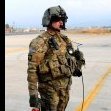
1/35 KH MH-60L "Super 63"
Greg W and 3 others reacted to Hawkwrench for a topic
I painted the C2 console tamiya rubber black followed by a tamiya black wash and finally some dry brushing using tamiya Sky Grey and added some electrical connectors from evergreen rod and painted them Vallejo dark exhaust. I finished up the console wiring and now starting the minigun wiring using detail master DM-1420 hose. (Works perfect for wiring). Boy, these are a pain to get glued in!!! That's all for now. Tim4 points -

New HKM 1/32 model coming soon...
petrov27 and 3 others reacted to Darren Howie for a topic
I still think Hasegawa found the right balance in 32nd and 48th with their kits. You could build em out if box or go ballistic and both routes got you satisfaction.4 points -
Remember last year Neil sent out feelers regarding what scale modellers would prefer to see a Sunderland in??4 points
-

SH Tempest Mk V "Kicked Up A Notch". January 14/21 New eBook!
Sakai and 2 others reacted to chuck540z3 for a topic
Thanks Guys! I have closed and finished off the front fuselage halves, using my usual technique of using Tamiya Panel Line Accent Color in Black to check for flaws. After sanding, every panel line was re-scribed and just about every rivet was re-punched, so there's a high chance of slip-ups that could be revealed after the first coat of paint. By adding a dark wash now, these flaws can be seen and fixed easily, so I now hardly ever have to fix something after painting which can be a real pain. After sealing up the front fuselage, I found plenty of little slip-ups here and there and for the most part, they are all fixed now. I notice quite a few other modelers using this method recently, so maybe I started something? The dark wash would ooze into tiny cracks that would otherwise be invisible to the naked eye. There were a few, which I have now fixed. Note there are no gaps around the rear landing gear well, due to the modifications I did above. This kit has lots of fine rivet and panel line detail, but not all of it is very clear. Re-doing much of it brings it back to life. In a month or two, it should look a bit like my last model of the Kitty Hawk Harvard below, which had a very smooth and glossy yellow finish. With a big investment in early flaw detection, it paid dividends later with yellow paint that was hard to touch-up. With a weathered camo-finish, this model should be even easier to eliminate surface flaws. I'll be gone again for a few weeks, so no more modeling until I return. Thanks for checking in. Cheers, Chuck3 points -
Here is my latest scratchbuild, a Thomas Morse S4C, known as the Tommy. I think this is a significant plane as most WW1 aviators had time in one. This 1/32 scale rendering has a Vector resin engine and a turned aluminum cowling. Turnbuckles by Gaspatch and Eduard. Insignias painted on. Thanks for looking in. Comments welcome.3 points
-
The build is complete. All in all it was an enjoyable build and the final result was decent. I did not add very much scratchbuilding; a couple of O2 lines in the pit, the canvas cover in one of the wheel wells, and some minor stuff on the aerial. The camo turned out well, especially the mottling that has a nice toned down look to it. The weathering, while not perfect, is viewable. The figures turned out very well and I think they are perfect for telling the story of a pilot prepping for a mission. I took some quick photos with a basic photography setup on my bench. I will get the photo tent, lights, etc setup tonight and shot some better photos to include a few "scene setting" type shots. I will be starting the Mark I Hurricane tomorrow and plan to make it the ying to this build's yang - i.e. I plan to show it returning from a sortie. Ernest A few shots of the base under construction, such as it is. Airfield scenes are about as easy as it gets when it comes to diorama bases. I added a bit of bushy grass and some natural ground debris; the purpose being to suggest a tree line just off the base. Ugh, white balance is a bit off on this one. More to follow!3 points
-

Lukgraph RWD-14b Czapla announced
scvrobeson and 2 others reacted to Trak-Tor for a topic
https://translate.google.sk/?hl=sk&tab=rT#view=home&op=translate&sl=pl&tl=en&text=Czapla Something like "Tchapla". Means Heron, in polish. Juraj3 points -
I'm tempted... But I'd need Jan's agreement on it, as it's essentially his idea and project. And still I'd bet my best shoes that it's not the one HKM have worked on. They are not that crazy! Juraj3 points
-

New HKM 1/32 model coming soon...
Rick Griewski and 2 others reacted to Jan_G for a topic
that's my bet as well we will get nice simple B-29 just front section interior, bomb bay, engines, undercarriage, no more details needed looking forward jan3 points -
Thanks Marcel. We moved recently, and what a mission. Internet not working properly yet, so I'm trying an app on my phone. Hope the images are visible... Got some work done on the Cheetah E nose, and sprayed a coat of primer on it.3 points
-

Silhouette Cameo Stencils
Sepp and 2 others reacted to Wrongway_joe for a topic
I bought a Cameo 3 at Hobby Lobby last year, just before the Cameo 4 was released, and have been playing around with using it to create different types of masks. I have several Bandai Star Wars TIE Fighters and wanted something that would be easy to mask the solar panels (24 for each kit!) The Studio software tools are similar to Coreldraw and you can create complex shapes using Bezier curves. You can import a picture and draw over that to create a shape, like a mask for a national insignia, serial numbers, or a pilot's personal markings. You can use a variety of masking materials (Silhouette, Cricut, Friskit, etc.) and Silhouette and Cricut sell transfer tape that is available at Hobby Lobby. I picked up a vinyl stencil product, Oramask 810, from Proworld that is used by some of the aftermarket mask makers. It is translucent so you can see where you placing the mask on the model. It comes in 12 inch wide rolls and you purchase it by the yard. The Proworld pricing for quantity purchase makes it cheaper to buy ten yards than five yards. The Silhouette website has quite a few tutorials and manuals and a link to their a YouTube channel with many videos on how to use the Cameo. I also found a railroad modeling website RMWeb.co.uk that has a forum thread on using the Silhouette cutter, including how to cut or score thin sheet plastic to make buildings or train cars. The thread started in 2013 and runs to 98 pages so it takes a while to work through it but it has a lot of tips on using the Silhouette Studio software. Hope this helps.3 points -

New HKM 1/32 model coming soon...
Rick Griewski and 2 others reacted to LSP_Kevin for a topic
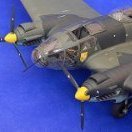
I honestly don't know what it is, or whether any of what I'm surmising is actually true. Time will tell! But my hope is that it's either a Bf 110G-4, or a He 177. If it's anything other than those two, then I'll probably be happy anyway. Kev3 points -
The only other hint I've been given is that this kit will be somewhat simplified, more in keeping with the Meteor than the Lancaster. Kev3 points
-
New HKM 1/32 model coming soon...
Rick Griewski and 2 others reacted to Pup7309 for a topic
WNW’s Handley Page3 points -
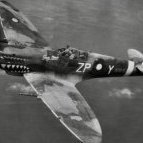
A Battle of Britain Hurricane!3 points
-
No it's going to be a Hampden: that's probably the HK people on the left checking things out. Or maybe not Jari3 points
-
What really fits is a Petlyakov Pe-8! 4-engined, and a lot harder on the nit-pickers!3 points
-
It's almost been half a year and I finally pulled the Spit back from the SoD. The cockpit recieved its dark green wash and a flat coat. The IP is finally finished with the instrument glasses made from clear acetate. How could I evere live without a punch and die? Stay tuned for more progress on the camera assembly. I decided to scratch the camera cradle and leave the camera compartment wide open. Cheers Joachim3 points
-

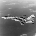
[W] F-16C/CJ Block 50 - Tamiya 1:32
HerculesPA_2 and one other reacted to Gelerth for a topic
I fit the wheel bays somehow but it leaves a small gap: I used the kits screws and a fair amount of CA glue: Rear view: . Now to front bay. Kit vs aftermarket: I've painted it as later it will be difficult to access all areas: Prepared to glue: Fitted quite well, but... I had some problems with closing fuselage halves - resin was too high, had to cut some: And already with front part of intake and a lot of putty: Comparison with CMK intake which is one big part. Nice fuselage details but wheel well is not too detailed: . . . 've been working on gun and gun bay: . .2 points -
Riku, From my limited knowledge, the e wing had the 20 mm cannon outboard of the 12.7 mm MG. Sprue LL in the XVIe kit has the appropriate wing cover panels. I believe the upper and lower wings are the same in both kits. Some of the IXe models would have had the Packard produced Merlin 266 with differences in superchargers and intercoolers-not a big deal if you leave the engine panels on. Those sprues are E and H in the XVIe kit. v/r Rob2 points
-
The antique BoB Revell Spitfire Mk.I
RLWP and one other reacted to thierry laurent for a topic
Don't worry! I appreciate constructive comments. The Spitfire Mk.I pictures I have checked showed a strengthening bar located more or less in the middle of the radiator faces. So, even if the internal components are different from the late marks ones, you still see 'two' meshes (even if it is very probably a single one with a strengthener put in front of it). Accordingly, with the scale effect, I considered recycling the Mk. IX parts to be acceptable to get something that 'looks' reasonably ok. Replicating perfectly the faces would have been far more difficult as this would have asked for cutting fully new meshes and rebuilding the frames with thin plastic strips that would have been too thick. As I wrote it is better but not perfect because I had to accept compromises. To me, the only good option would ask for designing ad hoc photoetched radiator faces. Alas, as I wrote nobody did it and doing this myself was far over the amount of effort I was ready to invest for that kit. I hope this explains that.2 points -
Jan, you know it's going to be Boeing. The civilian one. We have discussed that a few months ago. And they could use some parts they have made already too. Maybe I should post some renders... Juraj2 points
-
exactly Kent I know, one can dream2 points
-
Something like this? (Rendering by Piotr Forkasiewicz)2 points
-
The antique BoB Revell Spitfire Mk.I
Starfighter and one other reacted to thierry laurent for a topic
Now, we will have a look at the radiator main structure. Finally, I could use part of the original radiator plastic part. It was too shallow but as the radiator itself was not correctly positionned, I could at least retrieve the front ramp section. I built the radiator itself and the rear ramp out of leftover bits of 1mm plastic card. I simply copied the too shallow front faces and the rear ramp and extended them. I used sections of leftover RB Mk.IX and Eduard Mk.II radiators to make the faces. Normally, both meshes should be located in the same axis (whereas the Eduard part is slightly protruding). However, when the radiator is located in the wing, this is not noticeable. I already had to cut and sand the photoetched mesh parts and this is not really easy without damaging them. Alas, I could not use any existing photoetched mesh as such as the Mk.IX radiator faces are different, the Tamiya kit has a slightly larger cross-section and the Eduard parts stupidly copied the too shallow radiator faces of the recent Revell Spitfires Mk.II & IX! By the way, I hate when so-called detailing parts are just adding a layer of "detail" on inaccurate parts rather than taking the opportunity to correct them! One challenge was the fact the ramps must be bent to mate correctly the wing. Just take your time and dry fit ten times to get the correct stance. This shows the new radiator part in the wing: Here is the front face: And the rear one: Not perfect but far better I think. Sorry for the quality of the pictures but the section to capture is very small to focus correctly and you need eigth arms to handle the kit and the camera! Now I still have to add the final external details on both sides. Another problem out of the list...!2 points -
TBH .... I've always thought that's his best bet - let the cottage industry go to town on the super detailing. Mind you - easier said than done isn't it?? ... To include just enough detail for Joe Average - without causing cost blow outs for over tooling. Rog2 points
-

Italeri TF-104G Marineflieger - final struggle
themongoose and one other reacted to Fanes for a topic
A lot of progress but not much is worth taking a photo - except you want to see me filling and sanding seams.. Just the nice bits for today. The elctronic bay is glued into place and has recieved a wash + flat cloat During installing I managed to break of the ejection seat handles, so I will reinstall them with the final bits after painting. To get the fuselage ready I have to install the engine (completely invisible) and the nozzle. After playing with my Alclads (and Radu's brilliant spatter stencil) the brassin nozzle looked like this: Scrolling through pictures of the MTU engine I noticed that the nozzle was quite blotchy and everythin but uniformly coloured. Additionaly the recessed parts were of a lighter shade. I'm quite happy with the outcome. After a quick wash with dark brown (almost black) oil colour: And a closeup of the left part. The cone behind the flamholder shows a brownhish wheatering in most pictures so I added some burnt sienna oils. That's it for now - I'll head back to the bench to some more sanding. Unfortunately the new pylons from videoaviation arrived today while I wasn't at home. Two more days of patience2 points -
Ok, so were doing this again? World War II aircraft (technically the Gloster Meteor is WWII too) This would rule out the F4 Phantom + I seem to remember the P-51B being dropped after ZM announced they are working on it? Please no more bombers... My two cents goes on the Junkers Ju 52 (nicknamed Tante Ju ("Aunt Ju") and Iron Annie) And if this would be the case, I for one would be very happy! Kent2 points
-
Just get on and announce it for God’s sake. all this announcing an announcement is bs2 points
-
Thank you Robert and Michael! With the majority of the PE pieces assembled, if not permanently glued in or painted yet, I thought it would be a good time to dry fit the cockpit assembly. Many pieces are just sitting there so there is probably alot of misaligned and skewed parts. But it gives a sense of the scope of enhancements that the Brengun PE set brings to the table. There is still lots to do in the cockpit including the photoetch and acetate instrument panel, seat harnesses, maybe some wiring and painting, of course. I cut the upper wings off their sprue. I was keeping them attached to protect that thin trailing edge extension that will probably get broken at some point in the build. Rough fit with a few pieces of tape show a very good fit at the wing root. I do see a bit of that "underbite" along the trailing edge of the wing fillet that I've seen on other builds but that should be a very easy fix. Checking to see if the RB Models brass gun barrels need any special attention for attachment but they seem to be a plug-in fit.2 points
-
Since the two PE boxes came out ok, I sawed off the molded counterparts from the cockpit floor. This is where a sanding tool like the David Union D400 comes in very handy. With those structures out of the way, we can see how the replacement parts fit. Brengun not only provides lots of small levers but the mounts, complete with a hole in the middle, to accommodate the new levers. Lots of nice detail being added to the cockpit using the Brengun set! I've cleaned up the tail/fuselage joints and re-established the panel lines. Still waiting on the new riveter.2 points
-
The antique BoB Revell Spitfire Mk.I
Starfighter and one other reacted to thierry laurent for a topic
Hi guys, Another required update: opening the small intake under the belly. The kit part was closed with a badly simulated mesh face. With some drills and files, a far better replica can be obtained. This asks for a little bit of time as the plastic is quite thick. And as you can see, I also extended the walls of the radiator as the kit has a too classical issue in Spitfire kits: a far too shallow radiator! There are not ten ways to solve that: scratchbuilding a fully new and deeper radiator is the way to go. Nonetheless, it is important to check regularly that the new components will not create a problem when the upper wing will be added. First, you have to remove the movable rear section cautiously. Then, thin its rear edge and rebuild the flap part with the addition of missing sides in plastic card. Again, multiple dry assemblies are required to check the correct positioning of the part. If you look closely, you will see that I also added some additional rivets where I extended the part. This will give a better visibility to the rear section of the radiator (thanks to a more opened position). The next step will be the radiator box itself and the "ramps" to add between the wing surface and the box. Then, the final step for the radiator will be the addition of the last external details such as the flap hinges, the angled tube in front of the box and the weapons heating tubes behind it.2 points -
SH Tempest Mk V "Kicked Up A Notch". January 14/21 New eBook!
Sakai and one other reacted to chuck540z3 for a topic
July 3/20 A bit of an update already, in order to document some challenges with this kit and how to fix them. Step 17 and 18 have you install the cockpit cage assembly and the rear landing gear housing into the fuselage halves. This wasn’t very straight forward. First, the rear bulkhead part J6 is too wide, holding the fuselage halves apart at the bottom. After many fine-tuning sessions with a sanding stick, I got the fuselage halves to fit together nice and tight at the bottom, without the need for clamps. Chuck Tip: Try avoid the need for clamps to glue large parts together. This often leads to cracks later and other parts sometimes don’t fit due to swelling. If parts don’t fit, there’s usually another solution like the examples below. The windscreen isn’t installed in the instructions until Step 40, but I want to install it now to protect the gun-sight. Unfortunately, it doesn’t fit very well either, due to a shallow front lip on the fuselage parts and a very thick front of the windscreen clear plastic. And resultant fit. As with the rear bulkhead, the solution is to sand the bottom of the windscreen, especially at the front. Here it is installed after masking and painting the windscreen flat black on the inside, with the kit vinyl masks applied to the outside. Near perfect fit now. There are two arms on either side of the gunsight platform that apparently serve as braces attached to the sides of the windscreen frame. I could not get them to touch the windscreen frame without the gunsight hitting the glass, leaving a gap. To close the gap, I applied CA glue in layers until I achieved the correct thickness, which is a lot easier than applying shims. After sanding the CA glue and painting it green, the arms now touch the windscreen frame. I could have glued them as well, but the gun-sight platform is strong enough without the added risk of glue (and fogging). With everything now glued into place, it’s time to set it aside and let it dry, before I cleanup all joins with CA glue and new scribing. Thanks for your continued interest in this build, which I am really enjoying right now. It has the right balance of kit quality- and enough flaws to fix- to make it fun. Cheers, Chuck2 points -

Mistel - Wot? Another one?
Sepp and one other reacted to Bruce_Crosby for a topic
A start on the Ef-126 from Das Werk. Effi by Bruce Crosby, on Flickr Mist by Bruce Crosby, on Flickr Mist by Bruce Crosby, on Flickr Mist by Bruce Crosby, on Flickr Mist by Bruce Crosby, on Flickr Regards, Bruce Crosby2 points