Leaderboard


Popular Content
Showing content with the highest reputation on 05/10/2020 in all areas
-
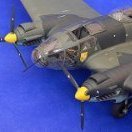
almost done. I need still to add some pigments and exhaust soot I have used neutral grey (MIG) and different tan shades (AMMO) for panle line wash finish with mixture of matt and semi matt MRP varnish wheels exhausts thanks for looking jan15 points
-

1/32 Eduard Messerschmitt Bf 108B Taifun KG + EM Libya 1942
Rocat and 11 others reacted to monthebiff for a topic
Recieved this during last week and just wanting a pretty simple OOB build I decided to crack on with it. After looking over the sprues it definitely has the feel of a short run kit with detail generally being a little soft in most area's. A nice little PE set is included as well as canopy masks and a resin prop should you choose to use it. The Argis engine built up nicely but didn't spend to much time over it as not much will be seen. Also managed to get the cockpit floor built up this morning ready for some colour to go on. Also had a fit of the main fuselage halves and glad to say it's a pretty good fit as is the rest of the kit so far. Regards. Andy12 points -
1/32nd scale Avro Shackleton - scratchbuild project
RLWP and 8 others reacted to tomprobert for a topic
Still plodding on with the making of interior parts... The basics of the pilots' seats is now done (plasticcard and Milliput) - still some additional details to add such as the trim wheels etc. but you get the idea: Untitled by Thomas Probert, on Flickr I've also made the two control columns - I used the part in the HK Lancaster kit as a guide as they're more or less identical in the Shackleton MR2. An old paperclip, some Tamiya tape and various bits of Evergreen was the order of the day here: Untitled by Thomas Probert, on Flickr Hopefully I'll get a splash of paint on these later. Regards to all, Tom9 points -
Finished! HPH Mig-15 Korean War
Starfighter and 8 others reacted to Padubon for a topic
This is how the thing looks: Let the nightmare begins! Tons of photo etch.9 points -
evening folks a bit more done over the bank holiday... I started to work on the left hand side console as seen below - I don't have a drawing of this side so I made one from scaling multiple pictures, made tricky by the oblique nature of the photographs - note also the oval pressing shapes which would need reproducing... ..I made up a female shape as I did with the first side, but I couldn't get happy with the results - the metal curves into the hole rather than the sharp lines seen in the photo - I tried annealed (left) and non-annealed metal, but both were a fail.. so I used the drawing I made to generate it in 3D and will just add a metal side plate and fair in the join - here is the pre print image Tim sent me.. you can see the console on the left and the other bits are the artificial horizon as thats quite an iconic part (& cannot be done in etch) and the Ausgleichsgefäss that sits unfer the main panel in the one cockpit photo I have.. ..so while that gets printed I moved on to sorting the fuselage around the cockpit.. ..I scaled the Bentley drawings and marked the key lines of the rear bulkhead & floor.. ..then I cut out the sides and added scaled templates again from drawings to make sure the bulkhead shapes were correct - they were out quite a lot - the rear especially was flat sided and too narrow compared to the template so the first round of P38 filler was added to start to bulk it out.. ..once that was done, the canopy area was checked, again this was a bit out with the angle being wrong (too tall at the back), too low, and the 'footprint' shape being too fat at the rear - I started by correcting the angle to the right one.. ..then a scaled template added to make up the height and give the correct shape - I added a brass sheet tip so I didn't sand away the right shape... ..another set of templates added and the whole lot filled with P38... ..and after shaping & priming, I know this bit is right... ..also made double sure the front was right.. ..I also added the nose bit (not the cowl) and tried to replicate the unique top cowling area the V18 had - it is not the same as any A or D model so all I can do is work from photo's - it's not finished, but it's closer than it was.. ..I now had made enough changes to start to set out where things go by using the drawings to give me a scale skeleton of major reference points.. ..I will start with the sidewalls, so I cut some litho sheet that overlaps slightly front and back and made a jig for the sheet to sit in - this is both sides, on the right is the carrier, a sheet that the actual sidewall will sit in that matches all the cross section drawings and on the left a sidewall is sat on it's carrier with the areas that will overlap the fusealge taped up so I know the boundaries of the space to work in.. ..it's this sort of principle - I can keep taking the sidewalls out of the jig to align with parts etc and build up the detail until at some point they get mounted - I can then just skin over them.. TTFN Peter8 points
-
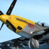
Getting closer and finding that my long layoff from building (work, travel, moving...) has seriously eroded my skills. I've painted and repainted due to not doing things in the right order and I have a LOT of seam clean-up still to do. But I'm getting a lot better at cleaning up canopies (since Tamiya has that nice seam right down the middle to deal with...). I also think I didn't trim the canopy floor enough to deal with the Barracudacast resin sidewalls as there seems to be some stress in the fuselage. The EagleCal decals responded extremely well to MicroSol but did NOT like to be moved or adjusted very much. The fuel caps are painted. The red is Vallejo Red, the Olive Drab panel is MRP over white Vallejo primer. Wings are a mixture of Vallejo Metal Aluminum and Vallejo light gray. The yellow stripe is also Vallejo yellow over a dusting of Vallejo white primer. Fuselage and the panels by the exhaust are Vallejo Metal Color over Vallejo gloss black primer. The Prop is simply Vallejo Black Primer (and Tamiya decals). No over coat yet on the aircraft, but will hit it with clear flat here shortly...(and THAT's why I should not have taken off the windscreen masks - blast!). What is interesting is that almost nothing on the bottom of the aircraft is glued on. The landing gear is screwed on, and the landing gear doors are a press fit (and a very tight one at that! And the drop tanks will be attached with magnets. Tires are the resin Barracudacast set. Nice detail on the wheels. Everyone have a good Sunday and a Happy Mother's Day! Chris8 points
-
Make the others jealous
LSP_K2 and 7 others reacted to thierry laurent for a topic
Call me crazy but I just purchased a 1/32 AC-47...! I know the HpH kit is not easy to build but... I got a 50% discount on the retail price whereas the kit has AMS miniguns and a big additional photoetched nickel set with close to 150 custom parts covering the cockpit door, gun baffles, supports and so on! It also has the flaps! The prior owner had just glued some internal parts... I never thought I would get such a kit!8 points -
1/35 KH MH-60L "Super 63"
dodgem37 and 6 others reacted to Hawkwrench for a topic
I finished up the right side cabin sidewall tonight. Also, I did a little more work on the cabin roof. I like the way it's turned out except for the left cabin light. I'll have to fix that tomorrow night. Tim7 points -

Digital Fulcrum:
scvrobeson and 6 others reacted to Martinnfb for a topic
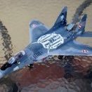
beauty ! here is another hi-res motivator7 points -
Thanks guys! One of the tougher builds I've encountered but I'm definitely over the hump and it should be more of a downhill glide rather than the uphill slog I've had to deal with. Alan...like most of my large scale builds, this one is for a commission. I just don't have the desire (or room) to store my completed models. I've got a coat of primer on her. Very light and uneven... just wanted to get a look at the all of the surface fixes, panel lines and rivets and make any last minute repairs before I start painting. One area needs some attention...7 points
-
Almost done with this one now despite not modeling too much during the last week. Nozzles assembled And fitted Cockpit done. Tomorrow a few touch ups and a base, then she should be complete. Then re-arranging the display case. Cheers Nick7 points
-
Even though we've all seen this plane done dozens of times, it's always been one of my favorites, so here's mine all finished up. Details: Hasegawa ST19 kit Eagle Editions "Yellow 10" decals for specific markings and swastikas HGW wet transfers for national insignia and most stencils HGW seatbelts HGW wood decals for flaps Aires wheel bays and cockpit Airscale instruments and placards (thanks, Peter!) Grey Matter Figures (Rutman) D-13 conversion set S.O.W. main landing gear legs (thanks Damian!!) Eduard exterior PE bits and canopy masks Barracuda wheels Moskit exhausts (thanks WilliamJ!) Wire antennae, brake lines, brass tube gun barrels Homebrew washes and chalk weathering Thanks for looking! Tim6 points
-
HH-60G Pavehawk Kitty Hawk 1/35 DONE!!
Starfighter and 5 others reacted to Pete Fleischmann for a topic
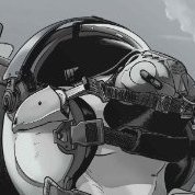
Hey all! big day today! Actually put glue on the pilots butts- Also put some pegs in the crewchief ‘s knees that fit into holes in the floor ...Remembering that this will be an inflight display, here’s where I’m going mit dat- cheers Pete6 points -

F 116 what if
Loach Driver and 4 others reacted to red baron for a topic
F 100 +F 16 = a relaxing montage without taking yourself seriously :5 points -
OK, last one guys, I swear. This is my COVID-19 quarantine build and I'm pretty happy with the way this one turned out. As with the previous three, no real weathering to speak of and built mostly OOB with exception of HGW seatbelts in addition to the Vickers and double Lewis guns courtesy of Eduard Brassin. Sorry I didn't get any pics of the underside - I'm too damn scared to flip it upside down! As I mentioned in the introduction for the Junkers D.1 build I posted earlier, I'm really not at the point where I build for historical accuracy so this bird has features that were not included on the "IF" scheme outlined in the manual (wheel covers and double Lewis guns). These recent WNW builds are all going into the display case for basically only me to look at so I decided I can live with it because I like the way it looks! I think I told myself when I was building it that I would build the next one to a much higher historical standard (and actually do a WIP!) but that was before recent developments... Anyway, on to the pictures. OK, I swear I'm done now... Anyone have any ideas how I get these safely from NYC to California?5 points
-
Onto the engine, which is engineered very well. Everything fit as it should. A little trick I learned doing paste-up when I was a graphic artist. Bestine for cleaning plastic. Drop the parts in a jar, swirl it around and done. I painted the cylinders AK Xtreme Metal aluminum and did a wash with AK Engine and Turbine wash. Next time I’ll use their White Aluminum, this looks a bit too shiny. Exhaust is painted with AK Xtreme Metal Burnt Metal. Also randomly painted some rust color. It’ll do especially because you can’t see any of the exhaust once the engine is installed. Firewall, engine mount and more stuff you can’t see, but I need more paint time. Primed with black and randomly painted over with zinc chromate. Doesn’t really look that yellow. Engine assembly complete. I actually managed to drill out the ignition harness and wire with .015” lead wire without messing it up, something I could have never done before my cataract surgery. If you’re contemplating having cataract surgery done…. Just do it! It’s life changing. Not having learned my lesson regarding PE I decided to add some details to the guns. The problem I always have with PE is that it often covers places where other things go. In this case, the armor shields had to be modified to fit. You also have to remove the breech ch arging handles and re-attach them to the PE. Nerve wracking for me anyway. Also added Master brass barrels which by some miracle came out straight and plumb. After I put it all together I have some touchup to do. Guns painted dark neutral gray with old school graphite shine. Wish I had paid closer attention to the gun barrels, my OCD tells me that the cooling holes should both be on the top. Next time. That’s all for now. Next installment will be the gun mount and rear cockpit details. Thanks for looking. Comments and constructive critique is always welcome.5 points
-

Focke Factory II
Kais and 4 others reacted to Bruce_Crosby for a topic
Hi Guys. After a two year break from this project, I think I'm just about ready to resurrect it. Numbers have grown from six possible kits to EIGHT! Plus, of course, a few Ta-152 kits by Zoukei-Mura and PCM. I was distracted by other projects like the 1/32 Me-262 He-162 Mistel and some sci-fi stuff! Regards, Bruce Crosby5 points -
Beginning work on the cannon and ammunition bays........ Dan5 points
-
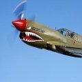
Still in the final stages of wrapping up the last project, but I can't help starting to fool around with the next one. This will be the counterpart to my recently-finished AVG P-40B. The IJAAF 77th Hiko Sentai was created in 1938 by reorganization of the IJAAF 8th Hiko Daitai, and was initially deployed to Manchuria, and later to central China. They were initially equipped with the preceding group's biplane fighters (Type 95), and began converting to the new monoplane Ki-27 in late 1939. At the beginning of the Pacific War, when Japan moved to secure the "Southern Resources Area" (i.e. to conquer the Philipines, Maylaya, and the Netherlands East Indies to obtain their vital oil and rubber reserves), the 77th was redeployed first to Southeast Asia. When it became apparent that Vietnam, Cambodia, and Thailand would not oppose the Japanese invasion, they moved onward to the Burma front, where British and American volunteer forces were attempting to halt the Japanese advance. The 77th tangled with both AVG Warhawks and RAF Brewster Buffalos throughout the opening months of 1942, and while the aerial battle was by no means one-sided, with both Allied and Japanese pilots claiming multiple victories, the land war was ultimately decisively won by the IJA, forcing the AVG to retreat to bases in China, and the RAF to India. This is the kit in question: Prior to the start of the Pacific War, most IJAAF fighter aircraft were painted overall light gray. Once the various Sentais deployed to Burma and New Guinea began to encounter significant resistance, and in particular resistance capable of mounting bombing and strafing attacks against airfields, they began applying field expedient camouflage schemes of green and brown (per box art above). However, this change in appearance was by no means universal or immediate, and plenty of the 77th's Nates fought above Burma in their factory-spplied gray, as shown in these familiar photos of AVG pilots inspecting a downed 77th Sentai airplane: Because I am tired of building green and brown airplanes right now, we'll be doing this one in IJAAF gray. Of note, the ID markings shown in the box top art are incorrect. While the yellow horizontal bands on the vertical tail are OK (indicating 3rd Chutai), the "seagull" shapes (stylized 7's for the 77th) should always be blue. There are again familiar photos on the internet that show this pretty well: Of note, the painting in Thorpe's IJAAF Camouflage and Markings book shows the "seagull 7's" being red. I'm going with the photo and making them blue. Looking at the B&W photos of the wrecks above, it also looks very much like the rear fuselage stripes (indicated the number of the individual plane within the Chutai) were white, not yellow, so the Special Hobby box art (and decal sheet) are wrong on that front too. This does not matter to me as I'm going to mask and paint all of the identifying marks on the plane.4 points
-

HPH FW 189 Eagle Owl.
Shiba and 3 others reacted to Phartycr0c for a topic
Progress on this build is still crawling along. I have started a second build of a Hobby Boss Fiesler Storch to occupy the time during drying times for the epoxy . It helps.... The build has progressed unremarkably right up to the point of starting to attach the glazing parts which Is where I now find that the addage of dry fit dry fit dry fit comes into play. The geometry of the various parts are critical in this aircraft as are the compound curves transitioning into the flat underside panel of the rear glazing unit. Its an attractive aircraft but unless you get all of the test fitting absolutely precise then its a complete cow to put together. I dunno if im losing my dexterity but i had parts correct one side and not the other, and vice versa, In the end it came together of a fashion. The shape is all determined by the gun ring which might be a little undersized but i'm not sure. Grinning footballer included to distract from the arse end work going on. Forgot to mention, as you can see I have completed the flap structures in prep for the final construction process. I will clean them up and pop a wash over them to bring out the lovely details. Any Hoo! having beaten the back end into submission, ( with the exception of the final cleanup,) my attention turned to undercarriage components, which again are sublime with the exception of a slight short shot where the reinforcing rod has popped through the resin casting. No big issue but to try and cover it over would make the offending UC leg horribly thick in appearance so I'll leave as is and camouflage it best I can. Excuse the yellow hue to the photos, whit balance dont you know.... Then on to the next issue which certainly isnt of my making. The centre section of fuselage between the two sets of glazing is slightly out of profile, almost squat in its appearance and therefore not wide enough to span the fuselage gap. Reading Jan Gauber's build article, he encountered exactly the same problem which required the part to be built up using several shims to compensate for the difference in height between the front and rear glazing parts. The following photos hopefully illustrate the issue. You can see the gap between the edge of the upper fuse part and the fuselage sidewall, its meant to be flush. Shim and packing city beckons! Finally I would like your opinions on the below photograph. Taking into account the scheme I am looking to complete I have been experimenting with various methods to achieve the "squiggle" pattern. Airbrushing was NOT successful, the airbrush needs to be at 90 degrees to the subject at all times and there are far to many curves on this beast so I failed. The best I could come up with is an acrylic paint pen in pale green (rlm 76 ish). I had a squiggle session on the painted engine nacelles and while it looks a little bright I will tone it all down with a filter and wash. Its probably the best solution to my issues but I would like to know what you guys think.4 points -
Hello, my last model aircraft in 1:32 scale Ki-44-II HEI Shoki (Tojo), kit Hasegawa ST30 and P-38 J Lightning, old kit Revell 04741. Thanks for watching.4 points
-
Tim, it is what I enjoy the most and do best. Painting, superdetailing, weathering, I always seem to come up short. But I can grab your attention with an unusual subject. Dan4 points
-
The gun gasses streak along the bottom of the jet. When they're downrange, they do get exquisitely filthy. I was around the Boise Hogs when they came home from the sandbox a couple years ago. It was so awesome. They took great pride in their dirty Hogs. Jake4 points
-

1/32 Messerschmitt Bf 108 'Taifun' by Eduard
MikeMaben and 3 others reacted to Rick Griewski for a topic
The kit came Saturday. I will clip it off the sprues and tape it up Today. BTY I am glad I bought the resin spoked wheels. Rick Box open, cutters flailing and with tape in hand. I am very happy with the kit! Highlights for me: — external seams will need no filler except where the center wing belly meets the fuselage. Wing root is well done. — clear parts are well done. I like the closed or open canopy option and painting masks — resin prop is lovely — PE looks great and it looks to be useful over all. — great selection of ac to portray. Challenge: — some fragile parts — landing gear will be weak — I replaced spokes wheels, the tail wheel is mush — plastic has texture that with require primer IMHO I will order another kit and resin wheels4 points -

ZM Hs-129
Uncarina and 3 others reacted to Troy Molitor for a topic
I’m sorry, but it’s a rather lame marketing decision to release a kit with “ one” limited regional decal option. I’m likely the only one, eh? Yep, semi disappointed but nonetheless I am looking forward to a Russian front version. Sooner rather than later is an understatement.4 points -
And my house is older than your country!4 points
-
Hello, Follow images of my newest model. It is a Revell kit (Hasegawa mold) assembled out of the box except for a set of Eduard seat belts. The painting was done with Gunze Sangyo Mr. Color paints. I hope you enjoy it. Hugs.4 points
-
Only a small update today. The secon seat recieved its decals. THis time I went with a hotter decal solution (Mr. Mark softer insted of Micro sol) and it definitely helped to get everything in place. It lloks just like the other one, so a photo seems unnecessary to me. I turned my attention to the side consoles and aded the Anyz decals. Oh boy that was a hard fight. You have to get them centered to the 0.5mm hole - easy peasy if the surface is flat. Well the side consoles aren't.. They aren't as perfect as Pete's work on the pave hawk but good enough for my first try. Decalling isn't over but I have to wait until the new Airscale instrument decals arrive. I ordered them thursday and they are already in the mail. Those brits are fast! I started working on the electronic bays. It was mostly removing plastic for the eduard PE. I thought I could rush trough but there are loads of cables which need to be added. I started losing my mojo. So I stopped (no photos yet) and went on to work on some plastic. I never thought that filling and sanding seams on drop tanks could be therapeutic4 points
-

How dirty does an operational A-10...
Landrotten Highlander and 3 others reacted to Finn for a topic
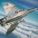
Even F-15Es get dirty: Jari4 points -
1/32 Lockheed U-2A?
chrish and 3 others reacted to D.B. Andrus for a topic
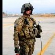
I believe "The C-130's" band wears cargo pants.4 points -
A couple of the guys over at LSM asked my thoughts on the HGW wet transfers I used for the first time on my FW190D-13 build, so I thought I'd share my answer over here, too, in case it can help someone. This was my first time using them, and I loved them! Here was my procedure, based on the instructions: 1. Cut out the transfer with about 1/16-1/8 inch of space around it (so you have something to grab later with the tweezers when removing the carrier film). As with decals, a glossy surface is best, but I found that these things would lay down well even on a pretty matte surface using this method. 2. Dip the transfer in WARM water for about 10 seconds, enough to soak the backing paper, and remove. Lay it on a surface that won't soak away the water and let it sit for maybe 20 seconds in it's puddle, but don't give it too much time to cool off - just enough time for it to get loose on the paper. (Water that feels almost hot to the touch worked best, maybe 120 F. Not painful, maybe like the water most people would shower in) *Note: the instructions recommend setting solution from Mr. Hobby, I think, but I didn't have any of that, so I used the old Microscale products, shown in the picture. I even labeled them 1 and 2, so I would not forget what order to use them in. 3. Apply some Micro SET (NOT Micro SOL) to the surface where the transfer is going. This was new for me, since I use only Micro SOL for decals. But for these things, BOTH products seemed to be needed. Micro SET is the one with the blue writing on it, and it softens the material and improves adhesion, but it's a weaker solution than the Micro Sol, and is less likely to mess up the carrier film or the transfer. Do NOT use Micro SOL (red label) until AFTER you remove the carrier film later. 4. Dab some water off the transfer, then slide it off the backing paper onto the surface with the Micro Set on it. Position it and press the liquid out from under the film with a decal squeegee, paper towel, cotton bud (Q-tip), or such. I'd leave a little so you can do any final positioning before pushing it all out. For bigger transfers, I slopped on a second coat of Micro Set under the edges of the film and pressed it out again. The film is very thin and clear, but strong, so it's easy to position, but it can curl back on itself just like a decal, so take care. **Here's an important note: If you realize that you buggered the position after you press out the liquid, get some water worked under the film with a paint brush ASAP to dilute the Micro Set and break it free before it adheres, which it does damn quick! Then reposition it, work some new solution under it and repeat the process. 5. The instructions say to wait 3-4 hours for it to dry before removing the carrier film, but I found that many of the transfers, especially the smaller ones, were dry enough to peel the film in 30 minutes, and even the bigger ones only took an hour or two. If you think it's ready, carefully get a grip on the corner of the glossy film with some tweezers and peel it back slowly. Obviously, if the transfer starts to come up, STOP, work a dab of Micro Set under it again, re-squeegee, and wait longer. I found that slowly peeling the film back parallel to the surface, rather than pulling straight out and away, reduced the chances of lifting the transfer. 6. After the film is removed, you can apply Micro SOL (red label) to the transfer, just like you would to a decal, dab off the excess, and let it dry. I found that these transfers even laid into panel lines and details without poking or cutting usually, but once in a while it still helped to poke a hole and let some Micro Sol get in there to help it out. The Micro Sol has the added benefit of breaking down all the leftover adhesive, so I gave each one a final wipe with some on a Q-tip after they were good and dry. It's important to get that adhesive off, because it will cause weathering chalks and washes to behave oddly in that spot. The instructions say to use water to do this, but I found it really didn't get it all off as well. Once these transfers are good and dry, I found they are tough as hell, way tougher than any decal. In a couple test cases, I even tried lightly sanding on them with fine grit paper to see if they would peel off, and they wouldn't without some good pressure. I wouldn't suggest taking that too far, though. They are almost like painted on markings. I chipped them just like paint, and they held up great. All in all, I found them a fantastic product, and will use them again. Hope that helps!! Tim3 points
-

Belated 1/32 Trumpter Harrier GR7
johncrow and 2 others reacted to Orfordness for a topic
next was the front nose replacement Piero#s master for the new nose A little fettling and filling followed by re-scribing (some too deep ) of the adjacent panel lines... Around this time I was also lucky to pick up a pair of Tim Perry's CBLS100 Practice Bomb carriers Prior to varnish and decals:3 points -
Ki-43 "Hayabusa", 1:32, Hasegawa
MikeMaben and 2 others reacted to Hartmann52 for a topic
3 points -
I've managed to paint and shoehorn the pilot into the Lightning cockpit.....no I wasn't in the least bit tempted to paint the helmet in the 56 squadron chequers! I do need the tidy the front of the helmet up a bit where some black paint "flooded", and the figure painting isn't of the highest calibre by any standards but: ....under the canopy not a lot can be seen anyway! He's sitting a little bit high for my liking but I can't get him any lower and the canopy does shut, just, so that's OK by me!3 points
-
Lothar, I would say the only subjects worthy of a scratchbuild. Dan3 points
-

Infinity Models SB2C-4 Helldiver update
Rick Griewski and 2 others reacted to LSP_Mike for a topic
A mole from Tamiya.....3 points -
in the same way it's always funny to hear Americans talk of 'history' and things being 'old'... everything is relative old chap3 points
-
Living in Thailand got me a differents focus on Air Battles. Joined a group build on Aero Scale for the CIB. First time I build a Japanese Aircraft. good memories. Also with the same research on wings, color and those special markings that drove the western guys mad... My build of a late war Frank. All of a sudden you realize it was all very close to where you live. Visits to the landmarks however are rather disappointing in Thailand. They hardly recognize history, sad but true. It's a period and specific war scene. Like with The Netherlands East Indies, very interesting material. Following with interest. Robert Jan3 points
-
Still alive and kicking thanks!! My Lightning-attention has been slightly deflected of late by this: Blame Lothar, he made me do it!! Back on track with the Big Boy soon!3 points
-
!THE FOLLOWING IMAGES COME WITH A PUBLIC HEALTH WARNING AND SHOULD NOT BE VIEWED BY THOSE OF A DELICATE DISPOSITION! Following my late decision to turn the Lightning into an airborne model, some radical surgery butchery was required to remove the 25g of nose weights. It's not pretty, it wasn't clever but it worked: though with collateral damage. Airfix made no concession when designing the kit for those wanting a wheels-up plane so each piece of the wheel covers had to be jigsawed into place and on the same "plane". This was achieved with varying degrees of success by the judicious use of Blu-Tak! So with a little more attention to cleaning up, she'll be ready for a coat of primer. I had sadly to amputate the pilot's feet to get him into the cockpit at this late stage. The weather's breaking up a bit so I plan to be at the bench this afternoon for more fun.3 points
-

Best place to live in the UK
Astro32 and 2 others reacted to Dpgsbody55 for a topic
Where would I live in England?? My family left England when I was 12 and I was so glad to get away. That was 1967, and we'd been through a lot of family problems in the previous year, and I never wanted to see the place again. Come September 2015 and my wife, who is from south Devon, organised a trip back. I didn't want anything to do with it and just went along to keep her happy. We arrived at Heathrow at about 6pm and checked into our hotel nearby at 8pm and settled down for the night. The next day, we picked up our rental car and headed for Amesbury for our second night, and Stonehenge, which I remember visiting, and climbing all over, when I was about 10. As we drove along, I thought "this is great!!!" Such wonderful history, so much scenery and nowadays, so many interesting car and plane museums, etc. As we walked from the car park to Stonehenge, we were picking wild blackberries, like we used to as a kid at that time of year. On the whole, the trip was wonderful and I had a great time. We had another trip organised for this year, but you know what's happened to that now. The worst day, from a touring standpoint, was when we went from Plymouth, following the coast, to Newquay, which is about 100 miles. It took all day, literally, and even the main roads through Cornwall get choked up with traffic, thanks to the local farmers driving their tractors around at 20mph if your lucky, and nowhere to overtake. Next time, we won't make that mistake again in our holiday planning. Where I now live, driving 100 miles is nothing at all. I've driven 600 miles in a day, and still had time for coffee and lunch breaks, photo ops etc. And I''m still in the same state. On a fine sunny day, the English countryside is the best place in the world to be, in my opinion, but would I live there again?? Oh hell, no, but I'll be back for another (long) holiday. The weather is a lottery, and you can keep the winters. I have too many memories of the cold and snow living in the Cotswold Hills in my younger days to ever put up with them again. Yet I know I'm missing out on a lot because of that decision. Living in the countryside is wonderful, but I would never live in the cities there. If I had to choose a place to live there, it would be the north Devon or Cornwall coast, of which I have many happy memories of holidays spent in that area, and I still loved it when I was back in 2015. The area is not so good from the standpoint of museums etc, but there's ways and means around that problem. But the Aussie lifestyle and climate is too big a draw for me to want to live there again. BTW, I've spent a few months in the USA too, and love that. Perhaps I should consider myself a citizen of the world, as there's so many wonderful places too. Cheers, Michael3 points -
I also recall my uncle's funeral there. My mom and I wanted to join my aunt and cusins to spread his ashes somewhere near Newquay (can't remember the name) then head to Heathrow for an early morning flight to Germany for work. We were leaving from Cowbridge Wales where we had the funeral. We never made it, had to turn around and head to Heathrow or we would likely not have had much if any sleep. It doesn't look far on a map but that is a LONG drive3 points
-
I've driven all over England, Wales and Scotland many times over the years. Even though the entire country is only 7/8 the size of Alberta it can be a difficult to get around quickly in some areas. I recall one trip driving from Heatherow to Poole then up to Cheltenham, it took FOREVER. We can drive almost the whole length of Alberta in about 6-8 hours or so, that trip took about the same if I recall. Very pretty part of the country though.3 points
-

1/32 Nakajima Ki-27 - 77th Sentai - Burma 1942
Rick Griewski and 2 others reacted to Alex for a topic
Stuff I've read that's relevant to this build (and CBI theater in general). All interesting history and the last three very useful model building references.3 points -
HH-60G Pavehawk Kitty Hawk 1/35 DONE!!
Sepp and 2 others reacted to Pete Fleischmann for a topic
Hi all, getting closer on the pilot seats! The carabiners still need to be strapped in. the chem light glow sticks are just Evergreen rod, with one end pinched flat with a flat nose pliers, then a little Tamiya clear green- the first aid kits are Live Resin items, with markings from Archer- dry transfers that I made into decals. The intercom panels need some markings; but man they are small! We’ll see I guess- the seat frames need some dust too- cheers Pete3 points -
I would welcome you as my neighbour Tim but to see how I do stuff you don't need to move next door - I regularly post videos on Patreon - 2 this week on making up that side console and what I have been doing today on the cockpit - it's but a few bucks a month to access and it is going to a good cause - ie back into modelling Indeed the Mustang It sits here waiting for my local plastics shop to re-open so I can get the display box made and actually finish it - I have some fabulous drop tanks & hangars that Steve at Model Monkey 3D printed for me and I hope if Telford goes ahead to take it there onwards & upwards lads TTFN Peter3 points
-
Finished what I consider the most formidable fix that I will be applying, so I am a happy lad. Close enough for government work! Cheers, Tom3 points
-
1/32nd scale Avro Shackleton - scratchbuild project
D.B. Andrus and 2 others reacted to Derek B for a topic
Great work as always Tom - I am very impressed with your scratch building work. I think that an MR.2 would look awesome. I know that the Shackleton GR/MR.1 and early MR.2 aircraft used the same dorsal armament as the Avro Lincoln (I am making a kit master pattern of the Lincoln at the moment, so that is how I know). The dorsal turret is a Bristol B17 turret armed with twin Hispano Mk.V cannons. Below is a quick trawl of the internet for relevant reference material for you Tom: Installation on a Lancaster The Bristol Aeroplane Company Ltd The Bristol Type B.17 Mk.1 Mid-upper Turret - Pt 1 Nearly all the Bristol designs produced by the Company were mid-upper turrets intended for aircraft use. The last Bristol turret to be produced in quantity was also a mid-upper design, the Type B.17. However, this was for the Avro Lincoln. In 1943 the Air Ministry issued a specification for a Hispano-Suiza cannon turret for the new bomber . It called for a high degree of control and had to be as self-contained as possible. The Boulton Paul and Frazer-Nash companies submitted updated versions of cannon-armed turrets designed in the late 1930s, but the new Bristol turret proved superior and was accepted for use. The main reason for this decision was the advanced power system built into the turret, the Bristol all-electrical system. The prototype of the new turret was constructed at the Carson factory, where the production jigs were also produced. The turret was a self-contained unit supported from the aircraft structure by a top bearing, the outer part being fixed to the aircraft frame. The inner rotating section formed the turret ring from which various sections were suspended; these were the gun cradles, the armoured front shield, drive motors and control console, and the ammunition boxes, seat and rotating service joint. Roller bearings took the side and upward loads, and steel balls supported the main weight of the turret. The B.17 was powered by the Bristol all-electric system. the motor/generator unit was strapped under the floor, and the two drive motors were fixed vertically to the armoured shield in front of the gunner. As in the B.12, the traversing drive motor turned the turret by means of a pinion engaging in a toothed ring bolted to the outer fixed ring of the turret rotation bearing. A spring clutch between the reduction gear and the motor - was designed to slip under excessive loading. The gun cradle was elevated and depressed by a drive motor which turned a screwjack attached to the hinged cradle, and the elevation drive was also protected by a slipping clutch. The turret drives were controlled by a twin-handle controller which varied the speed and direction of the drive motors by means of potentiometers in the twist-grip handles. The handles were also fitted with grasp-type levers which operated switches to energise the field circuits of the generators, the levers acting as dead man's handles. On the top of the left handle was a high-speed button - when this was pressed the drive motors could be operated 30 per cent faster than normal. This facility could be used only for short periods, and was used to change quickly from one target to another. The main electrical supply was taken from the aircraft bus-bars. It was switched on by operating the button of a circuit breaker mounted outside the turret in the aircraft fuselage. A similar breaker was mounted on the gunner's control console. The current entered the turret by way of a rotating service joint at the base; the service joint consisted of a circular drum with three sets of brass slip-rings for the intercom system, general electrical services and main power supply. The drum rotated with the turret, and carbon brushes in contact with the rings took the services into the turret; oxygen was supplied by a pipe running through the centre of the drum via a rotating union. The two 20 mm (0.78 in) Hispano cannon were mounted on special cradles with built-in recoil mechanisms. They were connected by a substantial torque tube which rigidly connected the guns in traverse. Until this time the gunners had cocked their Brownings with a rope lanyard, but with the massive Hispano return springs this was impossible. A compressed-air gun cocking unit was therefore employed, supplied from an air bottle in the turret. The gun cradles were designed to accommodate either the Hispano Mk.IV or Mk.V cannon mounted on either side of the seated gunner. Ammunition was stored in boxes which also supported the gunner's sadle-type seat housing. Each gun was supplied with 350 rounds, sufficient for 30 seconds' firing. From the boxes, the ammunition belts were lifted by electrical feed assisters mounted on the side of the gun housings, the rounds being channelled through chutes into the gun feed mechansism. The ammunition feed system was to cause much frustrating delay in bringing the turret into service. It was found very difficult to synchronise the speed of the assisters with the feed mechanisms. The fault was finally rectified, but even after acceptance for Service use this was still the main cause of stoppages. Empty cases and links were ejected into canvas bags slung on either side of the turret. A feature of new British turrets was the provision of ammunition round counters, two dials mounted on the gunner's control console giving an accurate indication of rounds available. This was thought necessary owing to the relatively short supply of ammuntion available. The guns were fired by triggers on the control handles. When these were pressed an electrical circuit was closed which energised two relays. These in turn switched current to solenoids which activated the firing mechanisms on the Hispanos. The gun-firing circuit was wired in series with a Bristol drum-type gunfire interrupter mounted between the drive motors. When the gun barrels approached a position where damage to the aircraft might be caused, the circuit was switched off. The above text and photos were taken from "British Aircraft Armament Vol.1: RAF Gun Turrets", by R Wallace Clarke. ATTACHMENTS Elevation drive unit.jpg (36.12 KiB) Viewed 2026 times Bristol Type B.17 in test rig.jpg (50.62 KiB) Viewed 2026 times Wooden mock-up of Bristol Type B.17.jpg (50.54 KiB) Viewed 2025 times Top The Bristol Aeroplane Company Ltd The Bristol Type B.17 Mk.1 Mid-upper Turret - Pt 2 The guns were sighted by a Mk.IIC gyro gunsight, mounted on the torque tube between the gun cradle brackets. The range input pedals for the sight were situated on extensions to the gunner's footrests. The turret was surmounted by a low-drag cupola which provided a good field of view. The long gun barrels protruded through vertical slots fitted with draught excluders and curved panels which moved with the guns in elevation. The rear half of the cupola could be removed to release a trapped gunner, and to service the guns and turret mechansism. The gunner's saddle-type seat could be adjusted for height and reach to any one of six positions by the operation of a lever at the back of the seat. The interphone system to the rest of the crew was switched on by means of a 'press to speak' button on the right control handle. Oxygen and heated clothing sockets were provided. Although the back of the cupola could be removed, the gunner's emergency exit was through the aircraft, his parachute being stored on the port side fuselage wall. The oxygen economiser unit was fed from the rotating service joint, a flexible tube being taken to the gunner's control panel where a flow indicator was fitted. Details of the Bristol B.17 Mk.I Mid-upper Turret Position: Mid-upper Armament: Two 20 mm (0.78 in) Hispano Mk.V Ammunition: 350 rounds per gun Fire control: Electrical solenoids Field of fire: Traverse: 360 degrees Elevation: 45 degrees Depression: 10 degrees Full load current: 140 amps Gunsight: Mk.IIC gyro sight Weight of turret (armed): 656 kg (1,445 lb) Diameter of ring: 94 cm (37 in) Overall height: 94 cm (37 in) Cupola height: 64 cm (25 in) Armour protection: 10 mm (0.393 in) Speed of operation (Normal): Traverse: 0-35 degrees per sec Elevation: 0-25 degrees per sec Speed of operation (high speed): Traverse: 0-45 degrees per sec Elevation: 0-35 degrees per sec The following aircraft were fitted with the Bristol B.17 Mk.I Mid-upper Turret. Aircraft type: Avro Lincoln B.Mk.II, Avro Shackleton MR.Mks. 1,2 & 3, Short Seaford Mk.I Position: Mid-upper Guns: 2 x 20 mm (0.78 in) Mk. IV or V Traverse: 360 degrees Elevation: 45 degrees Depression: 10 degrees Remarks: The above text and photos were taken from "British Aircraft Armament Vol.1: RAF Gun Turrets", by R Wallace Clarke. ATTACHMENTS Bristol B.17 turret.jpg (33.71 KiB) Viewed 2019 times B.17.jpg (32.47 KiB) Viewed 2020 times B.17 ammunition system.jpg (32.27 KiB) Viewed 2020 times Bristol B.16 nose turret The Bristol Aeroplane Company Ltd The Bristol Type B.16 Mk.I Nose Turret In 1943 the U-boats of the Kriegsmarine decided to remain surfaced and use their multiple 20mm and single 37 mm weapons to fight attacking Allied aircraft. Initially the practice was successful and many Coastal Command aircraft were lost. The problem was that the front turrets of the Sunderlands, Wellingtons and other types were armed with 7.7 mm (0.303 in) rifle-calibre guns and the Germans knew they had 1 km (0.7 miles) during the attack when the aircraft could be not return their fire. The small Brownings, sometimes only a single gun, had a maximum effective range of some 549 m (600 yds), much less than the heavy calibre AA guns of the U-boats. The Air Staff were naturally concerned,and meetings were held with the various aircraft and armament companies to find a method of countering the new and potentially disastrous situation. One of the many schemes suggested was to mount a 40 mm (1.57 in) Vickers Type S gun in the nose of Coastal Command aircraft. The front fuselages of the Sunderland, Whitley, Hudson and other types were not suited for such a project, but there were several squadrons of Boeing B.17 Fortresses serving with the Command. The Bristol Company was given an order to design a turret suitable to mount an S gun, and adapt a Fortress to take it. A Coastal Command Fortress (FK185) was flown to Filton, and one of the huge guns was sent from Vickers' Crayford works. Work started immediately. It was decided to use the newly designed all-electrical power system, and a working mock-up was constructed at Carson's factory in Bristol. which was used by the Bristol Armament Department for development of new turret designs. The gun was mounted on a substantial cradle, supported by trunnions suspended on bearings in a lantern-shaped housing. The housing, or main turret body, was traversed by means of a motor which drove a geared sprocket, engaging in a toothed quadrant at the top of the turret. The turret was suspended on two roller bearings at the top and bottom of the housing. The rear of the turret housing was cut away to give access to the large drum magazine and services. The gun cradle was elevated and depressed by a worm gear working through a reduction gear and clutch. Both control motors were operated from control handles in the glazed nose position; the gunner knelt in position and sighted the gun through a Mk.IIIA reflector sight, linked by a moving rod system to the elevation gear. The gun was cocked by a compressed-air system, the magazine holding 15 rounds, which could be reloaded from a 30-round ammuniiton box in the fuselage. On the right wall of the fuselage was a G.45 camera and footage indicator; the camera could be fitted to the gun cradle when needed. In the same position was an oxygen socket and an indicator lamp showing when the motor-generator was running. When the prototype turret was installed in the Fortress the control system was found to be remarkably efficient. Vickers' liaison engineers tested the gun mounting, and the first air firing trials were organised. On 26 June 1944 the aircraft was flown to Llandwrog where a beached and derelict coaster was used as a target. Vickers' armour-piercing ammunition was fired and one shell penetrated two 12.7 mm (0.5 in) plates and one 9.5 mm (0.375 in) plate after striking the target from an angle of 40 degrees. By the time the B.16 was completed the U-boats had been all but defeated by Coastal Command, and airborne rockets had proved to be an even more effective answer than heavy-calibre guns. Nevertheless, the B.16 turret proved that the Bristol all-electric system could be adapted to suit any turret. Details of the Bristol Type B.16 Nose Turret Position: Nose Power source: Bristol all-electric system Servo mechanism: Electric motors Field of fire: Traverse: 30 degrees to each beam Depression: 45 degrees Armament: One 40 mm (1.57 in) Vickers S gun Ammunition: 15-round drum-type magazine Gunsight: Mk.IIIA free-mounted reflector gun sight The following aircraft were fitted with the Bristol Type B.16 Nose Turret Aircraft type: Boeing B-17E Fortress Mk.IIA Type & Mark: B.16 Mk.I Position: Nose Guns: 1 x 40 mm (1.57 in) Vickers S Traverse: 60 degrees Elevation: Nil Depression: 45 degrees Remarks: Prototype only The above text and photos were taken from "British Aircraft Armament Vol.1: RAF Gun Turrets", by R Wallace Clarke. ATTACHMENTS Bristol Type B.16 Mk.1 turret.jpg (40.62 KiB) Viewed 2031 times Interior detail of B.16 turret.jpg (39.3 KiB) Viewed 2031 times Bristol B.16 turet mounted on test rig.jpg (37.26 KiB) Viewed 2031 times HTH Derek3 points -
1/35 KH MH-60L "Super 63"
johncrow and 2 others reacted to Hawkwrench for a topic
So a little bit of work on the floor armor tonight followed by laying down some Africa dust where the crew chief's boots would have been while seated. Tim3 points