Leaderboard

Popular Content
Showing content with the highest reputation on 02/21/2020 in all areas
-
Managed to get the cowl installed and primed last evening, so here she is all assembled and primed. Still some sanding to do and scribing to fix, then on to the canopy!! I like the the way the thin profile of the cowl flaps looks. So much happier with it than the kit part. I couldn't get the lighting right to show the actuator rods well. I'll try again this weekend.8 points
-
Building spoked wheels: As some of you might know, it all began in 2016 with the Crossley tender build, actually I think it was one of the first builds I posted on LSP? As the Crossley build started out, only as little more than an experiment, not thinking it was doable, I didn't document the procedure... Now, for the Jasta diorama build, I wanted to retry it with the scratch building of the German Staff Car. To make things a bit simpler, I've been using the wheels from Roden's Rolls Royce Armoured Car. Making a silicone mold of the three parts for the wheels and casting resin copy's. This is the jig I developed back then, it's still the one I'm using. It's a fairly simple tool adding 24 wires x 2 to get the look of a real wire wheel. First I place a 'rim' in the middle of the jig with a axle made from 1.6mm styrene rod. Discs can be made in different sizes. I've been experimenting with various types of monofilament, but right now I'm using 0.12 mm or 0.15 mm. The 'wires' are glued to the rim with CA. A second disc is glued in place for the second part. The second rim is glued on top of the other with CA to 'sandwich' the wires between the rim parts and the second 'round of wires are mounted using the second row of 'pins' on the jig. After that I've made a disc to 'land the wires on the rim to get the right angular shape of the spokes. When the CA has dried the 'spokes/wires' are cut, leaving the finished wire wheel rim with spokes, ready for mounting. Closeup of the finished rim. The rim is mounted from the back into the wheel. The finished five wheels for the Staff Car. I know it looks quite complicated, but once you get the hang of it, it is really fast to produce this kind of simple spoked wheels. I haven't tried it on aircraft wheels yet, but if you can keep down the thickness of the rim part, this might be doable too. Cheers: Kent6 points
-
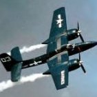
I am experimenting using only pencils and pastel chalk for weathering, no washes have been applied. All marks and scratches are copied directly from photos of in service Franks. The exhaust is too dark but I will tone it down after I finish playing drums.5 points
-
Thanks much guys! Just a small bit of progress, I completed the propeller. The blades are Quickboost "uncuffed" Hamilton Standard units, which seemed to be the most common ones used over there, although there are examples of the earlier cuffed blades and even a few Aeroproducts ones. Nothing particularly special about this assembly, given the poor conditions of the airfields, the blades would have been beaten up pretty good so I went heavy on the chipping and, (as is seen on many dirt airfields), I replicated most of the finish being worn off the back sides from the rocks and sand. That's it for today, as always, thanks for looking!5 points
-

Tamiya 1/32 F4U-1 Birdcage Corsair - Done!
Starfighter and 4 others reacted to Brett M for a topic
Thanks everyone, definitely appreciate it. More progress over the weekend. The engine cowling and flaps are done and painted. In the picture, then engine module is just stuck on, not glued in place yet so a slight gap at the top. I've also painted the white sealing tape stripes on the wings, as well as the walkways on the upper wings using Maketar's masks and Tamiya tape. I'm hoping to get a clear coat laid down in the next few days, then move onto the HGW wet transfers (lots of those!). Hoping...…. Comments, critiques, suggestions...….lay it on me. Thanks for looking. That's a big nose..... Bye bye engine work!5 points -
Thank you all very much. There is still work to be done. I am now at a cocktail bar drinking free mocktails. They refuse my money. For some strange reason people like me? I think they're bonkers. I will have dinner, then home to model. Play drums all day tomorrow. Sunday all day modelling. Luckiest man alive!4 points
-
Hi folks, Here are the latest pics of the Commander's Gun Station. The M2 is mounted and locked & loaded, T.U.S.K. 1 Armor Surround is installed as well as the Spot Light and M4 Carbine stowed. TAFN, Thanks for looking in! Barry4 points
-
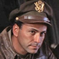
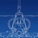
With the work on my F-100D build coming to an end, I started my next jet project. I obtained the Trumpeter A-7E kit from a local second hand trader. The kit had a few parts removed from the sprue and some minor components had been glued together (only discovered after I had purchased it and got it home). This suited me fine however, as it fit within this years New Years resolution of only building stuff that I had already started... I have a few of these in my stash that’s for sure. I felt that with a project of this size, I would try and find a subject pilot, as this is my absolute favourite way of building a kit. There is nothing better than involving a person who once flew the aircraft that I am making a model of and trying as hard as I can to make it as authentic as I can to their memories of the aircraft. There are many stories that are untold, that sometimes a project like this can impart to many people. I am very interested in the Vietnam conflict and asked the question on one of the Facebook groups dedicated to the A-7 Corsair. I was pleased to report that one such individual answered my call and it is my pleasure to introduce him to you. I asked Tom to tell me a summary of his Naval Aviation career. I entered the navy in 1965 as a Naval Aviation Cadet (NAVCAD) and earned my Wings of Gold in 1967. I initially trained on the T-34B Mentor, T-2A Buckeye and F-9 Cougar before getting orders to one of the first A-7 squadrons in 1967. I flew 98 combat missions over North Vietnam and Laos flying off the USS America in 1968. I was flying the A-7A with VA-82 of which 49 of them were night missions. During my 31 years in the navy, the first 20 years I primarily flew the A-7A/B Corsair II, A-4L Skyhawk, and F-8L Crusader. People often ask me which one I liked best and I answer that it’s sort of like women, you like the one you are with at the time best. I never flew a navy plane that I didn’t absolutely love. I was also very interested in his aviation career after the military, being a fellow airline pilot. Here is what he had to say: After I got off active duty with the navy in 1969 and went back to college at Embry Riddle in Daytona (while flying the F-8s in Atlanta Reserve squadron, I got hired with a small commuter airline flying the Beech-99s. I then flew as a F/O on a Lear-23 before getting hired by Eastern Airlines in 1972. I was with Eastern for 18 years before moving to United Air Lines in 1990. I flew and instructed on the B-727 and B737 for United and worked in the training department as a Pilot Instructor. Eventually moving to flying the B-747-400, I stayed on the -400 for the rest of my career before retiring at age 60 as a B747 captain. I then went to work as a pilot instructor and check airman for Boeing on the B-747-400 training in Seattle and Denver and then I commuted to Seoul for 5 years teaching KAL pilots. I also taught a lot of 3rd party 737 pilots (Hong Kong Air, Mongolian International Air Transport (MIAT), Asiana. My last airline job was working for 5 years as a training check airman for Evergreen Air Lines on the Large Cargo Freighter (LCF) flying and training on the B747 LCF (Large Cargo Freighter). We transported the wings and fuselage for the B-787 inside the LCF from Italy and Japan back to the states for final assembly by Boeing. Here is a pic of Tom, on active duty in 1968 And his last aviation gig a decade or so ago: Here is an excerpt from the USS America CVN-66 1968 cruise book. Tom can be found on page 309, and his good mate Kenny Fields of ‘Sreetcar 304’ fame can be found on the previous page. https://www.navysite.de/cruisebooks/cv66-68/index_028.htm Tom has signed up as a member in this forum, (callsign BURNER) and will be contributing to this build in due course. Whilst researching the Corsairs efforts in Vietnam, I saw that the earlier versions were a little different to the E and D as offered by the Trumpeter kits. I was secretly hoping that the subject pilot would be one that flew an earlier version so that I could do a conversion and I was glad when Tom volunteered (I thought in the Navy you never volunteer for anything?) that he flew the A and B model. In fact, Tom picked up brand new A models from the Vought factory and flew them in Combat with the VA-82 Marauders during the types introduction into the war. One of the ones that Tom flew from the factory now resides at the Hickory Aviation Museum here: http://nebula.wsimg.com/3e256ab57f0d2d45d9854572ca5d2193?AccessKeyId=2158F2CB6BFA6619063B&disposition=0&alloworigin=1 Some work on the kit. I obtained a PDF copy if the A/B flight manual, which I am using as my reference for most of the changes in the cockpit. I used the Aires D model resin cockpit and as a lot of the panel will be changed, the type didn’t really matter. Here is the unmodified cockpit tub. Most of the changes in this part are restricted to the right side console. I carved out some of the panels and replaced them with plastic card. next up was the Aires main wheel bays. The fit of these is extremely poor, being far too undersized. I chose one of the sides of the bay as the reference side, glueing it into position with superglue, and then epoxying in the rest of the sides. The resulting gaps. The gaps were filled with thick plastic card which I left protruding front the sides of the fuselage and then sanded smooth. I will cover the small gap on the rear edge of the well with thin plastic card. The biggest aspect of the kit that will be changed is the removal of the single minigun port on the lower left fuselage and the addition of the cannon ports either side of the nose. The bulged fairing over the port was one of the small items glued in place by the previous owner of the kit. I removed the fairing, and then filled the inside of the oblong hole with plastic card, as well as the pilots folding ladder well. These were then sanded smooth.3 points
-

MH-60L Black Hawk Kitty Hawk 1:35
Loach Driver and 2 others reacted to Koralik for a topic
This time a helicopter. Model Kitty Hawk MH-60L Black Hawk scale 1:35 Typical Kitty Hawk - cut into a million parts - what for? I have no idea. The model has a nice detail but unfortunately the model it's very poorly fitted. But the biggest problem is with decals. I can't understand why people from Kitty Hawk could add black decals to the helicopter in black color?3 points -
Here is a little change of pace, i got a bunch of the Bandai Star wars kits, and since my 6 year old daughter is a huge fan we built this one together The kits are really amazing so we setup on the kitchen table with a sprue cutter some mixed nail files and we built it together. So much fun. Once K2 was all built i decided i wanted to make him look a little banged up. Started with a sponge and some humbrol aluminium made so random patches then i applied a mat coat. For oine my mat coat was so mat that he would literally look dark even in a lit up space! so i applied a small coat of Alclad light sheen To finish off i did some grey panel line was then pulled out the AK Track weathering set, and applied some rust, fresh oil stains and some engine grime Im super happy with the results and cant wait to build more. Im also hunting for more bandai kits!! Note : The blaster is from the Bandai ShoreTrooper kit3 points
-
The BDR thing is a myth. Most of the raised areas on the Tamiya are actual panels but should be flush. Operational aircraft did have repair or demodification patches whilst in service, long before any were converted to drones or used as static BDR airframes. These flying patches tended to be quite thin, maybe 5-10 thou thick in 1/32 scale, or thin-to-medium printer paper thickness. It's a shame Tamiya won't revisit the F-4s to give us properly proportioned jet nozzles, better intakes, a late production E/F and an RF-4. Tony3 points
-
Hi Jari, I have seen that pic before and I would have loved to do that scheme as it has a Boomerang on the tail, a traditional aboriginal weapon well known by us Aussies. You do raise an interesting point about the weapons load though. I am still undecided about what will occupy the wing hard points. It will have to be an authentic load and one which Tom actually flew with. I have already asked him in a previous email and this was his reply. ‘ One of my most significant sorties was when I attacked and completely destroyed a large multi-story transshipment warehouse in near Vinh, North Vietnam. I hit it on two separate runs with large (1800#/810KG) Bullpup missiles (AGM-12B). It had a 1000#(440KG) warhead and flies at Mach 1.8 while you try to aim it with a small joystick on the left/forward console.’ We will work together to find a load out that both tells a story and showcases the load carrying ability of the aeroplane. Some more work. The E model has a large lump under the fuselage, which was not present on the A or B (I hope!) I removed it with a razor saw, very carefully in case I made a mistake and had to replace it! I glued some plastic card on the inside of the hole to act as a support and attached the part to the fuselage. Once it was set, I used some paper and sketched over the hole with a lead pencil, which left heavier deposits on the corners of the hole. I then glued the paper to some thick plastic card, and then cut out the shape, refining it with a sanding stick until it fit into the hole perfectly. This was then sanded smooth, ready for rescribing. Anyway, enough about the model, here are some more pics from Tom! Tom is the handsome guy in the middle, about to fly at an air show at Cecil field, Jacksonville Florida in 1968. Tom is the slot aircraft in this diamond formation. Tom taxiing in after the display. He told me his vertical stab charred was when he was flying in the slot in that diamond formation and got too close and too high, and burned the tail. But, the formation looked great! .3 points
-
Hello Kent. Thanks for sharing the technique for spokes. I've seen that somewhere, some time ago. This is a good reminder and so it is bookmarked. Will follow your build with interest. Very nice subjects with lots of options. Kind regards, Robert Jan3 points
-

1:32 De Havilland Tiger Moth
Jan_G and 2 others reacted to Silver Wings for a topic
a page of the DH Tiger Moth instructions3 points -
hello all, Thanks all for the kind replies, making of the capstan, all the disks for making a capstan turned on my lathe to the right dimensions also the anchor and chain all the pieces put together, there are some more pieces I have to make placed on the LSM with anchor chain the anchor in place overall view of anchor , capstan , chain, brake wheel that is all for today, enjoy Rammstein3 points
-
Test fit of the canopy. Yeah, it's going to need a significant amount of work to create a seamless join to the fuselage. Milliput makes a black colored epoxy putty, maybe that might be the way to go. I'll sleep on it.3 points
-
Mirage IIICZ - Low Vis (Italeri 1:32)
Loach Driver and one other reacted to Madmax for a topic
In the dying throes of the Mirage IIICZ's service in the SAAF, they were painted in a low visibility scheme which was really just a test for the Mirage F1's paint. It looked fantastic. (Photo courtesy of Daan Conradie) Since the squadron was busy closing down, pilots got to paint their names under the windscreen. Mark Edwards got No 802. His ground crew painted the MAD MAX and a hand gesture on the tail for him, but it wasn't to last. On a foggy day she went into the Atlantic - due to slipsteam, a spin, and fortunately a well judged ejection. My "Madmax" has nothing to do with this aircraft, but rather my middle name. Pure coincidence. This kit needs no introduction here, as ericg has done all the hard work for us already. It certainly builds into a convincing Mirage III.2 points -

Gloster Gladiator 72 Sqn RAF 1937
Nighthawk Calling 1 and one other reacted to quang for a topic
This Gladiator K6140 wears the livery of 72 Sqn RAF as seen at Church Fenton in October 1937. The superb ICM kit was built OOB without aftermarket additions except for RB Productions Sutton harness. Basic silver paint: Tamiya TS-30 Silver Leaf. Silver dope on canvas parts: Alclad Flat Aluminium. Stock decals. Hand- painted squadron colours using frisket film All other colours: Vallejo acrylics. Rigging: elastic thread 0,25mm and 0,30mm Turnbuckles: Albion Alloys aluminium micro-tube 0,50mm You can follow the build in progress HERE Hope you like it, Cheers, Quang2 points -
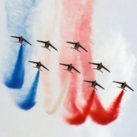
Hello! Herewith my first LSP - for that matter, first build of any sort - in more than 40 years. It represents a warbird rendition (hence the modern VHF aerial on the finished thing) of an aircraft from 12e Escadrille, Forces Armées Bretonnes, in Algeria in support of the French operation there in the 50s. My intention with this bird was to learn and a "what if" subject allowed me to experiment without having to worry about faithfully capturing a real aircraft. That said, I did set myself something to aim at: Did I succeed? Well, I'll let you decide - she's never going to win any prizes but for a first go, I'm happy with the result. When I'm a bit better at all this I might revisit her with a slightly more battered "in service" finish, in European theatre colours. Paint and satin finish are Vallejo, some Xtracrylix used in the cockpit, gloss layer is Alclad Aqua and helped along by brass gun barrels, resin main wheels and various scratch stuff. Markings all masked, the few stencils are HGW wet transfers. Build thread is here . and the only pic of the cockpit I have, currently (I know the armour plate should be black... apparently the owner doesn't ) Cheers! Sepp2 points
-

Academy F18 A / CF-118 A
USMC Herc and one other reacted to TimHepplestone for a topic
Next on the bench will be Academy’s big Hornet.I’ll be building it as the Canadian CF -118 version flown during operation Mobile in Libya 2011. Any advise as to a reasonable load out and has anyone got any experience with the kit? Thanks all2 points -

1/32 Zoukei-Mura Ta152H-0 White 7
Michael931080 and one other reacted to Thunnus for a topic
Thanks guys! Continuing the dry-fit session with the radiator cowling reminded me that the engine will need to be installed since it holds exhaust pipes. I snapped the engine into place to check the cowling fit. The engine assembly does not want to sit correctly on its own without glue. However the top cowling pushes the engine into the correct position. There is a possibility that I can perhaps glue ONE of the two engine side cowlings into place and have the other one removable. We'll just have to see when that time comes. The wing spar has been glued into the wing bottoms. I had to shave the back edge of the spar where it butts up against the PE flaps. I glued the upper flaps onto the upper wings using 2-part epoxy. The roof of the wheel wells have been painted and I've applied the contractor stamp decal from the Eagle Cal decal sheet.2 points -
We all strive for accuracy as best we can but modelling is at heart representational.2 points
-
I have the model ready for the final blend later this evening. I am aware how stark it appears now, but this is part of my "plan". I have begun weathering the belly. Wish me luck.2 points
-
Beautiful work Tim! I agree about the cleanliness... you've got that Grey Matter resin fuselage perfectly integrated with the rest of the kit! I love this view since it shows very cowling bulge so clearly.2 points
-

1/24 scale Rockets, US 5 inch HVAR, WWII and Korean War
Fanes and one other reacted to Model_Monkey for a topic
Model Monkey is happy to announce a set of four 1/24 scale 5-inch HVAR rockets has been added to the catalog. This accurately scaled and detailed set of models represents fully fused 5-inch High Velocity Aircraft Rockets (HVAR) carried by US Army Air Force, US Navy and US Marine Corps aircraft during World War Two and the Korean War. These rockets were also fit to aircraft flown by allied forces including the RAF, RCAF, RAAF, RNZAF and RSAAF, etc. HVAR rockets were typically fit to many USAAF, USN and USMC single-engine fighter aircraft such as the F6F Hellcat, F4U Corsair, P-51 Mustang, P-47 Thunderbolt, the TBF/TBM Avenger, and later the F-80C Shooting Star, F-84E Thunderjet, F9F Panther, and F-86 Sabre. It was also used by some multi-engined aircraft such the PV-1 Ventura and PV-2 Harpoon.2 points -
If it's anything like your SE5a diorama, it will be a beautiful thing to behold!2 points
-
It's not a regardless: most of those panels need to be inscribed, not simply obliterated. We haven't heard a peep from Tan Model so, like Thierry, I fear the 1990s Tamiya kits may be the last word on 1/32 J79-powered Phantoms — although there is talk that Zoukei Mura may do them. Tony2 points
-

Help! Part needed for Airfix 1/24 FW-190 kit
Troy Molitor and one other reacted to chris2962 for a topic
yahoooooo looks brill thanks i have been busy with the rest of the kit i am going to try and put landing flaps on as airfix have not botherd to do any ,it is my first try at doing this as i get inspiration from this forum2 points -
2 points
-
1/24 scale Rockets, US 5 inch HVAR, WWII and Korean War
BiggTim and one other reacted to Model_Monkey for a topic
Actually, despite your and my best research efforts (your AI Mk.IV radar manual find is a huge help), unfortunately, no, there's not yet enough information. We're getting closer, but we're not quite there yet. The awesome radar manual you found provides an amazing amount of very detailed information, especially with respect to electronic characteristics and electrical components. Most importantly for our purposes, the radar manual states in a table exactly how big the enclosure of each major component is. That information is utterly critical in designing a 3D model. Without overall dimensions, I don't know how big to design any of the components (is "Receiver R3066" the size of a deck of cards, a shoebox or the size of a mini-fridge?). The manual you found provides those answers. Perfect. There is still one critical piece of missing information. Where does the equipment go and how is it fixed to the airplane? Sketches in the radar manual only show general placement in the aircraft but don't show precisely how the equipment was mounted. Presently, I am not able to determine the exact position of the equipment on the 3D-printed model or tell the modeler how to install the equipment in their plastic Revell Beau model. Available photos of aircraft under restoration don't show the equipment mounted. That's the quest at present. There are two basic designs I'd like to offer: a radar-equipped station and a non-radar equipped station. Obviously, the equipment for each is very different. So, in order to create a 3D model of each piece of equipment for non-radar aircraft, too, what is needed is a list of the non-radar equipment for the non-radar equipped Mk.X / Mk.21, with overall dimensions for each individual piece of equipment on the list. I don't have that yet. The radar manual gives us good photos of the radar equipment, but doesn't give us any information about the other non-radar equipment of the observer's station, especially for those aircraft that didn't have radar. For non-radar aircraft, more information is needed about applicable non-radar instruments. I have good information about what the "navigation panel" looked like and bezel sizes, but not other equipment off the panel. The Franks book (a superb reference) has some great information but it's not sufficiently detailed to make 3D models of any other instruments or equipment that were present in a typical non-radar Beaufighter. The Franks book does provide a list of major equipment but does not show much about what it looked like. We need photos of any non-radar equipment with at least 2 views, front and side (3 ideally including top) for detailing.* And we need to see how each piece of equipment is mounted so that if there is a mounting like a table or tray or rack, it can be designed in 3D, too. Then there is the 20mm cannon ammo bins and their feed chutes. I know the bins were big and about how big they were, but not with certainty. I know the forward pair were probably slightly different in shape and size than the aft pair because the position of the guns they fed were different. We need better, authoritative, dimensioned 2D drawings of the ammo bins and their feed chutes with better supporting photos.** I know absolutely nothing about the feed chutes. Comparatively, the cockpit is extremely well-documented and research was much, much easier (and faster). Both of the available model cockpits and their associated radios are very accurate because authoritative references were plentiful (if a bit costly). Every so often, a golden nugget of needed information does come to light and I update the design accordingly. We just need more information to complete the design. In the mean time, I'll continue to work on other projects that I hope will delight you. * Photos are needed to help identify details and features. During the design, the 3D model is superimposed over photos and details. Features are then sized and positioned to match the photos. That's how I am presently designing the radar components. It is a slow process, but results in great models. ** I do have some drawings and photos of the bins but those photos and drawings just don't show enough of the bin, especially the feed chute attachment points, to make a 3D model of them. None of my references show how big they were. I do know that some early aircraft such as the early NF Mk.I didn't have bins at all. Their cannons were drum-fed. Spare drums were stored in racks, the observer was expected to reload the cannons in flight by swapping out drums. But I've got nothing on the rack nor the drum.2 points -

1:25 '40 Willys Coupe Gasser
mustang1989 and one other reacted to LSP_K2 for a topic
I did something tonight that I had really dreaded doing, scribing the fender join lines on my Willlys. Once I figured out what to use as a straightedge, it was actually a snap. They still need to be cleaned up, but they are actually very straight right now. I'm a happy guy.2 points -
That's awesome work, Kent! Kev2 points
-

'Flying Circus' - Jasta 11 (Diorama base)
BiggTim and one other reacted to Rick Griewski for a topic
Thanks for the spoke wheel lesson. I need to make wheels for my Fokker DVIII.2 points -

'Flying Circus' - Jasta 11 (Diorama base)
Rick Griewski and one other reacted to BiggTim for a topic
That is actually very similar to the jog I made for my DVII wheels! The only real difference that I didn't sandwich the rim, as it was made from bent and laminated poplar strips. I just drilled the holes through the rim using the jig as a guide, then fished the thread "spokes" through the holes and around the pegs and the paper hub, then glued them in place and trimmed them off just like you did. Because mine were thread, I also stiffened them with a drop of CA. I never thought of doing it for anything at 1/32, but now you've got me wanting to try it!! So very impressed, as usual!! Tim2 points -
Thank you very much! I have taken a few minutes to find the C/G of the model. Actually I'm wrong, I used a previous build G model (now covered in dust on my shelf) "Idaliza" to find the C/G, then I poked a hole in the belly of this beast and super glued a 8-32 nut to the floor of the radio room and threaded a rod to go into it. I was originally (at one time long ago) going to use the bomb bay wall mount assembly to mount the model but it was a few inches away from the C/G. I may have to reinforce the mount as the model is still fairly heavy (even with pieces missing) but the weight should bear down squarely on the shaft and into the planned base I'll be making. While playing around I figured I'd take a minute to mock it all up. The rod will eventually be cut and threaded at each end the big bird, showing her lines2 points
-
'Flying Circus' - Jasta 11 (Diorama base)
D.B. Andrus and one other reacted to kkarlsen for a topic
The German Staff Automobil is finally up on it's 'wheels'. It's been a tough one and a lot of detailing is still needed... Cheers: Kent2 points -
Hi Everyone, Time to put this one to bed. Thanks for putting on the great campaign, LSP! Gaz2 points
-
Pilot and seat installed and fuselage glued together with Tamiya Extra Thin Cement.2 points
-
This time F-5F Kitty Hawk, Kitty Hawk models aren't my favorites. However, the F-5F is a beautiful jet, so I had to have this plane in my collection.2 points
-

1/32 F-14D VF-213 - Finished!
geedubelyer and one other reacted to Marcel111 for a topic
Took some quick IPhone pics of the model before I headed into the mountains. The skunk stripe is on, which is actually very dark blue with a slightly lighter blue border... on the pics it looks about black, as does the real thing. This is how those vents turned out. I used the Scale Navy Stuff parts, which fit perfectly. However, those tore off of the nose section at some point and from there on in it was a huge amount of filling and sanding to get everything together again. I chose to use Archer rivets as fasteners because I did not want to risk pressing rivets into the brittle superglue/filler composite. Not entire accurate since those fasteners are actually flush but I will live with it. Also note GPS receiver. Snapshot of the front section, you can see the skunk stripe blues a little better here. Notice the formation light stips, which I have airbrushed on. I had not noticed that the front one is solid while the rear one is cut into two halves, looks like I will need to correct this... which I am really not keen on doing since with this build it seems every step forward results in half a step back. Cheers, Marcel2 points -
One trick I use is to oil wash the surface first, this outlines the panels or instruments...then all you do is paint to the dark line. Pup by The 3rd Placer, on Flickr Pup by The 3rd Placer, on Flickr Pup by The 3rd Placer, on Flickr Ryan2 points
-
Well, its not the cleanest work.....but for the first time using lead wire, I suppose it's okay. I think that I'll call the engine "done" and move on so I can get the exhaust done and get the front of this bird attached! Comments, suggestions, all are welcome!2 points
-
Little update this time, but still having fun with the EAV-8B Matador ! So, I've started adding the detail to the area under the canopy again - it broke off when I dropped it a few weeks ago - so, here's the start of it. Another point that I'm giving a little detail, is the air intake. When the top doors open, you see some detail on the inside, mostly rivets, so I added some for the top auxiliary doors (the lower ones will be closed, so they don't need them. The inner part of the engine bay, where the LEX joins the fuselage, has been detailed too. First, a very thin piece of plasticard with holes punched in at the right spot glued to the LEX side. After that, I sanded it flush and added a few details to it (which I realise now looking at the photo, you can hardly see...) The connecting box with all the tubing on the port side has been added now. Loads of parts there, but by doing so, the engine bay is almost done. Still have the front part to do, though! Aft fuselage: I've cut out the bad exhaust and inserted a tube that I've sanded flush to the fuselage. Some putty to make sure it is completely flush, but I'm not completely satisfied with the result. I'll have to work on it a little more. At the end of the fuselage, I've opened up one of the exhausts. Next time, I'll have the grills installed. Now it's on to painting the cockpit. When that's done, I'll post some photos of it! Hope you like the progress, little as it is. Nic2 points
-
They are but testing has revealed that smartness varies....1 point
-
HH-60G Pavehawk Kitty Hawk 1/35 DONE!!
Pete Fleischmann reacted to chrish for a topic
Fantastic work....miles out of my league! I’m building snap together by comparison!1 point -
Beautiful work Quang! Cheer's, Jeff.1 point
-
HpH Models comes to plastic !!
Nighthawk Calling 1 reacted to Out2gtcha for a topic
(HINT HINT)1 point -
It's up on Hannants with prices.1 point


.thumb.jpg.cd22b958c9e88a898a21e18b862c523e.jpg)