Leaderboard
Popular Content
Showing content with the highest reputation on 02/04/2020 in all areas
-

KH T-6/Harvard Kicked Up A Notch: Apr 14/20: Finished!
williamj and 11 others reacted to chuck540z3 for a topic
Feb. 4/20 Next step is wing assembly, but before I do that, I want to deal with the lights in the wings. As mentioned above, the port side wing has both a 7” Landing and a 4” red “Passing Light”, while the starboard wing has only the Landing Light. Here’s what it looks like on the left side. Note the 4 screws on the corners of the Landing Light and the black background within the light enclosure. The kit lights are Parts D65 & D66, which are just two depressions in the plastic and the instructions don’t mention that they should be painted. I forgot to take a pic of them before I modified them, so here’s a sprue shot from the ‘net with the parts in the lower left corner. I decided to add some lights of my own, so I thought I would use some model car headlights instead. By my calculations, 7” lights are 5.5 mm and 4” lights are 3 mm. A modeling buddy has the car lights in 4 mm which he was going to let me use, but then he mentioned that they really were not much more than rhinestones, which got me wondering what Amazon might have available? Sure enough, a quick search and I found these: 900 plastic rhinestones in 15 colors, delivered to my door in 24 hours for only $8.99 Cdn. That’s only $0.01 each! The clear and the red ones might work and the rest can be used by my 3 granddaughters as stick-on earrings, so there was no downside if they didn’t work. While I waited for the rhinestones to arrive, I painted the lighting area black and modified the light holders. This is what the rhinestones look like, with clear or colored plastic with a mirror-like finish to the flat side, where there is also a thin adhesive sticker. Note there is also a tiny flaw on each of them, where they were no doubt cut off a sprue of some kind. Unfortunately, 5 mm is way too big, because the lights need to fit within the thick clear plastic light windows. After 2 failed attempts, here is what I finally went with. I filled the two depressions on the light assembly on the left, which is for the right wing, then drilled a shallow depression to hold the rhinestone/light. The assembly on the right was modified as well, with the depression for the red light widened and deepened to accept a 3 mm light and raised slightly, to compensate for wing angle. The mirror finish was sanded off the bottom of each stone, leaving a bit of a dull finish, while the bottom of each rhinestone was painted with chrome paint, as were the depressions, which look a bit rough, but they will be covered. For the light frame, I used airscale instrument bezels which are a bit too big for scale, but I liked them more than other smaller versions I used as prototypes. Artistic license I guess….. Here is one of my earlier attempts with a smaller ring for the light housing. It worked OK, but I wanted something more noticeable. I like this look better. The lens on each light was painted with 2-3 coats of Future/Pledge to bring back the shine. On one set I used Micro Kristal Clear, but I found it to be too thick and lumpy and not as good looking as the Future. Note that the lights were glued at a slight angle, to compensate for the swept back wing angle. With the thick light covers on, however, everything becomes distorted, especially from straight on. The edges of the plastic also refract light like fiber optics, causing a whitish hallo around each cover, which doesn’t look natural. I discovered a fix for this problem many years ago when applying clear canopies to canopy frames, which have the same issue. If you cover each edge with a black Sharpie, light can’t refract inside any more and further, CA and plastic cement mix with the black ink without crazing it as would happen with black paint. I now do this to all of my canopies before gluing them in, which makes the plastic look thinner than it really is. And now some pics of the final product, with more Eduard PE to surround the light housing. Note that the sides of the clear plastic have disappeared with the black ink. From the front, the lights are distorted a bit… But from other angles you can see the light s very well. Putting the wings together, I discovered a few more things. The big gaps on the ends at the bottom should be filled and the navigation lights should be cut off, since there are clear plastic replacements in the instructions, which indicate Parts GP 11 and GP 12. Like many clear plastic parts in my last Kitty Hawk F-5E build, these parts are wrong and should be used in the rudder instead, which calls for GP 9 and GP 10, which show that they have pins to insert into the rudder. GP 11/12 have pins, while GP 9/10 do not. Also, for some strange reason, there is a hole for the pitot tube (Part D38) on BOTH wings, so the hole on the port side wing should be filled as well. Finally, I found a solution to the ribs on the rudder and elevators, where I sanded down the kit plastic and used Archer rivets instead. While the raised rivets look better than before, they are still too high, so should be covered with something. Everything I could think of to use to cover the rivets would be too thick for scale, until it dawned on me: Just sand the rivets down! With the acrylic X-22 sealing in the rivets, they were tough enough to be sanded down about 50% with an 800# grit sanding stick. While they still show up strongly on the bottom after sanding due to strong color contrast, I can hardly feel them with my fingertips, so after a coat or two of paint they should be nice and subtle as they should be. I love experimenting and trying new things, which spices up the build journey. Sometimes I win and sometimes I crash and burn, but when things work out for the better, the whole effort is very rewarding. Next up, the wings, with many changes from the kit instructions as well. Cheers, Chuck12 points -
I wanted to give everyone an update. My daughter's tumor has shrank significantly, more so than the doctors expected. She has finished her induction and next week she starts on consolidation. There isn't much of the tumor left and her primary doctor believes what is left is dying due to the intensity differences. She still has a cyst and there is one spot which appears to be scar tissue. Her brain structure is starting to develop normally, and her ventricles have shrank which means the hydrocephalus is reversing. She isn't out of the woods yet but this is the best news we have had since early September. On another note, since her consolidation is much less involved, this should afford me some bench time over the next few months.10 points
-
Thank you, Brothers. I've been asked to define the wire I'm using for the hydraulic brake lines, main leg bracing/retraction strut, and blue/red tubing for the landing gear legs and engine. The purple wire is beading wire, found at Michaels. I'm sure it can be found at any Craft store. The blue tubing is insulation stripped from copper wire. I don't recall where I got it. It was either from a computer or a tube television. I used the same blue insulation on the first engine detailing project. Here I've used blue and green stripped insulation as wire ties. The brass wire is beading wire, from Michaels, and the retraction wire is monofilament sewing machine thread from a fabric store. This is the same red insulation I used on the first engine detailing project before I redid it with Albion Alloys. I believe I got this insulated wire from Radio Shack years ago. I just strip it off of the wire. This is from the first post on Page 4 of this thread: The brass engine distributor wire is 32 gauge bead wire from Michaels. They have a ton of different gauges and colors. Nothing insulated that I recall. The blue/white insulated copper wire I think I took from a dead analog tv a couple of years ago. The red insulation is from 32 gauge single strand insulated wire, I think from Radio Shack. Otherwise this may do: https://www.omegaeng.cz/pptst_eng/TFIR_CH_CI_CC_CY_AL.html The purple wire for the brake line is 32 or 30 gauge painted wire. I think it may be bead wire also. Thank you for looking and liking. Sincerely, Mark10 points
-

Vietnam Hun "nashville sound" FINISHED
Whitey and 6 others reacted to blackbetty for a topic
some work on the landinggear (AMS wheels, Eduard PE)7 points -
A few extras from Yahu Models7 points
-
Howdy folks, Kevin Williams takes a look at some aftermarket landing gear produced by one of our very own: Synthetic Ordnance Works Main Landing Gear Replacements Thanks, Kevin! And thanks to Synthetic Ordnance Works for the review samples. Kev6 points
-

ICM I-16 Type 24: COMPLETED 3/12/2020
Azgaron and 5 others reacted to Dennis7423 for a topic
Woohoo, update time! When I left you last, I had just started some of the upgrade work in the cockpit. Since then, I have completed some minor upgrades to the kit cockpit, to bring it a little more up to my standards (I'm an accuracy guy, so sue me!) The interwebs were my friend, and I was able to find several photos of restored birds to inspire my work. The colors are my best guess, and especially using some of the more recent restorations that focused on accuracy as well, I felt comfortable using their color recommendations. I attached most of the cockpit into the port fuselage side, as it needed more threading through bulkheads with various equipment. Most of what you see here is kit cockpit enhanced with an Eduard set: 84106078_815853102263937_582761692664954880_n by Dennis SAuter, on Flickr You'll also notice some additional plasticard to the rear. This actually stretches all the way forward to the wing spar bulkhead, which was applied to show the rounded fuselage beneath the cockpit floor, rather than just showing into the wings: 83994928_218537415856486_8885428320489963520_n by Dennis SAuter, on Flickr It's awful messy at the bottom, but that won't matter, as the cockpit floor blocks it. The starboard fuselage side. All those little sections of EZ-Line are to simulate wires to the controls in the cockpit. The I-16 didn't have many creature comforts, and most controls in the cockpit were by way of hand crank, to include raising the landing gear. Each of these "wires" feeds into a pully system on the wing spar bulkhead beneath the instrument panel. ICM fortunately created this piece by way of a block on the bulkhead, so I simply drilled a hole through is and fed each of the lines through it. Now that my hand cramp is gone from using tweezers in such a small space, I am posting this update: 84328663_2790273484344543_3333790298470875136_n by Dennis SAuter, on Flickr Eduard seatbelts round out the cockpit. I used a set designed for the I-153, which are the same shape and size, but a different color. I tell you what, those Russian seatbelts sure are an interesting design. Add to the fact the seat pan isn't connected to the seat back, and that made the chore even more interesting. Pretty pleased with the result though: 84602186_209124350264522_7627909540293378048_n by Dennis SAuter, on Flickr With all that done, it was time to seal up the fuselage halves: 84510721_474334313240461_4960453503349686272_n by Dennis SAuter, on Flickr Wings are in place simply to hold the fuselage into the right shape while the glue dries: 84270242_203724504086791_4759564946474270720_n by Dennis SAuter, on Flickr If you look closely, you can see the "wires" threaded through the pulley system on the floor: 84017949_776800949480387_511468628575518720_n by Dennis SAuter, on Flickr And from the front, pulley to the lower left: 84116042_624248465061344_7446932700910321664_n by Dennis SAuter, on Flickr That's all for today folks! The rest of this build should fly by, and the seams are small. The engine is already built and painted, and once I get the cowling done on the inside, I can get that installed. The wife is out of town this weekend, so I should be able to enjoy a whole lot of bench time! As always, comments and critiques are most welcome. Thanks for tuning in. - Dennis S. Thornton, CO USA6 points -

Tamiya 1/32 F4U-1 Birdcage Corsair - Done!
Starfighter and 5 others reacted to Brett M for a topic
Thanks Mike, Lothar, I appreciate the comments. Quick post tonight, just sharing some engine progress. I've painted the prop governor, distributor, magnetos etc. (not sure actual names) and just need to attach them later. I've drilled the spark plug holes for all the wiring to be run to them and will be starting on wiring the ignition ring next. PS, I hate close up shots......things to fix! Glad this engine is much smaller than the image is!6 points -
Lots, but I won't get into it for fear it leads into a Trump bashing thread which wasn't my intent. Ron6 points
-
Little Marauder update: Over the weekend, I made some more clear vacuformed parts for the nose, turret and tail. The nose must be redone as I wasn't careful enough when romoving from the mould, so what you see is just for a quick demonstration: It all still need some clean-up, but overall the plan seems to work out. I enlarged the opening in the fuselage for the turret since I have the impression the turret is too small on the plan from the Warpaint book. Somewhere I read that the turret diameter is 41 inch. Talking about the turret, the obvious question arises: what color for the turret? On some pictures they are some kind of interior green: https://c1.staticflickr.com/5/4908/44189918460_86a363267c.jpg That's the turret from Flak Bait: https://thumbs-media.smithsonianmag.com/filer/86/6f/866f22ba-be2d-49fa-b846-9b78c6983c8a/4.jpg__1072x0_q85_upscale.jpg Here, the turret seems to be metal/aluminium: https://c2.staticflickr.com/6/5099/5521447033_6b3d731ef3_b.jpg Here not: https://i.ytimg.com/vi/HG_DQC1deB0/maxresdefault.jpg Here on the production line, they are black/dark grey: http://320thbg.org/martin_marauder/domes_destruction.jpg At the moment, I tend to black/dark grey for my model, but any additional information would be welcome. Cheers Alex.6 points
-
well good evening everyone it's been a while, but having got Xmas, a vacation in Thailand and a shoulder injury out of the way, I finally got back to the bench... so where were we... Tailwheel... for some reason I have been putting this off, but it is finally time to make myself do it. I expect it's because it's a complex bunch of assemblies - predominately this one - this is the main bracket the tailwheel fork goes into - here nicely rendered by someone in 3D (I did try that, but it would have taken less time to make it ).. ..there are no drawings of the fork actually holding the wheel, but there are these for this assembly so I scaled them and coloured the main features to help me start a replica.. ..I started with the two spigot parts from bits of tube and the 'Y' shaped bit in plastic card.. ..this was then assembled and P40 filler added to block it out a bit.. ..some shaping .. ..and a coat of primer - it's a long way from being right, but it's a start... ..also Tim Perry kindly prined the 3D wheel design I did.. ..in other news, the model has a name now - I painted the nose art using a mask Radu Brinzan prepped for me.. .and Don Lopez's name & kill markings added under the windshield.. ..and the fuselage stars n bars - this is the second attempt after the first peeled while unmasking.. ..it is getting harder to work with on my increasingly messy bench... ..hope everyone is well TTFN Peter6 points
-
Well it’s been quite some time since I sat at the bench working on the Raiden, the new knee distracted me and the exercise regime took up a lot of time (still does) and then all the summer jobs came along and my modelling mojo left me. However the build up to Telford started me getting interested again, then Telford itself and the aftermath got me back in the saddle. So I have been quietly working on the Raiden again, it was a bit difficult at first to pick up where I was up to and what I had planned to do but progress so far has been good. The first thing to do was complete the RB products seat belts, this was a bit of a rough re introduction to the build as they are a bit fiddley, but eventually they were completed. I don’t like just dabbing some CA on and plonking the seat belts on the seat so I drilled some holes in the seat and inserted some plastic rod to attach the belts to and away we went. Then it was a simple matter of assembling the cockpit components that I had already painted, this went very well and everything fitted nicely. More soon Cheers Dennis5 points
-
Yak 3, the Special Hobby Hi-Tech Kit
MikeMaben and 4 others reacted to Dpgsbody55 for a topic
Here's a few more shots of this plane, this time without my untidy desk as a background . Plus, I couldn't put them in the previous post, for some unknown reason. So that's it for this build and on to the next one, which will also be a Russian front plane for this group build. Cheers, Michael5 points -
Yak 3, the Special Hobby Hi-Tech Kit
Azgaron and 4 others reacted to Dpgsbody55 for a topic
I'm calling this done. With the exception of one of the brake lines (why is it always the second one that gives you more trouble??), it all went together quickly. I kept the weathering to a minimum as all the pictures I have show mostly clean and well maintained aircraft. Here's the underneath, with the undercarriage complete and a few stains added behind the engine cowling, oil cooler outlets and radiator. Most of the plane is wood, and paint doesn't scratch as it does with metal. Next are some interior shots. One thing I almost completely forgot is the guns on top of the engine. I even tidied up my desk and threw out all the junk from the build, took some photos, then realised what I'd fogotten. So I quickly made two from brass tube, which is what I was going to do anyway as it looks so much better than plastic. Now that it's all done, I'm very pleased with the results and will consider another one, some day. Glad I have plenty of decals for that A couple of observations about the kit, however. Firstly, I wish CMK or someone would do an engine to go inside this. After all, SH have cast the top cowling as a separate peice, so perhaps that's on the cards. Secondly, could you please number the parts on the sprue, please, Mr Special Hobby?? It's very frustrating having to constantly flick through the instructions to identify parts. Here's my solution; still annoying, but less flicking back and forth. Back to the kit. The plane I modeled was flown by Lieutenant Savelly Nosov, Hero of the Soviet Union, who in 139 flights, shot down 16 enemy planes and shared in the destruction of 3 more. He was part of the "Sword" ace fighter group (3rd FAC), and their emblem is painted on the nose. They often painted the nose of their planes in red, for quick recognition. This plane operated on the Belorussian front in the spring of 1945, ending the war in Austria. I'd like to thank everyone for their support and kind words in this build. It's always encouraging to get feedback on these build. Cheers, Michael5 points -
Hi folks, Here are some photos of my progress on the Abrams Loader's Armored Gun Station. Loader's Hatch interior view. The wing nut are functional and the Periscope insert is removable and the Periscope Housing rotates 360 degrees. The M240 Gun Cradle and Shield Armored Surround Loader's Thermal Weapon Sight As finished as possible until after paint TAFN, Thanks for looking in! Barry5 points
-

F-117A • Nighthawk
blackbetty and 3 others reacted to F`s are my favs for a topic
oooh, it went just beautifully I'm very happy right now. The merging of the canopy and the frame went perfectly... I don't know how much it is visible from these pix, but enjoy!4 points -
Moving right along, I have a part of the engine case in work - a lathe machined acrylic part. Here is the section I am modeling (between the vertical red lines): So the part has nine mounting surfaces for the aft row of cylinders, which comprise the forward portion of the part. And it also has 18 faces on the aft portion of the part - nine for the intake pipes, and nine for the motor mounts (only six of the nine will be used for motor mounts). You can see part of a motor mount above, between two of the intake pipes. I made the part out of 1.625 inch diameter round acrylic stock. Here are a couple of shots showing progress on the mini-lathe: It's messy business with acrylic shavings flying all over the place. The machining was tricky, but do-able. Here is the finished lathe part: Then I converted the machine into an end mill, using a cutter, and faced off the flats for cylinders, motor mounts, and intake pipes: A sneak preview with a completed cylinder, and a Lord motor mount: Some of you may remember similar work on the P-47 engine a couple years ago. This one is going to be better. Next up is hole drilling on this little jewel - holes for the cylinders (qty 9), holes for the valve guides (qty 18), and holes for the intake pipes (qty 9). And then it will gather dust as I continue cylinder work. I'll show y'all the finished part in a few days probably. OK - the next few weeks will be finishing off the front row cylinder heads. Not alot of fun, but I will be happy to get it behind me. Don't go away!4 points
-
FW 190A-3 Camouflage color
pvanroy and 3 others reacted to Tolga ULGUR for a topic
On the other hand, I have started this project for a while.4 points -
IBG Models - 1:32 PZL P.11c Test Build
Tnarg and 3 others reacted to R Palimaka for a topic
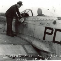
The whole kit looks superb, with incredible attention to detail. I am so excited about his one. Even the corrugations on the wing look to be in scale. On the real thing they are quite petite, and seen at an angle from the side almost disappear. These are photos I took in August 2018: Richard4 points -
XB-51 Dragon
themongoose and 3 others reacted to Dandiego for a topic
Cockpit painting mostly done. Just a few details left. Here you can see how effective my jigsaw panel technique looks. No it is not accurate but will look the part when looking through the small canopy. Notice the "equipment " in the rear cockpit. Both seats. The crappy looking one will be buried in the almost impossible to see rear "pit". Generic panels to busy up the rear crew position. Dan4 points -
Yak 3, the Special Hobby Hi-Tech Kit
Azgaron and 3 others reacted to Dpgsbody55 for a topic
Thank you, LSP_Ray and Maru5137. Aside from the MiG 3 I did a couple of years ago, and that one was white, this is the first I've built of a Russian camouflaged plane. I'm enjoying building something different, and it's great to see these planes come onto the market. Well done, Special Hobby and ICM in particular. A small amount of progress, but it's taken some time. And been fiddly. The wheel well bays got some detailing, and the undercarriage is now on. The kit provides some rib parts which add to the detail in these bays, and I've also added a bit of Eduard photo etch hydraulic lines. Next up was to add the main wheel legs and the two actuator/linkage parts. Getting all three in at the same time proved impossible, so I glued in the legs and the linkages first, then the hydraulic actuators. Before that, however, I added a length of 0.5mm stock rod to the top of the main legs to provide some extra glue contact with the wheel well roof. The legs glue onto the back wall of the wheel well bay, not the upper wing. In test fitting, it appeared to me that a gap would exist between the top of the leg and the top of the well, so the 0.5mm rod took up that gap and provides a little extra strength. This little mod isn't visible once it's all in place. The undercarriage legs and linkage went in first, and need to go in together as the linkage attages to a point on each leg. Once dry, I added the hydraulic actuator and hooked up a hydraulic line to that actuator. I waited 24 hours for the legs to dry before adding the main wheels and tail wheel, but I couldn't resist taking a shot of the plane in the "pre wheel" state. While I was waiting for the legs to dry thoroughly, I added some clear nav lights to the wing tips. The kit has these moulded on, to be painted, but they also supply clear parts. So I filed out the wing tip and added the clear bits, then painted them. Much better . Lastly, I've added the main wheels and the lower undercarriage doors, together with the tail wheel. The main wheels were another fiddly job as one side goes onto the stub axle on the leg, and the other needs to go into a pin on the lower doors, which also attack to the legs at a particular point. I'm using the resin wheels so they had to be CA glued, and the plastic bits styrene glued, and the wheels quickly lined up as they're "weighted" to represent the weight of the plane. So first I put the tail wheel leg only into the plane, then with three hands to hold the model, hold the wheel and hold the lower door, I quickly set each piece in place and lined up the flat parts of the tires. Fun, fun.... Next up is to add brake lines, touch ups, upper doors and inner well doors, then put the prop back on and a little more weathering and it should be finished. Then on to the next model . Hopefully that will all be done this week. Cheers, Michael4 points -

Tamiya 1/32 F4U-1 Birdcage Corsair - Done!
Starfighter and 3 others reacted to Brett M for a topic
Thanks Jep! Painting, painting, and more painting...….walkways are on, single digit 1 on the fuselage for "Reluctant Dragon". Anyone know how thin Montex decals area? They look pretty decent, but I've never used them.....hoping I can hide the carrier film well. Also, the white stripes that I see on the wings of some F4U's, do those mean anything? No clue if this bird had them, but they do add interest...... Dropped the flaps in place as well for some photos. I'll finish the walk ways on those tomorrow. Just another quick update tonight.....back to the wifey, migraine night for her. And.....color hue change, don't ask me why I didn't fix it.....4 points -
Well just for change I'm doing (another) Silver Wings Fw44 Stieglitz! This one I'm very happy to say is a commission build for the lucky chap who owns and flies this beauty: It took Richard 5 years to restore this one, and he's actually restoring another original Luftwaffe one right now, but the model will be depicted as D-EMNN. We will be using the swastika on the model rather than the Focke-Wulf logo on the plane. Having recently completed one Stieglitz I'm thinking about bits I struggled with, techniques used and order of assembly to make this one an easier (read trouble-free) build. I bought 50% of Hannant's stock to make sure I had one!3 points
-
Other Nurmberg LSP notables...
Alain Gadbois and 2 others reacted to dutik for a topic
More stuff: Buchon conversion for Hasegawa Bf-109:: Available since some weeks, but it looks so nice: Kitty Hawks "Pave Hawk": Not LSPs, but cute! Indeed: You know the Gladiator, P-51, A-26B from other threads, so here no images of them. Enjoy - dutik3 points -
Other Nurmberg LSP notables...
Troy Molitor and 2 others reacted to dutik for a topic
There is a lot more of LSP stuff: Wingnut Wings Lancaster testshot: HP 0/100: Fokker DR.1 Also a late one, in another boxing of the kit. WNW announced a new kit: A Hansa-Brandenburg D.1 "Star Strutter" One more variant of Miniarts Autogyro: Enjoy! - dutik3 points -
New Landing Gear Products
LSP_K2 and 2 others reacted to D.B. Andrus for a topic
Hi Bill Yes, it's taken a while, had a 1:1 scale project pop up and put this work off schedule. However, will be ready to the first Shinden test mold this week. Had to modify the nose gear so the wheel can be attached, but it should work out well. The black plastic is a strange, soft material, I hope Z-M gets away from that stuff in their kits. The Ki-84, TBF/M and SBD legs are on the work bench, too. Cheers, D.B.3 points -
Fw190 V21 prototype
Anthony in NZ and 2 others reacted to Alain Gadbois for a topic
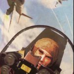
Hi all! The V 21 is a prototype and similar Fw 190 had additional instrumentation. I do not have a picture of the cockpit of this aircraft, but of two others. I have copied one for this project. There is a small panel added where the gunsight should be and another below the instrument panel. There will be a total of seven instruments I have to add there and additionally I have started drilling out the kit instruments to replace with decals (a couple are drilled on the kit part). A unique characteristic of the V20 and V21 is the shape of the opening for the wheel wells. In short, the rear of the opening is straight compared to the standard Fw. The doors are thin styrene sheet that will be delicately shaped to fit the wing and lower fuselage contours. At this point, the lower engine cowl had been filled and sanded to a close to final finish and the central cover between the wheels had the guns ports and the depression filled. The part was primed in dark grey. I tried to assemble all these elements, and noticed a break in the fuselage profile at the joint between front cowl and the central panel. The photo of the V21 (and normal D-9s) shows no break so there is something wrong here... I added styrene strips and filled again to get the correct shape. While this is going on, I adapted the cut out D-9 kit rudder to the ZM Ta 152 tail. The reason is to keep the pattern of the fabric surfaces uniform on the kit. Very good match in elevation but I had to add some styrene to widen the base. I also kept the D-9 tailplanes for the same reason. The fit is also good and I bent up the moving surfaces to create a bit of interest. Note: do not forget to pull the stick back in the cockpit! Thanks for watching! Alain3 points -
Tamiya 1/32 F4U-1 Birdcage Corsair - Done!
Anthony in NZ and 2 others reacted to Woody V for a topic
Yea, you need to start all over again. But I'll take that one off your hands if you're just going to toss it.3 points -
Not sure what you're worried about, Brett - engine looks great! Kev3 points
-
Well, here it is: With regards, Rob3 points
-
That's a Canadian for ya. I was serious though. I think the basic shapes are correct.3 points
-
3 points
-
Thanks for the replies guys, much appreciated. Nice pickup. Whilst researching the build, I decided to go with the green that I used based upon the photo below. As I am using a dark brown wash over the panel lines, the area that I have painted the name has become tinted and appears a bit more olive than in the harsh light that I use when the photo was taken.3 points
-

F-100D Thunderbirds SIX Foiled Again - Finished!
Gazzas and 2 others reacted to themongoose for a topic
Thanks so much guys for the comments and support! For those of you familiar with American football here’s 4 quarters (no halftime) of work lol I used the kit part to roll the slight curve into it. I’m sure glad Eduard has pdf’s for these or it would have been harder for sure. Blowing up the images is almost a requirement, especially on the older instructions without color as it’s hard to tell where pieces go.3 points -
MiG-29UBS Tiger Camo available in 32nd
BloorwestSiR and 2 others reacted to Out2gtcha for a topic
I like it! Having recently acquired the new UB kit, I might have to invest in a set of these3 points -

Our Hobby needs a nice P-38
Phartycr0c and 2 others reacted to LSP_K2 for a topic
The Trumpeter kit is not really all that bad, but a new kit from the likes of Tamiya or equivalent, would indeed be awesome.3 points -
Little update this time, but still having fun with the EAV-8B Matador ! So, I've started adding the detail to the area under the canopy again - it broke off when I dropped it a few weeks ago - so, here's the start of it. Another point that I'm giving a little detail, is the air intake. When the top doors open, you see some detail on the inside, mostly rivets, so I added some for the top auxiliary doors (the lower ones will be closed, so they don't need them. The inner part of the engine bay, where the LEX joins the fuselage, has been detailed too. First, a very thin piece of plasticard with holes punched in at the right spot glued to the LEX side. After that, I sanded it flush and added a few details to it (which I realise now looking at the photo, you can hardly see...) The connecting box with all the tubing on the port side has been added now. Loads of parts there, but by doing so, the engine bay is almost done. Still have the front part to do, though! Aft fuselage: I've cut out the bad exhaust and inserted a tube that I've sanded flush to the fuselage. Some putty to make sure it is completely flush, but I'm not completely satisfied with the result. I'll have to work on it a little more. At the end of the fuselage, I've opened up one of the exhausts. Next time, I'll have the grills installed. Now it's on to painting the cockpit. When that's done, I'll post some photos of it! Hope you like the progress, little as it is. Nic3 points
-
a few hours of grinding and scraping to thin the plastic (on the left wing halves) and then punched drilled and broke the wing to get this the outsides of the wing halves, I will add some structure inside the wings as they can now be seen through.3 points
-
Some more pics from Ron His explanation for the first one is as below. `Carrying 2 napalm cans inboard WAS used operationally, but as I pointed out, it made the a/c very heavy and sluggish. Most often we carried MK82 500 pound bombs on the inboard TERs. I can recall a few times when the runway temperature was critical in whether or not they would let us takeoff with such a heavy load. We sometimes sat idling for 15 -20 minutes waiting for a one degree drop in the temperature so we could roll - and then, who knew if we had enough runway or not? If the afterburner blew out, it would have been all over. As you know, it was rather hot and humid in Vietnam.' Some more work. I asked Ron if he had his name on the side of the aircraft. He told me over a couple of emails the following: The color schemes varied. Sometimes dark olive background with white letters. Other times, blue background and white letters. In my memory, I believe that 197 had the solid dark olive background with white letters. The name was as follows: CAPT RON SWANSON. That would have been placed just below the front windscreen on the fuselage. It didn't have pilot on it, although some did. With regard to the issue of the name plate being on both sides of the a/c, more often the name of the crew chief appeared on the right side of the cockpit. As I recall, there was no name plate on the right side of the cockpit of 197. After a bit of research, I settled on my best guess as to what this would have looked like. There were many different variations on the name plate, both in position and size, as well as text. I had to balance these items with the limits of my mask cutter. After many attempts, this is what I came up with. The model is really starting to come together. Enjoying this build alot.3 points
-
Thanks for the comments guys. some more work. I asked Ron about the configuration of the ordnance. Some photos show Napalm on the outer pylons, some show them on the inners. Likewise for the bombs. Here is what he had to say. ‘One of the photos shows a typical load, (and the one used on the mission we have spoken about) with 2 Mk82 high drag bombs on the outboard stations, and 2 Napalm cans on the inboard stations. Second photo shows me just before a combat mission in late 1968. Third photo is unusual. In late 1968 our squadron (615th TFS) was made experimental. We were to try out what was called Triple Ejector Racks (TER). Instead of a single weapon on the inboard pylons, this new rack could carry 3 bombs. Couldn't carry 3 napalm cans because that would make the aircraft too heavy and the cans were to "fat" to fit on the racks. Thought you might like to see this configuration.’ Here are the pics. And here is the excellent pic of Ron about to depart on a combat mission. As the bombs were to go on the outer pylons, my references showed that they were different to the kit pylons. There are protrusions each side of the pylon which form more beefed up sway braces, so these were scratch built from thick plastic card and sanded to shape. I then used brass rod and disks of plastic card to make up each individual brace. The bombs have had brass rod inserted into them to attach them very firmly to each pylon. Basic colours. I will weather and detail these a lot more than this. Many of my period reference pics of combat jets show them with numerous lift point symbols. These decals were not present in both the kit or the aftermarket Cam Pro stencil data sheet. I made up a mask with my mask cutter and sprayed them on. Forward fuselage. There is one on the rear of the canopy as well. Rear fuselage. I was able to find a pic with two lift point symbols on the horizontal stabilisers but was unable to find anything for the wings, if they were there. Any help would be appreciated. How the model sits on my workbench. Still lots to do but certainly getting there. Noticeable is the armament panel decal, once again not in either decal sheets. I found one in the AoA set for the Cessna O-2.3 points
-
Howdy folks, Andrew Birnie takes a look at Aerocraft's night fighter conversion for Airfix's big Hellcat: Aerocraft 1/24 Hellcat F6F-5N (Early 5) Night Fighter Conversion VF(N)-41 White 13 Thanks, Andy! And thanks to Aerocraft Models for the review sample. Kev2 points
-
Tamiya 1/32 F-15 single seaters
LSP_K2 and one other reacted to thierry laurent for a topic
Well regarding the exhausts nothing can beat the KA models 3D printed sets!2 points -
MiG-29UBS Tiger Camo available in 32nd
Out2gtcha and one other reacted to BloorwestSiR for a topic
I've already got these masks and they're very nicely done. Carl2 points -
What Kev said, I've stared at the pic for at least 5 minutes without noticing any shortcomings - except that your engine looks by far better than any of my attemtps would. Lothar2 points
-
Trumpeter 1/32 MiG 29A,C,UB and Su27/30 questions.
chrish and one other reacted to Stokey Pete for a topic
As far as the Flanker is concerned, it depends entirely on how you approach your modelling. If you're happy to overlook a few obvious inaccuracies, you can build a perfectly good looking and acceptable version from the box. If you want hyper accurate and perfection, be prepared to throw a whole heap of money towards Zactomodels, Aires, Eduard, LindenHill, etc. Add a whole heap of scratchbuilding to that and you'll get the accuracy. I learned the expensive way that accurate doesn't always mean a satisfying result at the end. I've more recently had more enjoyment from simply building a kit rather than worrying about its flaws.2 points -
Another Goldfinch!!
Phartycr0c and one other reacted to mozart for a topic
Should be fun to paint Brian! I’m hoping a “fact-finding” flight might form part of the deal!2 points -
I found my Dads old Navy Slides (CVA-66 USS America world Cruise 1968)
Lothar and one other reacted to Oldbaldguy for a topic
The last photo you posted of the Shellback ceremony ( I have my dad's certificate from when he joined the Loyal Order of Shellbacks many, many years ago on the Midway, BTW) shows a couple of RA-5Cs in the background. Heavy Thirteen was the deployed Viggie squadron on this cruise, but there, in plain view, is a Viggie from RVAH-5 parked on deck among the airplanes from Heavy 13. This is the kind of thing that makes modelers and historians nuts because, to the uninitiated, it can't be. The simple truth is that Naval Aviation has always been an evolving thing in which there are no absolutes, so almost anything is possible. When the RA-5C first hit the fleet, squadrons were equipped with six airplanes but Vigilantes were big, complex and complicated. Maintenance requirements alone put a big dent in the number of airworthy airplanes available in a squadron at any one time. Then the attrition rate from accidents and combat losses during Vietnam quickly decimated the number of airplanes available to equip the ten squadrons that flew them. So cross-decking from one squadron to another became more and more common as the fleet got smaller. Even when I was a teenager doing stupid teenager things, nothing got my dad's nose out of joint more than being forced to trade a real POS Viggie from another squadron for one he'd sweated blood over working off page after page of squawks only to have it come back later (if it ever did) a POS. That's likely what happened in this photo. Heavy 13 needed a minimum of X airplanes to meet mission requirements and had to borrow an airplane from another squadron to get the job done, in this case it came from Heavy Five. Remember the boarded and shuttered #606 in your earlier photos? That one likely was the culprit; it was just too broke to fix on a cruise so they brought in a replacement. Or maybe they lost one of their planes at sea -- stuff happens in carrier aviation. Of course, there may be a completely different and more plausible solution to this mystery, but that's my story and I'm sticking to it. Cheers The Old Bald Guy2 points -
An early recon bird in the Haze scheme, is on my bucket list.2 points
-
Jay, these are extraordinary... A quite incredible amount of work for which you can rest assured you are making THE most accurate 1/18 cylinders in the world today bravo Peter2 points
-
Have been busy with some of the smaller stuff on the kit. Necessary to get the kit a little better, but quite time consuming. First, correct a mistake made in the kit. On the port side of the upper fuselage, the in-flight refuelling probe is located. To make sure that you know where to glue it, Trumpeter provides some panel lines to guide you. The problem is, they put these lines on both sides! Oops. So, on the starboard side, the lines have to be filled with putty. I've also finished the trailing edge flaps, engraved and riveted them. The nozzles of the kit need some attention. The halves and the vanes inside need to be cleaned-up and some details needs to be added. Some putty is required here to get everything smooth. For the Spanish Harriers, these nozzles have to be painted in the fuselage colour. Some more work on the cockpit: the seat with the two rings in front (one ejection ring and a smaller green one next to it) and the leg straps and the instrument cover with the HUD, additional instruments and documents clip to the side. The canopy framing; since the last post, I dropped it - smart, I know - and the wiring on top of it cracked off. I'll have to redo all of that. I scratched the aft part of the canopy frame because this is all missing in the kit. You won't be able to see much of it, but just enough to see that it's more like the real jet. Here's the status of the cockpit. The fuselage halves aren't glued yet. Still need to add some more details, but painting the cockpit is getting closer! Final photo for now: the starboard side of the upper wing interior is almost done. The part with the yellow and metal tubing is just 5 mm long and holds just over 30 parts. On the port side, this has to be added as well. Well, that's it for the update! Hope to be back soon! Nic2 points

