Leaderboard

Popular Content
Showing content with the highest reputation on 03/21/2019 in all areas
-

1/32 Kitty Hawk F-5E Kicked Up A Notch. Oct 3/19. Finished!
jgrease and 12 others reacted to chuck540z3 for a topic
From the sides, however, the front panel lines are lower than the rear on both sides… While the bottom fit is quite bad. This may have been created by the insertion of my plastic pipe intakes, but I don’t think so, because the fit was not forced. In any case, sanding all this down while retaining the fine detail will be very tough. After a LOT of sanding and rescribing, I think I have the join licked. Again, ghost panel line detail can still be seen under clear CA glue filler. As expected, this bottom join was a bear to fill and re-scribe, but it turned out pretty good after all. With that out of the way, it was time to attend to the front intake parts. As you can see, there are 6 moon crater pin marks on each side and a lip at the rear. The curved cutout may be there so that you can see the engine fans from the front of the intake, although with nothing but plastic junk inside, why bother? That rear lip, I assume, may be for future or failed intake parts, that never made it in the current kit? The pin marks were filled with CA glue and sanded smooth, while the rear of the intake was filled with sheet styrene, to smooth out the intake and create a thicker join to my pipe intakes. A view from the rear, showing how the styrene parts are interlocking, much like the rest of the intake parts. My plan is to not paint the white styrene, but paint the forward portion gloss black as found on my subject. That way your eye will see a sharp demarcation from black to white, with nothing but white found behind in the plastic pipes. To get a good and smooth paint finish, I am going to paint the intakes before assembly both front and back. I will also paint the sides of the fuselage where the intakes attach, again for the same reason. This needle-like jet is now really looking a bit menacing and mean. I love it! Cheers, Chuck13 points -
Pre-shading. It needs to be fairly stark as the top colours are going to be dark. I’ll be using MRP paints for the colours and they are very nice at gradually building up the opacity so it hopefully looks just right... Guy11 points
-

HPH Models 1/32 C-47 'That's All Brother'
Dany Boy and 5 others reacted to Crossofiron for a topic
Hello all, I must confess to being a bit of a HPH Models Groupie. Iv'e got five of their kits and pre-ordered this few months back; It is simply stunning!!! It cements, in my opinion, why HPH are the best model 'artists' in the world... It's up there with the PBY which is my next project; I simply had to have a go at this one first! Here's what you get when you take off the sleeve and open the box; Here's a sneak preview of the size; I of course, had to purchase the Landing Flaps which are sold separately; Now, to the subject (which I have the support from HPH Models for); I am going to get unique decals produced for this project and will update you on what I did of course. From the that's all brother.org website; Nearly 75 years ago, on June 6, 1944, That’s All, Brother carried the first of the paratroopers from the 101st and 82nd Airborne divisions. Piloted by Lt. Col John Donalson, the plane led over 800 C-47s that dropped over 13,000 paratroopers into a battle that changed the course of mankind. After serving on D-Day, and in Operations Market Garden, Repulse, and Varsity, the airplane returned to the United States and was sold to the civilian market in 1945. During the course of many owners over the next several decades, the historical significance of the airplane was lost and it was eventually sold to be scrapped. Fortunately, two historians from the United States Air Force discovered that this historic airplane was lying in a boneyard in Wisconsin. The Commemorative Air Force was able to acquire the airplane, and through a large group of donors and volunteers, restore the airplane to flying status. So all, there you have it, now to get all the stuff out and get going!!! Thanks for looking. Cheers Steve6 points -
OK - pretty big update: Both LG doors are done and installed, the wings have been glued to the fuselage, the wheels are permanently fixed to the axles and held on with the axle caps. And, the centerline bomb shackle and sway braces are installed. Take a look at some pictures: First, here are some real live sway braces from Dottie Mae, along with the defining engineering drawing: And my version: They were not the easiest of projects what with the complex (and really small) shape. Here is the bomb shackle: Now the belly of the aircraft looks like this: Addition of all these underwing parts have added much needed completeness to the look of the model: Note the axle caps - I made them a couple years ago! Finally they are installed!! OK enough enough (got carried away). Not done yet! This aircraft will soon receive the wing mounted bomb pylons which are going to be rather involved. Like usual I will take you through it blow by blow. And let's not forget about the pitot mast - last because it is fragile and gets in the way. Next post you will see that, and the wing decals. Then I will need to transfer over to ready for inspection. How does one do that?6 points
-
 Regarding the new 1/32 scale Beaufighter cockpit, the model should be ready by the weekend. The last bit of research is to confirm the radio location and radio rack configurations for typical Mk.I, Mk.VI and Mk.X aircraft. Otherwise, the last cockpit features have been designed. Here are left- and right-side canopy sill instruments. These features are to be fixed to the interior of the Revell kit's fuselage sides. They are depicted in the renderings below in their approximate positions in relation to the other cockpit parts. The next project nearing completion is an upper cowling with accurate shape and profile for the classic Airfix 1/24 scale P-51D kit. The upper cowling of the otherwise excellent Airfix kit is noticeably not as "full" on top, forward, as it ought to be. The 3D design is based on high resolution scans of original North American Aviation blueprints. Photos of the first test print are below. And now for the 1/24 scale P-51D upper cowling for Airfix kits:5 points
 -
1/32 Kitty Hawk F-5E Kicked Up A Notch. Oct 3/19. Finished!
jgrease and 4 others reacted to chuck540z3 for a topic
March 20/19 Back again after a few weeks on a cruise to Hawaii and back, where my wife and I were able to meet Scott Wilson and his wife, who helped me so much on my long F-4E build. As mentioned in my first post, Scott sent me the 1/32 Hasegawa version of the F-5E and the now very coveted Black Box cockpit, which has been instrumental in “kicking up a notch” the cockpit of this Kitty Hawk kit instead. Scott and his wife Lei took us on a full tour of Volcano National Park on the Big Island and we learned many things about the recent volcanic eruptions and how they affected his community. Scott now flies an air ambulance in a Beechcraft King Air, so he has hundreds of photos of the eruptions from the air that he shared with us. Very cool- as was our all day island tour. I hope to return the favor if he and Lei ever make it to my neck of the woods in Calgary/Banff, so thanks again Scott! Obviously, I haven’t had much time for modeling lately, but I did manage to get the main fuselage assembled this week, complete with my hack seamless intakes made out of PVC plastic pipe. Since the pipe is so thick and hard to sand, my plan is to create a bit of an optical illusion within the intakes, so that all you see at the join with the front portion of the intakes is white and if you’re lucky with a flashlight, the front of the engine fan. After heating and bending the plastic pipe to fit, I cemented it in with lots of thick CA glue, much as I did the resin cockpit. To fill the remaining gaps, I used good old Poly Instafill, primarily used to fill cracks in drywall. This worked really well, because the filler dried quickly, was easy to sand smooth and more importantly, I didn’t have to paint it white. Although really hard to photograph, here’s what the intakes look like inside and if you squint, you can see the front fans. These pics also show the challenge of creating seamless intakes for this kit, because they must flex up and over the landing gear wells. While the prototype Phase Hanger Resin intakes appear to do this, an email exchange with Gary of GT Resin indicates that he may try to incorporate the gear wells in his F-5 intakes as kit replacements to reduce this arch, much like his F-15 seamless intakes that I used on my Aggressor last year. In any event, any new seamless intakes will be better than my plastic pipes and, in the meantime, until they actually become available, plastic pipes are better than nothing! Elsewhere, the fit of the top fuselage to the bottom half was quite bad in many areas and not so bad in others. The panel line and rivet detail isn’t bad, but using several references I did make some changes. The seam line from the rear to the horizontal stab pin is real and should be retained, but forward of that it should be filled completely, as shown in purple below. Other vertical panel lines should be deleted, also in purple, while adding the two blue panel lines instead. And here’s the same pic without all those colored lines for reference. Unfortunately, the dark wash I used earlier can still be found in “ghost panel lines” that I have filled with clear CA glue. For the rear, I used both kit and Eduard PE parts. For some reason only the left of the 4 holes at the top is open, which I found in many different reference pics. This hole was drilled out, along with the loop in the middle from the top. FYI, the wing will cover most of the seam line along the front, so repairs to this area are mostly unnecessary. Before attaching the front intake parts, the front and rear fuselage halves should be cemented together into one unit. This join is poor and weak, so I used the old styrene strip trick to reinforce the junction, fusing the two parts together solidly. From the top, the panel lines line up fairly well, albeit a bit lumpy and no, this join line should not be there as a panel line, as I’ve seen with a few builds of this kit.5 points -
Close examination of photos revealed a small change was required on the underside of the fuselage. Italeri had the same layout of panels on both sides of the fuselage whereas the photo of the RAAF aircraft showed a very different story. Here is the panel in question, a double up of what it looks like on the other side. The excellent photo of the underside reveals a different configuration in front of the APU exhaust, with raised detail and shapes. I removed all of the raised detail and filled the panel lines. notice that I also continued a panel line through to the rear corner of the wheel well by scribing it along the raised panel that Italeri have in place. Using Studio, I traced the new panels required from the photo above and manipulated them to fit. I cut these from oramask to check for fit and did this a couple of times until I was happy. Once happy, I cut these on plastic card. I had marked the position of each part when I had the Oramask parts in place. This enabled me to glue the plastic card parts in place with Tamiya Extra fine. Primed.4 points
-
.thumb.jpg.cd22b958c9e88a898a21e18b862c523e.jpg)
LEMkits 1/32nd de Havilland Vampire FB.Mk.5 kit..?
D.B. Andrus and 3 others reacted to upor for a topic
there is a lot in the full list of ambitions), and this is only a small part of which we are currently working on. About ambitions, how about B-2 at 1:32?4 points -
I've got Mr. Bell's Volume 2 on the way so I'll have that in my hands soon. The seat belts have been glued into place. I gave the seat a light gloss coat and then a dark brown wash to dirty the harnesses up and yes, the stitching did get highlighted as advertised. One of the sub-assemblies that have been painted. They are hydraulic bottles of some sort.4 points
-
Built completely out of the box with Xtradecal decals to give me a colorful test aircraft from China Lake. Simple build, kit fits very well, so I if you can live with the funny looking intake...give it a try. It will be going into my display at work, so didn't really want to weather it much. Will be putting on some drop tanks donated from a member of the boards...thanks (the kit drop tanks are just terrible). Cheers Collin3 points
-
LEMkits 1/32nd de Havilland Vampire FB.Mk.5 kit..?
paul fisher and 2 others reacted to upor for a topic
we will also have to sell a lot while we will be doing a B-2, so for now let's deal with those planes that fit into the mailbox and do not require sales of internal organs))3 points -
1:18 Hobbyboss AV-8B Harrier
Azgaron and 2 others reacted to patricksparks for a topic
Moving along...3 points -

LEM Mig -9 FINISHED
Martinnfb and 2 others reacted to blackbetty for a topic
https://de.imgbb.com/ works better than flikr nose and intake installed from the bottom,the front wheelwell is an integral part of the intake the pit is primed.ip assembled with the film and some white backing3 points -
Ready for mass production... Cheers: Kent3 points
-

P-51D-5-NA Maj. George E.Preddy Jr.
Kagemusha and 2 others reacted to Miloslav1956 for a topic
Today update.3 points -
If you have read my recent build thread on the Ki.84 you will know the story of how I had a plan to build some Japanese subjects, if not then read on, if you did skip this bit. Back in 2017 I decided to build some Hasegawa kits as they tend to be quality kits that fit well but do not have the complexity of open panels, detailed engines etc. My completed model collection contains only two Japanese subjects so I was going to build three Hasegawa kits of Japanese subjects. The first one up was the Nakajima Ki84 Hayate, which I finally completed in January 2019 having been sidetracked by house extensions and redecorating. Sticking to the 2017 programme next up was the Hasegawa 1/32 scale J2M Raiden I still know very little about Japanese aircraft so again I turned to Nick Millman’s Aviation of Japan Blog. And I certainly looked in the right place as Nick has a PDF called Mitsubishi J2M Raiden Colour Notes, from which I gleaned enough information to get on with the build. The usual box art. l And my one and only dedicated reference book, which was quite disappointing As usual I cut all the cockpit components from their sprues leaving a “tail” to hold them with for painting. Using Nick Millmans Mitsubishi J2M Raiden Colour Notes I started painting, as there is only one surviving airframe and that has been painted and repainted over the years Nick’s notes were very handy. I airbrushed the cockpit components with Xtracolor FS34151 Interior Green, the fuselage cockpit areas were also airbrushed at the same time More coming soon. Cheers Dennis2 points
-
Me recently completed Tamiya F-14A in VF-84 livery. Paint is primarily MRP. Only extra bit was the Fine Molds metal pitot.2 points
-
Fingers crossed, toes too!2 points
-
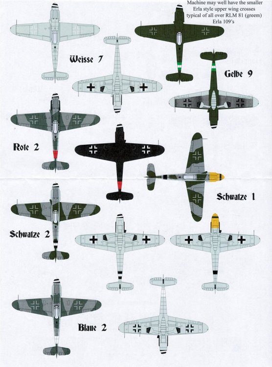
Don't have a link, but you might check out AIMS recent Late War 109's decals. They include layouts for several 109s. I don't know if they cover all of them, but should help. I will be posting a review later today or tomorrow, but here is a teaser:
 2 points
 -
 Your upper cowl for the Airfix P-51D looks amazing. Any chance of doing a main wheel well insert for that kit as well (possibly with a substantial rear wall/spar to set the proper dihedral)? Thanks! D2 points
 -
As normal I m a little bit further along than my first post, I tend to save a bit up before the initial posting. After starting on the cockpit I got distracted by the cannon inserts which I had read on another build were a bit tricky so I did that next and ended up assembling the wings, this was quite a robust bit of construction but it all went well though my first attempt with the cannon covers was a bit crooked. Next back to the cockpit Cheers Dennis2 points
-
My Hasegawa FW-190A-8 in Heinz Bar colors.2 points
-
Alley Cat Tamiya Mk viii conversion to Mk xi
Coneheadff and one other reacted to BloorwestSiR for a topic
Here's the one I built a couple years ago. On my two copies, the canopy fit wasn't the greatest but not impossible. The lower chin was also a bit short. Most people splice the front part of the lower cowl with the section of the kit part that forms the centre of the wing. The pink PR Spitfire is a bit easier. You just need to drill a hole in the side of the fuselage and paint it pink. I did that one as well but keep in mind it's a IX and not an VIII. Barracudacast make decals for this one but I used custom masks for mine. Hope that helps. Carl2 points -

Mitsubishi A6M2b Zero; 1/32 Tamiya
Uncle Toby and one other reacted to Scott Negron for a topic
Now, I don't have to make a post myself:)!!! Here is the port side Aires part. It's missing the linkage for the throttle and mixture controls, cowl flap lever and wing nut to adjust tension and threaded stock to adjust, hook to attach parachute to, and some other plumbing and controls that Ryan can probably tell us what they are (LOL)! I sure wish I could read Japanese! There's also a flexible romex cable for the cockpit light. The dyno shelf needs to be added too. Once completed I will run the cables back through the rear bulkhead, I left them extra long for that purpose. The starboard side has the added tail hook indicator and cable to the crank to retract it. The zero tail hook could be "opened up" to release the plane from the carrier arresting cable. I need to tighten some of them up. There's also a twist pair of leads to the cockpit lamp. The morse code shelf is empty. Ryan indicated probably only shotaicho or higher likely had them. I scratch build a separate more panel Here is the cockpit floor. Note the bottom of the rudder pedals. I ground the bottom out and added rod styrene to replicate the wrapped hemp pedal bottom. Later models (A6M3) had the design in the kit parts. They are also missing some rivets. I added the foot straps from wire and added the brake lines and PE brackets, and of course the rudder pedal cables. There's a spring missing as resistance for the pedal adjustment star wheel (PE part) I also re-shaped the control stick boot and added the 3 snaps. There are a few lines missing, and the T handles I replaced with styrene rod The rear panel is pretty much stock w/ PE and lead solder for the bungee cord for raising the seat: Unfortunately, my seat pictures suck:( Out of focus. I thinned it down, drilled the side lightening holes you picked out, added back the rivet details and missing brackets on the rear for the seat belt attachment. I also replaced the rear main horizontal bracket, I had to sand the original off to get the thinnest possible seat. I made the brackets seat belt retaining brackets (look like ears with 3 position holes) but don't have pics. I'm in the middle of cleaning up and painting mine so hopefully I'll have better pics soon, looks MUCH better with a coat of paint! Note the wire around the perimeter. I filled the seam w/ super thin CA glue to remove the seam, cut the corers off to replicate the outer wire frame the sheet metal was wrapped around.2 points -
LEM Mig -9 FINISHED
coogrfan and one other reacted to blackbetty for a topic
the quality is pretty good, no bubbles i see. i expect the same as with their Su-22 that i built. i always start with pinning the main assemblies: 02 by karl holubar, auf Flickr on the fuselage i used resin pourblocks cut to shape and pinned to get something to mount the wings on 03 by karl holubar, auf Flickr stay tuned...2 points -
One gear door down, one to go: A very dirty door - pretty lazy weathering. Maybe I will do a little more later. The placement of the door opening cylinder in the landing gear bay months ago was really a question mark. But I had no need to worry - it's just about right. The thin silver lip that is just above the door I added to the gear bay cutout on the fuselage. It's really supposed to look that way. That lip, or shelf, is why the hinge fittings need to be goose necks.2 points
-
BIG Stuka - Airfix 1/24 finished
BiggTim reacted to Sir Spendalot for a topic
That's freaky - they look like sketches!1 point -
Thank you, D! Yes! Wheel well bays with spar for the Airfix kit are in the design queue.1 point
-

Fokker pair
LSP_Kevin reacted to sandbagger for a topic
Hi all, Using 'Flory' fine clay wash for weathering. Just like the 'Karate Kid' - wash ON ---------- Mike1 point -

AMT 1991 Silverado 454 SS-Completed-03/21
mustang1989 reacted to Dennis7423 for a topic
That's a really great idea I never thought of! I am going to do that, too... how much did each shelf set you back? I have a modestly sized curio cabinet from American Furniture Warehouse. - Dennis S. Thornton, CO USA1 point -
Alley Cat Tamiya Mk viii conversion to Mk xi
Dainis reacted to BloorwestSiR for a topic
For the camera hole, I marked the centre of the panel with a pencil and used a small drill bit. I then used an RC car body reamer to make the hole itself. This way it's easy to get the correct finished diameter as well making sure I was still centered. I may have the Barracuda decals leftover so I'll take a look and let you know. Carl1 point -

Mitsubishi A6M2b Zero; 1/32 Tamiya
One-Oh-Four reacted to A6M for a topic
Hello Gentlemen, Scott is giving you some pretty good advice. The one item you want to add to the right side of the cockpit is the Air Fuel Mixture Analyzer Control Box. I found out I still have a Flickr account from back in 2010 and so I finally loaded two pics onto it and am going to see if I can post these images here. These illustrate the control box that was found on all A6M2s. This box was then deleted on later models of the Zero. Ryan https://www.flickr.com/photos/54116416@N02/shares/5htHU8 https://www.flickr.com/photos/54116416@N02/shares/605X4Q1 point -

GE F110 exhaust nozzle in closed position?
ziggyfoos reacted to Darren Howie for a topic
I think your best bet may be stealing a closed exhaust from a Trumpeter F-14D or B. I think most resin 110’s are all open and the only closed one in 32nd is the closed option in the Tomcat kit. im not sure if the Academy F-16 has a closed burner can someone else might chime in...1 point -
hi Alfonso glad to see your back. have you watched Kitty Hawk & Panda hobby grow? we have some exciting kits coming later Glen1 point
-

RF-8G Trumpeter & Fisher Model
HerculesPA_2 reacted to EricF for a topic
This is the idea with a quick average dry fit1 point -
RF-8G Trumpeter & Fisher Model
HerculesPA_2 reacted to EricF for a topic
Hi everyone! OMG I have a problem! I have been working on the wing with some interruptions due to my job. It' on a good way. The today update does make me optimistic and it adds suddenly quite a big additional work. Something rang a bell in my mind when I saw this. Take a look On the left, you have the Trumpeter canopy and the Fisher's one is on the right The Fisher canopy is too flat and too wide. The canopy and its fairing are exactly the same on the F-8 and RF-8 Here is the evidence here below. Sorry for the poor quality but these two pics are self explanatory. They are a shoot of my Ipad screen. They are exactly the same indeed. It seems to be logic on the manufacturer point of view to have the same canopy for costs and the management of the spare parts. Well, let us have a look on the differences between the two fuselages now The cut front part of the Trumper And the RF-8 resin part Fisher is a bit short on the front and logically too flat The both side by side now Conclusion: --> If I take the Trumpeter as a reference, that's sound quite good to me, the Fisher fuselage is too wide on the aft part of the cockpit by 2 mm and too flat by 3 mm at the canopy the fairing section. Corrective actions: --> I will cut the both fuselages along the black lines shown on pics and I will adapt the Trumpy part on the Fisher's one. I will insert next the Aires tub coming with its Avionics part as I did on the two other aircraft. It will give me the wright cockpit width. This the best solution to me to be able to display the three birds side by side without suffering of a big difference in the shapes. That's all for now. I have to put all of this into practice now. I am on vacations next week. So updates will come regularly. Cheers Eric1 point -
ok moving on next you start the cockpit section, tbh im worried about the fit to the main body, so im going to test fit every thing before i paint the tub so the wheel well has a fair amount of detail , however as mines in flight you wont see this so i decided to have a test fit and im pleasantly surprised, there looks to be a few bits to fill and sand but not much fingers crossed now while im test fitting this far, i thought id include shots that everyone is talking about now im no expert, im using the mk1 eyeball compared to photos and it does look a little flat from some angles but not that much in my opinion. However fixing it would not be as simple as some have suggested, the flattest point there i think it would need correcting, actually leads into the canopy, so you would need a new canopy as well, i cant currently take a photo with the canopy inplace as the are soaking in Klear anyway food for thought..1 point
-
1:18 Hobbyboss AV-8B Harrier
sandokan reacted to patricksparks for a topic
A little progress, Have been working on the inside frame for the canopy, what a pain, it's very complicated with plumbing, brackets boxes, bolts, shapes you name it....1 point -
According to Spitfire experten extraordinaire Edgar Brooks (RIP), the forward rake on the Spit's landing gear increased by 2" (~5cm) only from the Mk. Vc onwards, the Mk. Va/b undercarriage still had the same geometry as the earlier marks. This remained constant until the Griffon-powered 20-series when, as Dpgsbody55 pointed out, the gear legs were raked forward once again.1 point
-
Low and not slow
hamfists nz reacted to LSP_Ron for a topic
This is pretty fun Enjoy1 point -
Hi, Just for fun DFV Cosworth piston and rod. Voilà. Pascal1 point
-
6 complete submunition dispenser SUU-30 CBU-54 H/B “late” with decals & photoetched parts, post Viet War, late Cold War until 1991 Gulf War. 10,00eu1 point
-
Yes, it looks good in Italian markings. Cheers Dennis1 point
-
'perfect' !!1 point
-
 Thanks boys! To tell you the truth, my original plan was to put larger more symmetrical splotches on the fuse, and have smaller and larger more random splotches with more random shapes on the wings.......but I initially forgot about the elevators in that plan, so they ended up with the same effect as the fuselage had. Iv actually remedied that, as I think you are right, they should be alike....... I thought I'd like the larger more symmetrical splotching, but in the end I liked the more varied sized camo on the wings and elevators with the larger camo on the fuselage and vertical stab, so I fixed the elevators to match the wings. At the same time, I utilized the Maketar Do-335 mask set along with my own designs to get the white down. This includes Marseille's "200" and the crossed swords in his oak leaf & crossed swords victory crest: I'm off to let the white harden off and eat some corned beef and cabbage w/potatoes. Cheers, and happy St. Patrick's day!1 point
 -
IMHO, If you look at prices for full resin cockpits, by reputable companies, they are not cheap items. Personally, if it's well done I don't mind paying for quality.1 point
-

1/32 T-38A Thunderbird Completed
Trak-Tor reacted to themongoose for a topic
Time for the air show to start. I know many of you waited in line for some time to see it To date this is my best effort for a paint job. There's one photo over the wing where you can see the reflection of the US Air Force lettering in the wing! All the little parts came together without me dropping 1 spot of glue on the finished paint. I've only got one problem and that's the front canopy. I think it's got dust on the inside of the canopy. At some point I may have to strip it and redo it completely. I tried to future it again and that hasn't worked. 2 out of 3 aint bad. It was fine after the primer so I'm lost as to what happened but it's recoverable. The rivets and panels look crisp I think. The decals are a mix of Kitty Hawk F-5F and the Tamiya F-4 Phantom from CamPro. They all went on sweet with no silvering. The paint is wet sanded to 12000 grit with a sponge. It's all MCW lacquer paint 60/40 with MrColor Leveling Thinner. I used BMF Chrome for the pitot, wing tips, and exhaust. I sprayed some clear blue and red in the exhaust to try and get some afterburner type exhaust look for the inflight pose. Here's a few teasers as an intro to the RFI page. Many thanks to all of you who followed along and to everyone who posted suggestions, ideas, and guidance and support along the way. I've definitely made an improvement in my modeling skills throughout this whole build with everyone's help!1 point -
RF-8G Trumpeter & Fisher Model
HerculesPA_2 reacted to EricF for a topic
Some work on the right aileron With a dry fit on the wing with the flap Stay tuned Cheers Eric1 point -
Thanks so much! Here are some renderings of the 1/32 scale Beaufighter cockpit design at about 85% complete. Some of what you see will change. The cockpit parts will be 3D-printed in gray resin.1 point
-
I am 100% with you Jay - I learned a while ago that the only way to do multiples is do them at the same time and keep them in sequence with each other One of the reasons my 1/24 F7F died on the shelf was because I couldn't bring myself to repeat the whole process again to make another P&W 2800 - so there it sits with just the one.. ..now I am religiously disciplined in doing multiples simultaneously so I never repeat that mistake Peter1 point