Leaderboard

Popular Content
Showing content with the highest reputation on 01/10/2019 in all areas
-
evening ladies ..exactly why i need you on the team Jay - I saw the little blade in the intake, but had not seen it actually goes right through to the fuselage - what a wierd little structure... ..thanks for pointing it out - will be a devil to fit but will give it a go.. so I have skinned the front fairing of the intake.. first the inner liner was added and rough cut to the edge, this was later sanded & filed flush with the intake lip.. ..then the outer skin, I thought the best way was to try and wrap it as near as possible and try to get the join out of sight at the bottom... ..the skin had one good straight edge along the panel line of the first part so this was the reference point from where everything else must follow - this was taped down so as not to move in the beating process.. ..at this point the ali is coaxed to follow the compound curves with a mini ball pein hammer - this is a long process of tapping all the creases into flats... ..ultimately the metal gives way and the shape is good enough to stick down. I use contact adhesive and in this case was lucky I could unfurl the metal so as to hinge via the adhesive tape along that top panel line - that way it just folds back perfectly into position. Then more tapping and cutting and the result is a rough leading edge, but good enough to work with... ..this is then rough sanded & filed to get near to a finished surface... the photos show where I still need a few tweaks, and will try and add a sliver at the join line, but overall a tricky part is done.. ..until next time.. TTFN Peter11 points
-
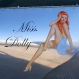
what has arrivd the last week the hawk i won with the raffle my first kit off this brand im very impresd with this small kit and when i opend the box there i found this nice touch from them Mark10 points
-
Thanks guys! That actually isnt bad news, as I changed my story to reflect Marseilles scheme change as a general tribute to JG-27s first days on the African continent. In other news on the Do-335 front, thanks to our very own Mikkel (AKA Mebo here on LSP) I now have coming to me some absolutely gorgeous 1/32nd X-4 Ruhrstahl wire guided missles to hang under the Do-335 along with the small mods (joystick and elbow rest mainly) that go with the XRuhrstahls: And the small dash mounted joystick to control them: Thanks again Mikkel!9 points
-
1:18 Hobbyboss AV-8B Harrier
Greg W and 7 others reacted to patricksparks for a topic
Moving along, I started to work on some of the aerodynamics, a little hardware on the vertical stab(alot more of that everywhere) and back on the wings for awhile, alot of scrapping needed on the leading edges, Hobbyboss made them too flat but the good thing is that they molded everything with such heavy walls you don't have to back fill it !!! Also I modified the wing root/leading edge fillet, it is far too flat on the bottom and needs to have a continuos arc from the very front back to the leading edge of the wing, easy fix, I took the kit parts that go inside the fillets and thinned the front so it would fit farther up inside the fillet and removed the internal bosses except for the very back one and removed the internal step that the peice sets on except at the back where it meets the wing's leading edge, the fillet should be full thickness and then taper towards the front in an arc. Also added the black styrene that are covers over the fillet and engine covers joints.8 points -

Wedell Williams type 45 1935 from scratch scale 1/32
Greg W and 6 others reacted to Marcin_Matejko for a topic
Hi The PZL P11 is finished, so I can do something easy and relaxing. This will be another model of a 1/32 scale racing airplane. This time, Wedell Williams type 45 from 1935, a beautiful machine with a nice aerodynamic line. The last racing plane made by Wedell Williams. More information can be found here: https://oldmachinepress.com/2015/07/30/wedell-williams-model-45/ Orginal Wedell Williams 45 ( photo from the site oldmachinepress.com) A replica of this aircraft in the Wedell-Williams Memorial Aviation & Cypress Sawmill Museum. I have some source materials that will help me during construction: I have a question, do you have any pictures of the interior of the pilot's cabin, silinics chassis and other details (can there be pictures of the replica)? I have an idea to use the elements of the Wedel Williams 44 hull from the Williams Bross (1/32) model, it is very similar . I mainly use the fuselage and maybe the engine, the wing fins and the engine cover need to be redone. in the hull also need to make many changes because in the model 45 the hull is bigger and has a slightly different shape. But quite similar, so it will be suitable for modifications. I once made a 1/32 model Laird Turner LT 14 "Meteor" with a larger model (1/30) so this time I will do with a smaller bit bigger. As for interior furnishings, it is very poor and simplified in the Williams Bross model, so it is not a good model. In addition, the hull frame in model 45 had to be significantly different because the wing structure was different and additionally had a retractable landing gear. This is how the hull construction looks like: To make the wings he used elements from a different model and plastic plates.7 points -
1:18 Hobbyboss AV-8B Harrier
Greg W and 6 others reacted to patricksparks for a topic
Felt like putting some more fasteners in today7 points -
I'm new to this forum and new to model plane building, but I thought I might share some pics of my previous project. I'm just getting ready to start a Model Airways Sopwith Camel. My intent is to replace all of the pot metal parts with scratch built pieces in brass, aluminum and copper. Wish me luck.6 points
-
ok time to try somthing not everything whent well but we have time the windows are out so i have to make new ones im not going to put much detail in the cargo bay and pit because the windows will be whaeterd so you cant look in windows in on one side so know im going to try to do a bit on the pit Mark6 points
-
Thanks for the reply's gents. Don't be confusing Machine marty's beautiful build with mine. If mine looks half as good I will be happy! I've been working in the cockpit trying to get the bombardiers station right. There is a hump where a sliding floor slides into to get to the aiming gear. I have bulkhead glued in with acrylic glue. Actually everything in this post is dry fitted with acrylic glue. I removed all the molded on details, started filling in the wing root area, added a few ribs and made a new control box on side wall. I added a cowl for the floor, after looking at pictures the front part didn't look right compared to some of the pictures I have. The structure that covers the bombing gear just didn't look right. After a bit of sawing and sanding, I'm starting to like it. Its not finished yet I still have some trimming to do to get it in the greenhouse. Plus all the detail needs to be added. Still have some adjusting to do, once I get it to fit in the greenhouse I'll start putting the detail in. All suggestions/critiques gladly accepted! Dan6 points
-
I've spent the afternoon separating the fuselage framework from their casting blocks, delicate work to avoid fracturing the brittle resin, and then working out where fits to where. These are the side structures and base ones plus the plywood cockpit floors and petrol tank: A lick of paint on the frames then the instructor's (rear) and pupil"s (for'd) throttle controls added: Whilst I'm waiting for the CA to solidly set on that lot I had a quick look at the wings and ailerons. Very precise casting meant very little clean up was necessary and the ailerons, especially the upper wing ones, fit so snugly you could almost get away with not having to glue them. More tomorrow I hope, but this really is a great little kit. The Stockholm IPMS site has been an enormous help: https://www.ipmsstockholm.org/magazine/2003/01/stuff_eng_detail_fw44.htm5 points
-

Dragon BF 110 C-7
BradG and 4 others reacted to BloorwestSiR for a topic
Thanks guys! I'm glad you are all enjoying it. I started work on the IP. The Eduard set I had used individual instrument dials rather than a complete replacement IP panel. This probably works better in the end as there's less issues colour matching the panel to the rest of the cockpit and the IP is less flat looking. I then coated the dials with some UV Gel Coat which is a thick gloss gel that hardens in UV light. This helps replicate the look of glass.5 points -
More fake wood talk.... This effect is straight sponge with no wet follow up swipe. MS Type N by The 3rd Placer, on Flickr And this is a really wet application. Metal Floor by The 3rd Placer, on Flickr And some hand painted plywood. Untitled by The 3rd Placer, on Flickr Note these are on other models and not the Baron's mount. Ryan5 points
-

1/32 Kitty Hawk F-5E Kicked Up A Notch. Oct 3/19. Finished!
A-10LOADER and 4 others reacted to chuck540z3 for a topic
Thanks again guys! Time for a timely tutorial. How to Install a Resin Cockpit Looking at my finished models, it appears that I have installed about 8 full resin cockpits, excluding added resin detail walls, etc. like Barracuda for my Mustang and Spitfire. Like most modeling skills, the first few cockpits almost killed me to install, while this F-5E one was a relative breeze in comparison. While they have all been a bit different, they all shared the following: - Excellent fine detail, but also fragile detail - Some detail that initially looks like flash, but isn’t - Lots of tiny parts, some of which never show up in the instructions - A big mother casting block on the bottom that you need to cut off and - Terrible instructions, which are sometimes illegible Tools Required: - A razor saw, with a variety of blade widths - A Dremel or similar tool with a sanding wheel - Facemask - A #11 knife The first order of business is to remove the casting block from the bottom of the main pit. Using the fuselage sides as a guide, cut off the bottom block with a razor saw so that you have at least 3/8” of clearance on the bottom. Be careful as you hold the resin to not knock off any fine detail with your hands. I usually cut down half way, then flip the pit over and cut from the other side to meet the cut half way. This clearance allows you to adjust the height of the pit within the fuselage, but also to tilt it front to back, as later required. If you’ve got lots of clearance to begin with, skip this messy and dust filled step. Tuck the pit up high on one fuselage side to see how it meshes with the kit plastic. Trim it with the #11 knife accordingly to get a snug fit. When you’re happy, attach the pit to the other fuselage side and do the same thing. Next try to put the fuselage halves together with the pit inside, with obstructions removed from the sidewalls, like anchor points for the kit cockpit. Nine times out of 10 the width of the pit will be too wide, so you need to shave off some resin from the sides with the Dremel tool. Do this where you can make a dusty mess and always wear a face mask, because that crap in your lungs may never come out again. Here’s the main strategies: 1. Take off as little as possible, which means that you should sand off the resin in thin layers, dry fit, then shave off some more. This might take 20 or more iterations, so take your time! 2. Shave off both sides equally, so that the pit isn’t off-center 3. ALWAYS get the parts to fit snugly without squeezing the fuselage together too hard. If you do, the fuselage can become swelled and other subsequent parts, like canopies and windscreens, may not fit later. While you’re doing this, shim the bottom of the pit with bits of styrene to get the pit to fit tight to the top of the fuselage halves at the same time, including the front to back tilt. You are trying to deal with 4 different things at the same time: 1. Width 2. Height 3. Forward/ Backward position, and 4 Tilt The Forward and Tilt positions may involve dry fitting the Instrument Panel (IP) at the same time, to get it in the correct position. After a lot of dry fitting, trimming and a bit of cussing, you should be ready to deal with the cockpit walls. With the pit dry-fit installed the way you want it with shims and tape, try to fit a sidewall to one side. If you’re lucky, it’s a bit too tall and if you’re super lucky, it fits right away. Using the #11 knife, carefully shave off bits of resin here and there on the sidewall to get the wall to fit snugly against the pit on the inside, rather than the outside, which causes gaps. When you’re happy, mark the exact position of the sidewall and the pit with a pencil, then move to the other side of the cockpit and do the same thing with the other wall. Next, try to dry fit almost everything at the same time, including the IP and maybe other bits that might get in the way. You will likely have to do other adjustments to get all the parts to be happy with each other. When they are, glue the sidewalls to the fuselage halves according to your pencil marks. Next, paint the sidewalls and cockpit separately, including many of the tiny parts that may be easier to paint off the cockpit assembly than on it. After you have decaled, assembled, detailed and maybe weathered your little work of art, it’s time to glue the cockpit in. This is when you need to focus on the pit to fuselage attachment more than the fuselage to fuselage join, because you can’t do both at the same time. With the cockpit dry fit in place with the fuselage halves held together with tape, using shims and tape again to get it fitting just right, ooze thick CA glue down the sides of the pit where it will bond with the fuselage plastic, using gravity to guide the flow, but not run down into any exposed areas. In most cases, the styrene shims can be glued with the rest of the plastic, assuming they won’t get in the way of other kit parts later. Hit the glue with CA accelerator, then glue another area, until you have filled much of the voids around the cockpit. Be very careful obviously, because there is no turning back. Now you can glue the fuselage halves together. Using a used #11 knife blade, spread the plastic fuselage halves apart and ooze Tamiya Extra Thin cement in the gap, then let the mating surfaces fuse together as you move the blade along the seam, repeating this process in a zipper-like fashion until all seams have been glued together. After that, you guys know all the rest! Here's my last Black Box pit, fit and glued into my F-15C Eagle Good luck and if you have any questions, fire away. Cheers, Chuck5 points -
Here is one from the Korean war, at the left side: Jari5 points
-

New to Airplane Models...
Anthony in NZ and 4 others reacted to Garage21 for a topic
Actually Rigor - No - I'm an accountant. I taught myself machining. Which means I have an idiot for a teacher. My "shop" if you can call it that is actually three 5' x 8' closets in my garage that I've turned into a cut shop, workshop and machine shop. Even my shops are scale miniatures, but I can fabricate just about anything that you might find in a full-scale machine shop. Well... Let me rephrase that... I have the TOOLS necessary to fabricate anything from a full-scale machine shop. My skills are sorely lacking, but I figure things out as I go as best I can given my bad eyes and arthritis.5 points -
evening folks & thanks for stopping by Yep, thanks Jay, I spotted that on the drawing, it was just easier to start with a rough shape and get rid of the form to capture the intake - please keep your notes coming though as I easily miss things! I think it might be - it's certainly directing airflow somewhere:) so, more mustang mayhem... ..after shaping the basic filler construction of the airscoop, next was cutting out the air intake on the roof - I made a template from the drawing.. ..then with filler & dremal work I got the rounded sections done.. ..after this I had toreskin the inside as the skins I put in earlier had a join line down the middle and the real one doesn't. To dothis I lined the interior with tape and drew out the boundaries to when I remove the tape I can unravel it and get a template for one piece of rivetted litho to dress the inside in one go.. ..next I wanted to get the positioning right so I can partly skin the scoop in aluminium and fit it so I can add all the fuselage skinning later on.. This took the entire morning to get right as it is such a critical feature of the airframe (not helped by the plans I was using having it in the wrong position too far back...) I put tape on the mating faces and added tiny drops of CA to hold it in position so I could add the filler - this process was then reversed to I make the part match the fuselage - the net result is the parts fit together seamlessly... ..it was also braced inside before I started so the filler didn't collapse under load... ..then the fist bit of ali skinning on this model - coincidentally the first on my Spitfire was also an air intake.. ..hard to see whats going on here, but on the right hand side is a sheet of soft ali under some masking tape - it is being held, rubbed,, stroked and tapped with a tiny hammer to start to conform to the shape of the roof. the black tape borders can also be seen at the nose - these leave an imprint in the ali so I know where the borders are. Its a tricky shape as not only the shape of the scoop, but also the flaring at the top where it fairs into the fuselage... ..I end up with a useable part that has adopted the shaping well.. this was added with contact adhesive... ..then the other side - this time with the added complication of the intake aperture.. ..it proved impossible to do the little intake in one piece so I added another in the inlet,,, then after cementing all the tape is removed and we have the base layer of ali down... you can see it's quite rough and creased in places, but this all sands out... after sanding aout all the defects the first sking is done & just needs finessing & rivet details but I will leave that until later ..the intentionj is to get all i can done while I have access (so a bit of the wing surface where this sits needs to be done too) and then fix the scoop in place,, the nose intake is next and that is going to be a real challenge TTFN Peter5 points
-
Hi Folks, It’s a New Year and I am planning to start my 1/32 Intruder. Decided to get cracking as it will be entered into 2 local g/b - one on Vietnam and the other on carrier crafts. Been ages since I entered a local group build, so I’ll try my best to enter both and kill two birds with one stone the kit will be mainly OOB and thanks to Mark on this forum, I have nice decals to use on the kit. Not going to correct the seats....might just put two crew figures in there..... pics of box and decals. Hope to start by next week hope all goes well....got a new PS4 for Xmas.....eating into Modelling time....I must admit best regards and happy modelling in 2019....to all brian4 points
-

1/32 Italeri Cf 104
R Palimaka and 3 others reacted to MikeA for a topic
After over two years, this one is finally done! The kit does build into an impressive model pretty much out of the box, if the fuselage panel lines are sharpened up a tad. I chose a longer route and foiled the beast, after an overall sand and polish, to deal with those pesky panel lines. There is a fair amount of scratch building in the cockpit, using the kit pieces with any semblance of detail removed as a basis, and also some of the Eduard panels. Many of the Eduard pieces were chopped and rearranged to get what I wanted. The flying instrument panel and instrument shroud/gunsight were scratch built as neither the kit nor the Eduard parts present the Canadian version. The build can be found here. Overall, no problems. Glue the front and rear fuselage sections together before joining the fuselage halves and use internal fillets for the wing/fuselage joints are the only essential tricks on this one. Extras used were: Eduard interior Airscale instruments and bezels Aires control columns Eduard electronic boxes (chopped up and added to) Eduard exterior (only a couple of pieces in the end - I should have saved my money and used whiskey bottle foil instead) Eduard seat with fabric belts(very very nice - essential really) Eduard wheels (the kit ones are incorrect for the Cf 104) Eduard burner can Aires wheel bays (the main bay is especially good and for the most part is visible despite the gear doors) Master pitot tube (metal and essential for durability alone) Videoaviation wing and central pylons (also beautiful pieces) CMK rocket pod (chopped and modified - I only needed it for the end pieces which I had trouble scratch building) Canuck Symmetrical Markings (amongst the best decals I've come across) Wessex Transfers (to print the decals for the Aete "X" markings and the tail flash) Mike Grant decals (various placards and a couple of instruments) It was my first attempt at foiling and I am extremely grateful to members of this forum for their helpful posts on achieving that. It was suprisingly relaxing and certainly way more spouse-friendly than Alcad. For the record, I went through just over 400 cotton buds, 500ml of alcohol, over 40 blades, and somewhere around a metre of foil to do the job. The foil was common kitchen foil with heavy duty foil only used when I was treating it with bleach and egg shells. The Microscale foil glue was cut 50/50 with alcohol and sprayed onto the foil in two misted coats. And the airbrush survived without coming to a sticky end. I used a limited amount of chrome Bare Metal Foil for the canopy framing and the leading edge of the vertical stab. No polish was used as i wanted to retain the natural variation in the panels. Hard to photograph as it is quite subtle across the bulk of the fuselage. There's only very light weathering using oils and Flory washes. It was also my first foray into attempting my own decals. The artwork was easy using a free download of Illustrator, but the successful printing on our Canon inkjet was not something I was able to conquer. I managed to get them printed and coated without colour bleeding, but the final product was just too flimsy and transparent to work with. The first couple of photos were taken outside, but the sun is a tad harsh. The model is surprisingly long and a beggar to photograph. Many thanks for the encouragement along the way! Any comments, suggestions etc on the finished model are welcome. I'm certainly happy with it overall - I've almost forgotten the couple of errors already! Hope you like it. Cheers, Mike4 points -

MIG-15 Bis BG Air Force Trumpeter 1/32
BiggTim and 3 others reacted to ShelbyGT500 for a topic
Hi friends small update, but a lot of work - remove the engine-oil covers and start to detailing the air-brakes bays with etched parts: Cheers guys4 points -
The wood grain was great fun but took a few tries to get it right. Most of us know the light brown color is applied and then oil paint is streaked across to replicate grain. Sponge applicator by The 3rd Placer, on Flickr After a few failed attempts I discovered that if you applied the oil paint "dry" and then followed up with a moist brush you could get some neat effect such as seen on the floor board, gauge panel, and engine bearers. Red Baron by The 3rd Placer, on Flickr Red Baron by The 3rd Placer, on Flickr The large mineral streak in this pic was achieved by this technique applied to only half of the upper panel resulting in the dark line you see...very effective. Red Baron by The 3rd Placer, on Flickr Ryan4 points
-

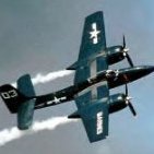
Corsair, can it have one wing up and the down?
D.B. Andrus and 3 others reacted to MikeMaben for a topic
2 short videos ... Both wings simultaneous... https://www.youtube.com/watch?v=FQxb-V-rZqA&ytbChannel=null One wing at a time ... https://www.youtube.com/watch?v=-vvbF7IumME4 points -
Now that the majority of the major work has been completed it was time to start to focus on some of the smaller details. Close examination of photos reveal details that by themselves are no big deal but combined will certainly add a lot of realism to the model. Not sure what role it performs, but there is a small round circle under the cockpit represented with an engraved line on the kit. Most pics show this to be inset and not flush with the fuselage skin. I drilled it out and installed a flat disk punched from plastic card. The next detail that I wanted to add was the small fold out step used to gain access to the cockpit. Like most tail draggers, entry is by climbing up over the wing and this step is right where it’s needed. Represented on the kit by a nicely engraved panel. I chiseled out the hole required I made the step by filing down some brass plate and added the outer cover from thin aluminium window blind shaped to exactly fit the previously chiseled out hole. Dry fitted A small but important detail that will bring the model to life.4 points
-
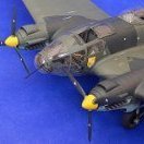
Final pics for this build. Here is the complete Dragon model in a small diorama. It depicts a break for the ground crew about to affect an engine change after some rainfall.4 points
-
For a while I was on a Ferrari Formula 1 kick. I built the 126 C2 and 643. LOVE building Ferrari engines.3 points
-
this is my entry for the group build I whant to do it longer to build a diorama so now it will be a good time to go for it the idee came when i whas surfing the net for info when i found this pic so i wil try to make this what i have so far this wiil be long term but we have a year i can work on the armour for distraction because there is a lot to do to convert the mi-17 most importend thing just having fun Mark3 points
-

P-51K Nooky Booky IV
Rocat and 2 others reacted to Miloslav1956 for a topic
P-51K Maj. Leonard "Kit" Carson 1/32 Tamiya HGW wet transfers & belts Barracuda wheels Colors MRP, Gunze Sangyo, Alclad3 points -

OV 10D - BRONCO
BradG and 2 others reacted to Squito2340 for a topic
A bit of deliberation and hopefully will build more that one kit during this group build but, going to do a Bronco whilst I wait for a few bits for the Lancaster. A few scratch built items should find their way into this model. Lots of visible stuff in the cockpit area...model not started as yet. Photos to come.3 points -
MiG-17 VS F-4
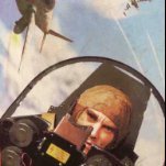
Cheetah11 and 2 others reacted to Alain Gadbois for a topic
Hi all! Found this and I think this is incredible historical footage of the start of the Yom Kippour war of 1973. It starts like any ordinary vacation footage at the beach somewhere in Israel until MiGs fly over...Don't mind the poor film quality in places. And for those of you not interested in this subject, there's a Swedish girl in a bikini at the very end (its true!). Bye for now, Alain3 points -
Jumpei Temma drawings & article on Ki-43 Hayabusa Oscar
LSP_Kevin and 2 others reacted to Alain Gadbois for a topic
The Revell kit is typical of their kits of the era: raised panel lines and little interior. But the raised detail is quite fine and shapes appear OK. I would do a camouflaged one. The interior is the most disappointing, but is there aftermarket for the Hasegawa that could be used? Alain Didn't notice all that dust when taking the photos, sorry!3 points -
Got some work done on these two...cast some parts,detailed as well...will have a lot of clean up and smoothing out surfaces to do as well...so pitter patter. camera ports and cameras next. Did pick up a great book...has already proved invaluable. Cheers fer now3 points
-
1/18 P51C Mustang "Lopes Hope the 3rd"
daHeld and 2 others reacted to R Palimaka for a topic
Incredible work as usual. A hammer...I've often thought of using one on my models, but not to build anything... Richard3 points -

Revell super Hornet
Ryan and 2 others reacted to scvrobeson for a topic
Still like that we're getting a 1/32 twin engine jet for less than $100. Pretty rare these days. Matt3 points -
HK Model B-25J Backdated to a B-25C/D, Fingers Crossed
patricksparks and 2 others reacted to Out2gtcha for a topic
I know you are currently working on other stuff Patrick, but were all hoping this one isn't on the SOD for good! Its too good to put out of our brains for long...............3 points -

Me 110 dayfighter : Winter camouflage, Russian front: FINISHED
BloorwestSiR and 2 others reacted to Erwin for a topic
Anno October 1943. Luftwaffe directive nr 256: All aircraft on the Eastern front must be painted overall white,by whatever sort of paint and tools available. The balkenkreuzen,swastika's and yellow identifications are to be left unpainted. (translated from German)3 points -
MiG-17 vs MiG-15
mpk and 2 others reacted to Alain Gadbois for a topic
The MiG-17 is a different kit, but it has parts from the other kit in it. The engine is the same as the MiG-15 kit so the fuselage cut is in the wrong place (20mm too far back). It is very clunky, the wing tips are way too thick, the clear parts are inaccurate, etc... It looks like a MiG-17 from a distance, and appears better as you step further away! Alain3 points -
A little more progress to report... Guns painted and fitted to wing. I painted the guns satin black and then gave them a wash with highly thinned flat aluminium. They look better in the flesh than they do in the photos. The finished wing. The metallic colours catch the light badly in the photo. I painted the gun belts with bright brass and then gave them a treatment of black wash to bring out some of the fine detail. not sure what else to do in there... I'm only leaving this side open and have glued in the covers on the other completed wing. I'm having photobucket issues, so couldn't get any more photos to upload. Is there any other way of adding pictures to a post instead of using the torturous photobucket? Thanks for looking!3 points
-
Corsair, can it have one wing up and the down?
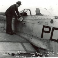
Vandy 1 VX 4 and 2 others reacted to LSP_Ron for a topic
Its these pictures that I am looking for3 points -

Revell super Hornet
Shawn M and 2 others reacted to alaninaustria for a topic
Am I seeing this correctly? On page 14/64 it says to shave off 0.5mm and cutout 2mm in a slot? What the h*** did Revell do all these months? Last I remember, we were supossed to be getting a super kit where both the E and the F version were build options? The flash removal is acceptable, but shaving parts to fit? I have to give them credit for being honest... but, seriously? What gives?? Cheers Alan3 points -
3 points
-
Short Sunderland MkII
daveculp and 2 others reacted to tomprobert for a topic
Afternoon all Some more progress on the Sunderland to update you on... One of the main problems when building big vacs like this the fact that due to the nature of the plastic and the fact there's no interior provided, the fuselage lacks structural integrity - especially when it comes to adding the wings and tail, etc. Therefore, lots of internal reinforcement is needed to provide enough strength for the model to be able to support itself. So it was out with the profile gauge and thick plastic card, and slowly bulkheads began to emerge... DSC_0039 by Thomas Probert, on Flickr For anyone familiar with the internal layout of the Sunderland, you will quickly see these bulkheads and floors are far from resembling reality, but considering next to nothing of the interior will be visible I went for strength over accuracy. The centre-section 'bomb room' as well as the nose section and cockpit are more in keeping with the real thing, however: DSC_0035 by Thomas Probert, on Flickr The other fuselage half... DSC_0037 by Thomas Probert, on Flickr ..now slides nicely over the other... DSC_0041 by Thomas Probert, on Flickr ...apart from the fact that the starboard fuselage is approx. 4-5mm deeper than the port - a bridge I'll have to cross at a later date! The sheer bulk of the fuselage and the size of the real aircraft is quickly becoming apparent: DSC_0043 by Thomas Probert, on Flickr A few more bulkheads to fabricate, and then it'll be on with making the finer details of the interior areas that will be visible. Until next time, Tom3 points -
1/32 Kitty Hawk F-5E Kicked Up A Notch. Oct 3/19. Finished!
Derek B and 2 others reacted to chuck540z3 for a topic
The instrument panel, attached to the glare shield, is really good too and no doubt derived from the Hasegawa IP on the left. The Kitty Hawk IP on the right? Meh… The instructions don’t tell you what the heck to do with it and the kit even supplies a big IP decal. I have no idea what you’d do with it, because it will never fit this piece of raised plastic. Experts will note that the IP’s do not have the later RWR radar warning instrumentation. I don’t care. But would the Black Box resin cockpit fit the Kitty Hawk kit?? Eyeballing it for several hours, I decided that it had a very good chance. I have a Love-Hate relationship with resin cockpits and here’s the thing I hate the most. You are better to cut off a bit too much and shim it later than leave it too deep, which could stress the plastic. Next, you need to cut off the tabs on the side of the fuselage, which are amongst a moonscape of pin marks. Good thing they will all be covered later! After cutting off these parts including the rod antenna that isn’t needed and after LOTS of dry fitting and trimming, the side walls were glued into place. The fit isn’t perfect for obvious reasons and while the scalloped tabs on the top of the sill are on the resin parts, they don’t sit high enough to see them from the outside. The fix, which also covers the sidewall join is to use the kit PE brass, trimmed to fit some of the resin detail. Again, after lots of sanding and dry fitting, the cockpit slips into place as a dry fit. Note that the joins with the sidewalls will tighten up when glued permanently. Those fuse box thingies on the shelf behind the seat are just placed there to see if they cover any gaps on the sides. They do. The rear fit is pretty darn good considering this cockpit is made for the Hasegawa kit and I did not need to trim any of the top. With the front IP and glareshield dry fit, I wanted to see what the windscreen will cover. Compared to pics of the real deal, the fit is fantastic. Again, note that everything is just dry fit with plastic shims in place. Note the detail within the canopy hook slots, provided by the resin sidewalls. So there you have it. The Black Box F-5E resin cockpit not only fits the Kitty Hawk kit, but the detail is superb and the instrument panel blows the kit one away. Next up, I will try to fix some of the panels on the sides before I paint the fuselage walls. The lack of an AOA vane on the starboard side, which would fit into the wrong square panel rather than an oval one at the top, is first on the list. Thankfully, the Hasegawa kit has an AOA replacement! Cheers, Chuck3 points -

1/32 Gotha G.I Scratch Build
Starfighter and 2 others reacted to guitarlute101 for a topic
Thanks for the kind words guys, I appreciate it. I had time today to take out the scroll saw and work on the bottom of the front fuselage. Draw it and saw it. Sand sides nice and even...………….. This is just the buck to form the plastic around so it has to be .030 smaller so that the plastic card on the outside of the buck will be the same width as the rear fuselage. My plan is to make the bottom of the fuselage out of 3 pieces of plastic card, the bottom and two sides. I've never tried it this way before so we'll see. The difficult area will be the front of the fuselage. If all else fails then I'll vacuform it. Here you can gauge the size that it will be in it's final form. That's it for now, little by little. Thanks for looking in. Mark3 points -
1:18 Hobbyboss AV-8B Harrier
Greg W and 2 others reacted to patricksparks for a topic
Finally figured out the mystery instrument panel shroud, countless hours of photo interpertation....no kits have anything close to this thing... the new one is in the foreground the kit part that I tried to modify is at the rear. I still have to put the defogger tubes on the sides of it. \3 points -
HK Model B-25J Backdated to a B-25C/D, Fingers Crossed
Martinnfb and 2 others reacted to patricksparks for a topic
Progress is slow but getting a few things done...G Factor landing gear, Co-Pilots seat and short back armor in, needs seat belts, a little wiring and plumbing in the Navigators compartment and the wings and nacelles getting ready for paint and some chipping.3 points -
It looks as though the long awaited Revell Super Hornet is finally breaking cover - Feb they're saying I know we're heard that before , but to prove it this time we've got the instruction sheet Instruction sheet The only issue I have is that the main u/C legs are multi part , and will need replacing with something more substantial , but other than that , to my inexpert eye , it looks a better option than the Trumpter model... Have it ! colinR2 points
-

A-6 A Intruder VF-75 "Sunday Punchers"
ShelbyGT500 and one other reacted to Chris1811 for a topic
Hey guys Now comes another chunk I built three years ago. This is the trumpeter a-6 Intruder. I built an A-6 A of the VA-75 "Sunday Punchers ". I have used the following accessories. Avionix Resin Cockpit BLC32061 Retro Wings RW32002 GRU-5 ejection seat Eduard 32813 A-6 a interior set Profimodeller 32189 Interior Set Profimodeller 32188 Exterior, Ladder set Zotz ZTZ 32/061 Intruder Vietnam War decals Here are some pictures during the construction. The excellent resin cockpit I have made some remodeling work in order to present an a version. I think the pictures speak for themselves. I think I've done everything to build an a version. At this point I would also like to thank Lothar for his support. And now it goes on with..............2 points -
Hasegawa Ju87G Kanonenvogel - vacuforming done!!
Martinnfb and one other reacted to D.B. Andrus for a topic
Sure can't tell you have trouble with small PE....looks perfect! Cheers, D.B.2 points -

Resin Merlin or Packard Merlin Engine??
Rick Griewski and one other reacted to Harold for a topic
This has absolutely no relevance to your question, but I see "Packard" and my brain goes back to another lifetime, another war. I was an engineman in the US Navy, my first boat had 4 Packard V-12's for main propulsion...nothing to do with the aviation engines, just flashing back...LOL2 points -

Marine F-4J Phantom - Decal time!
Greg W and one other reacted to Durangokid for a topic
Finished the IP and attached the HUD glass. I think the superglue worked out a bit better than the clear part. Unfortunately, the film behind the panel fell off and I had to re-glue it back on but I didn't get it lined up right. I didn't notice this until after everything was glued together.2 points -
Here you go... Great choice, if I still owned a 111 I'd be entering with it!2 points