
STM
-
Posts
192 -
Joined
-
Last visited
Recent Profile Visitors
1,526 profile views


-
 Seversky reacted to a post in a topic:
Airfix 1/24 F6F-5 Hellcat
Seversky reacted to a post in a topic:
Airfix 1/24 F6F-5 Hellcat
-
Seversky reacted to a post in a topic:
Airfix 1/24 F6F-5 Hellcat
-
Seversky reacted to a post in a topic:
Airfix 1/24 F6F-5 Hellcat
-
Seversky reacted to a post in a topic:
Airfix 1/24 F6F-5 Hellcat
-
rafju reacted to a post in a topic:
I got a package from the Czech Republic today.....
-
Since there is a steel rod through both the gear and the fork it may not be necessary. I will just see and adjust fire as necessary
-
Out2gtcha reacted to a post in a topic:
G-Factor F7F Tigercat Landing Gear (HPH kit)
-
The castings look pretty rough and will take a fair amount of clean up. Close inspection of the gear struts in my kit reveals that there is a steel rod skeleton imbedded in all of the resin strut pieces! That is an awesome touch. I was afraid that I was going to have to do that myself; make the skeleton from steel wire, drill a channel in each strut, insert the skeleton and fill the channel and wire with some liquid resin. HPH did it for me.
-
MikeMaben reacted to a post in a topic:
I got a package from the Czech Republic today.....
-
scvrobeson reacted to a post in a topic:
I got a package from the Czech Republic today.....
-
Out2gtcha reacted to a post in a topic:
I got a package from the Czech Republic today.....
-
Trak-Tor reacted to a post in a topic:
I got a package from the Czech Republic today.....
-
I like a challenge! I, like you, was delighted to find a "braille scale" Tigercat. I have examples of all the other Grumman piston powered "cats" and this one will complete them. I have the 1/32 Hasegawa Hellcat where I completely tossed everything except the exterior pieces and scratch built the cockpit, firewall and everything forward of it (except a metor resin R-2800), wheel wells and landing gear, port .50's, everything aft of the pilot's bulkhead, dropped the flaps and separated all of the flight control surfaces. Right now I am working on the 1/24 Airfix F6f-5 and although it is an excellent kit, I am doing a fair amount of scratch building on it too. I have an online build page on my website: Airfix 1/24 F6F Hellcat | scottmurphyphoto (scottmurphyphotography.org)
-
STM reacted to a post in a topic:
I got a package from the Czech Republic today.....
-
STM reacted to a post in a topic:
I got a package from the Czech Republic today.....
-
Boy oh boy!. I have looked over many of the pieces, the level of detail is astounding. I doubt there is much I will have to add to this one. This is, however, my first all-resin kit so it should be a learning experience to say the least.
- 14 replies
-
- 10
-
-
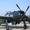
I have not spent much time looking at this kit but the first thing that sticks out to me is that the spinner shape is wrong. The kit spinner looks too elongated and blunt compared to reference photos. Depending on how thick the styrene is you may be able to correct this.
-
STM reacted to a post in a topic:
Airfix 1/24 F6F-5 Hellcat
-
I built this kit about a year ago. The cockpit was pretty spartan and the consoles (a pet peeve of mine) fictional. I downloaded the Bearcat pilot's manual and rebuilt the consoles. The wheel wells were usable but there was an awful gap between the center section and wheel wells themselves. I ground all the trunks smooth and made new ones out of Milliput. I did scratch build everything from the pilot bulkhead aft and left the large fuselage entry panel open. The engine was acceptable but required a fair amount of work to bring it up to my minimum standard. Overall this is a good kit of an oft neglected subject.
-
No, they were just friction fit for the photograph.
-
I spent the better part of a day doing the exhaust stubs. They are very convoluted and each piece had two parts. The first two were an exercise in frustration but once I got into a rhythm, they went pretty smoothly. It was here that the very tight tolerances in this kit became the most apparent. It took some fiddling to get the stubs past push rods, heat shields and spark plug wires until they fit into their respective holes. I really did not have to do much here, I drilled out the exhaust stub ends to a more scale thickness and filled seams in the pieces. I painted them Testors Metalizer "Burnt Iron" and then weathered them with pastels. All of the supercharger bits are together and painted, I just have to connect everything up. The large oil tank that attaches to the bulkhead is well detailed, but strangely enough, has no oil line piping. Not to worry, a little bit of solder will fix that.
- 67 replies
-
- 12
-
-

-
The engine is now completely finished and better photographed. I gave the entire engine a coat of clear semi gloss once everything is in place. Radial engines were notorious "leakers" so I dirtied it up with some Tamiya black and brown panel line detailer and AK Interactive "Engine Oil". The AK stuff is fantastic. Airfix did a very good job on the engine but I took it a step further. This piece took some fitting as the parts had a very tight fit. I now have to get started on everything from the firewall forward.
- 67 replies
-
- 18
-
-
-
STM reacted to a post in a topic:
Airfix 1/24 F6F-5 Hellcat
-
After over a week and a half the engine is for the most part complete. I have to add the air intake ducting to the back of the engine tomorrow. At 1/24 scale you can see how large this engine is!
-
 STM reacted to a post in a topic:
Airfix 1/24 F6F-5 Hellcat
STM reacted to a post in a topic:
Airfix 1/24 F6F-5 Hellcat
-
no worries!
-
The other component of the propeller governor is now complete. There is not much work needed on the magnetos so after that next up is the carburetor.
-
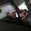
What sidewall are you referring to? If you are talking about the right cockpit side, that is not black, just in shadow.
-
STM reacted to a post in a topic:
Airfix 1/24 F6F-5 Hellcat
-
With the collars complete, I moved onto the engine itself. The propeller governor was pretty basic. The two areas of the model which are the areas of greatest interest are the cockpit and engine, especially if it is a radial engine. I started with the front of the engine and will work backwards. The propeller governor is pretty basic. I found an excellent photo of one so it formed the basis of the work. This was 6 hours worth of scratchbuilding. The cooling fins are pieces of 0.005" styrene sheet. The propeller shaft was solid, though it should be hollow and the splines to hold the propeller were flush with the sides of the shaft, which of course would do no good. I drilled out the center of the shaft, drilled 8 holes around the top and added a piece of 0.010" x 0.020" styrene strip to build up the splines. There is a hexagonal nut at the center of the spinner so I drilled out the rod in the center and replaced it with a piece of 0.040" styrene hex rod. I also added 0.010" rod to simulate the "bolts" to the nuts that are holding the spinner halves together.
-
Work on the engine has begun in earnest. The first thing I did was make some attachment collars to go around each cylinder. In this large a scale, their absence is noticeable. I made a couple of careful measurements and with a little trigonometry (I hate math but I have to admit that sometimes it comes in handy) made some circles out of 0.010 styrene sheet. I then used my "The Chopper", one of the handiest of all modeling tools I have ever come across, to cut off 0.015" thick sections of 0.030 styrene hex rod to make the nuts. The actual collars had around 20 nuts per collar but there is no point in losing my mind over that. Even at 12 per collar, that would be over 200 of them for all 18 cylinders. So I made 5 collars and attached them to some 0.040" styrene sheet and will cast them. Once cast I will remove them from the block with a large X-Acto chisel, make a cut in them to for a "split ring" and slip them around the base of each cylinder.